

Last Updated: 09/13/2020 @ 04:58 am
This content was submitted by supporters (social media and/or online forums) to help inform and educate others. If you would like to request removal click here. For additional info, please visit our Legal Terms & Conditions.
Member Credit: ajm8127
I did a 5 speed swap two weeks or so ago and there was a lot of time spent wading through the FSM pages to make sure the electrical system of the automatic chassis was compatible with the manual transmission, and the functionality of a manual chassis. This is a guide I came up with the try to easy the confusion when swapping a automatic transmission out for a manual one. I followed the procedure outlined below and used a 1997 manual ECU in my 1997 automatic chassis and can happily report that I have no CEL.
I. Introduction
This is a guide to those of you who wish to swap the automatic transmissions out of your fourth generation Nissan Maximas. It will walk you through the procedure to convert the electrical system. There are four areas that must be addressed in order for your car to be as close to stock as possible, electrically and functionally speaking, after the swap:
Reverse Lights
ASCD Cancel Switches
Clutch Interlock Switch
Park/Neutral Switch
As always, when working on the electrical system of your car, disconnect the battery.
II. Reverse Lights
Relevant FSM section:
EL – Exterior Lamp – Backup Lamp
In order to pass safety inspection in many states, the reverse lights must come on when the vehicle is placed in reverse. On the automatic this is achieved thought the inhibitor switch which is mounted to the front of the automatic transmission. On the manual version of the car, the reverse/neutral (R/N) switch handles this. When reverse is selected, the switch completes the circuit and sends battery voltage to the reverse lights.
I used the R/N switch harness from the manual version of the car, and soldered it in place where the inhibitor harness used to be. You will notice on the R/N harness you have two think wires and two thin wires. You will need to connect the thick wires in this step. First thing is first, cut off the two connectors that plugged into the inhibitor switch when the automatic was in the car. Next, locate the green and green/white wires on the inhibitor harness. The green wire supplies battery voltage, and the green/white wire runs back to the reverse lamps. Luckily for you, the wire colors on the R/N switch harness are the same. Using the thick green and thick green/white wires on the R/N harness, connect them to the green and green/white wires on the inhibitor harness (Figure 1). I have used shrink wrap tubing to insulate the joints, but electrical tape will work as well.
III. Clutch Interlock Switch
Relevant FSM section:
EL – Start
AT – Wiring Diagram
In order to prevent you from starting the car in gear, the vehicle is equipped with a circuit that will only energize the starter solenoid if it detects you are in neutral or park. Again, with the automatic, this is accomplished based on which contacts of the inhibitor switch are connected. On the manual, this is accomplished by sensing when the clutch pedal is fully depressed. To keep this functionality after the 5 speed swap, you must connect a wire in the inhibitor harness to the clutch interlock switch (switch that senses when the clutch is fully depressed). The other side of this switch must be tied to ground, so that when the clutch is fully depressed, the wire on the inhibitor harness is grounded. Fortunately, when you do a 5 speed swap, you will have a bunch of wires left over that are unused. This will allow you to easily run a wire to from the engine bay to the cabin by using some of those unused wires. For this task, I have used a yellow/blue wire to complete the circuit to the clutch interlock switch (Figure 1.) This yellow/blue wire used to tell the TCM (Transmission Control Module) when the vehicle was in drive. Connect the green/orange wire from the two conductor side of the inhibitor harness to the yellow/blue wire, on the seven conductor side of the harness.
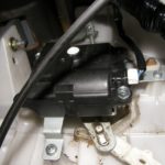
The next step is finding where this wire comes out in the cabin. The TCM is underneath the BCM, directly in front of the shifter. Its harness looks similar to the ECU harness in that it has a 10mm bolt securing it. Find the yellow/blue wire and cut it from that harness (Figure 2). It will be in position 18. Also, find one of the black ground wires, and cut it as well. This will be the ground that one side of the clutch interlock switch is connected to. The grounds are positions 15 and 48. Next, you will need the clutch interlock switch from where ever you got the clutch pedal. It will be in a harness with the ASCD brake and clutch cancel switches, along with the brake light switch. Remove the clutch interlock switch connector from this harness and extend the wires on it (Figure 3). Add enough so that they reach the TCM connector with about six inches to spare. At this point I wrapped electrical tape around these wires to keep the harness looking stock. It also keeps the wires in a bundle, which makes them easier to keep out of the way. Route these wires under the dash and around into the center console. Now connect one of the wires from the clutch interlock switch to the yellow/blue wire from the TCM harness. Connect the other wire from the switch to the black ground wire on the TCM harness (Figure 2).
IV. Park Neutral Switch
Relevant FSM section:
EC – Park Neutral Position Switch
AT – Wiring Diagram
Nissan engineered the electrical system in the fourth generation Maxima to be able to sense when the car is in park or neutral. If you have been paying attention up to this point you would have probably guessed that in the automatic, this is done by the inhibitor switch in the P or N position. Of course, we removed the inhibitor switch. To take its place in the manual, the reverse/neutral switch is used. Look back under the hood and find the additional two wires coming from the manual R/N switch harness. They will both be thinner than the two connected for the reverse lamps, and will be green/white and black in color. Now, locate the two wires coming out of the inhibitor harness that are pink/black and purple/white. I connected the wires with the white tracer together (purple/white to green/white) and I connected the pink/black to black (Figure 1). Again, find the TCM harness and connector, and cut off the pink/black (position 17) and purple/white (position 16) wires. Also, cut off the other ground that you did not use in step III (position 15 or 48). Additionally, you need the wire that runs to ECU pin 22 form the TCM connector. This wire is green/orange, and is in position 13. You now need to connect the wires from the R/N switch to ground on one side, and the ECU on the other. Connect the pink/black wire to the ground wire from the TCM connector, and connect the purple/white wire to the green/orange wire that runs to the ECU (Figure 2). Now, when the transmission is in neutral, ECU pin 22 will be grounded.
V. ASCD Cancel Switches
Relevant FSM section:
EL – Automatic Speed Control Device
Automatic Speed Control Device is a fancy phrase for “cruise control”. In order for this system to function properly, it must disengage when the clutch is pressed or the brake is applied. Of course in a car that used to be an automatic, there is no clutch, so only the brake pedal has a switch. Because you will be adding a clutch pedal, you will need to sense that as well if you wish for the system to function properly. You will need the ASCD pedal switch harness from a manual car. This harness is easily identified as the one that plugs into the pedal switches. You should have already used a portion of it in the Step III when you hooked up the clutch interlock. You can remove the brake light switch connector from the harness, as that is not used (it is the larger one). Now, unplug the ASCD brake cancel switch from its connector, and remove that connector from the car. Connect the wires running to the ASCD brake/clutch cancel switch harness to the wires that used to connect to the ASCD brake cancel switch. Effectively what you are doing is wiring these switches so that if either the brake of clutch pedal are pressed at all, the ASCD system will turn off the cruise control until you reset it (Figures 4 and 5).
VI. Conclusion
If you have followed the directions outlined above, you should have successfully completed the electrical portion of the 5 speed swap enabling you to have all the functionality of the 5 speed car in your automatic chassis. If you have also received a manual ECU from a car compatible with your model year’s emissions, you should be able to complete your swap CEL free.
Figure 1. Inhibitor and R/N switch harness
 Figure 2. TCM harness and connections.
 Figure 3. Extend the wires on the clutch interlock switch harness to reach the TCM connector.
 Figure 4. ASCD brake pedal cancel switch disconnected and wires from the ASCD brake/clutch pedal cancel switch harness.

Figure 5. ASCD brake/clutch cancel switch harness wired to ASCD brake cancel switch harness.
 Figure 6. Manual R/N switch harness and automatic inhibitor harness become one.

![]()
Comments are closed.