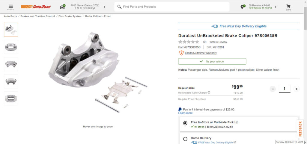
If you are looking to upgrade your Maxima with Akebono’s then check out the deal below at Autozone. You can get both calipers for $200.00 bucks. You can exchange your previous calipers to save the core charge. These calipers work great and are just like the original OEM ones.
Front Driver Side Part Number: 97S00635A Front Passenger Side Part Number: 97S00635AB
Depending on the Maxima year, you will also need the following:
This is just a quick guide for those upgrading to R35 GTR injectors. They are many fakes out there in the market. While some have had success with the fakes, the majority have experienced issues. These injectors are most commonly used for running E85 on Nissan Maxima builds.
Your best chance is to buy them used from someone who can verify they are genuine. However, if you ever plan to boost the car, it doesn’t make sense to buy the GTR injectors new because for about the same price you can get a set of new Injector Dynamics injectors that are good for more fuel delivery.
The real/authentic injector is on the left. The fake/knock-off injector is on the right.
If you have a mail-in performance-tuned ECU from Nisformance with advanced map selection features, below are the steps to activate it:
Hold COAST SET
While holding COAST SET hit the CANCEL button x number of times to select desired tune (1 through 5).
For example, to set map #2 you would hold COAST SET hit the CANCEL button 2 times. The SET indicator will flash two times to let you know you have selected map # 2.
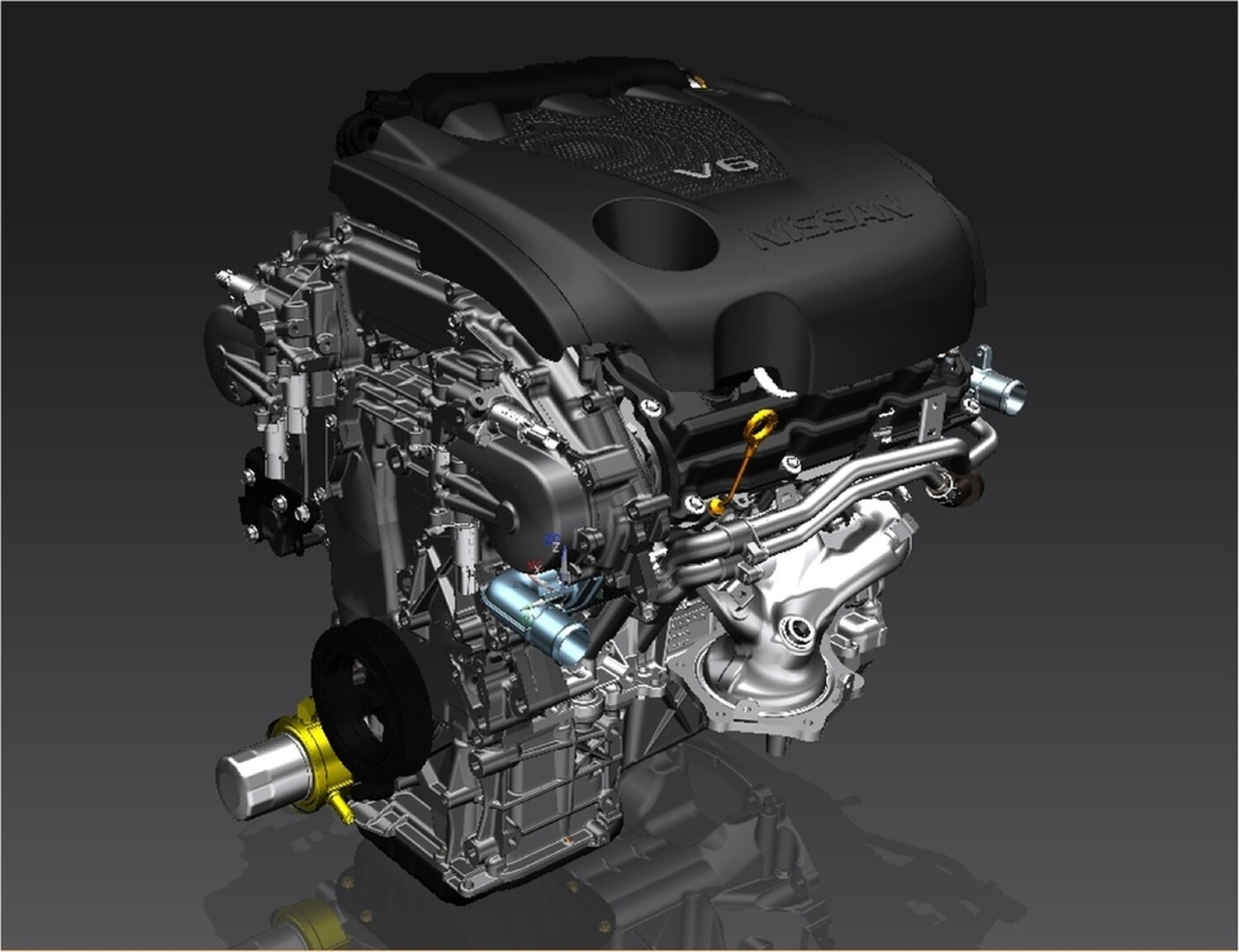
If you are considering upgrading your Nissan Maxima to a newer engine model, we recommend going with the 2016+ Gen3 VQ35DE Nissan. They have also come down in price and present a great option for a low mileage and newer engine. We’ve seen them as low as $850-$900 depending on mileage. There is also nothing wrong with considering a Gen2 VQ35DE (2009-2015) engine especially when you can get them at a much lower costs than Gen3. Ultimately, you make the decision on what is best, cost effective and convenient for you.
Overall, the 2016+ Gen3 engine has many new improvements over the previous 2009-2015 7thgen Generation Model Maxima. According to Nissan, the 2016+ engine has upgraded 61% over the previous engine. It also applies lessons learned and new technology from the legendary Nissan GT-R, such as sodium-filled valves.
Why it’s called Gen3 VQ35DE?
We’ve dubbed it the “Gen3 VQ35DE” to differentiate between the different years of the VQ35DE engine. When you hear Gen3, you know it’s an 8thgen 2016+ motor vs 7thgen.
2002-2008 – 1st Generation VQ35DE (5thgen/6thgen)
2009-2015 – 2nd Generation VQ35DE (7thgen)
2016+ – 3rd Generation VQ35DE (8thgen)
Engine Specs:
Key Improvements Include:
Reduced Friction and Weights
New Upper Intake Manifold
Intake Runners Are Shorter and Wider for Improved Flow
Exhaust Valves Are Sodium-filled — Just like on the R35 Nissan GTR, and Other High-end Sports Cars
All New Part Numbers in the Cylinder Heads and Valvetrain, All-new and Reconfigured to Encourage a High Degree of Airflow
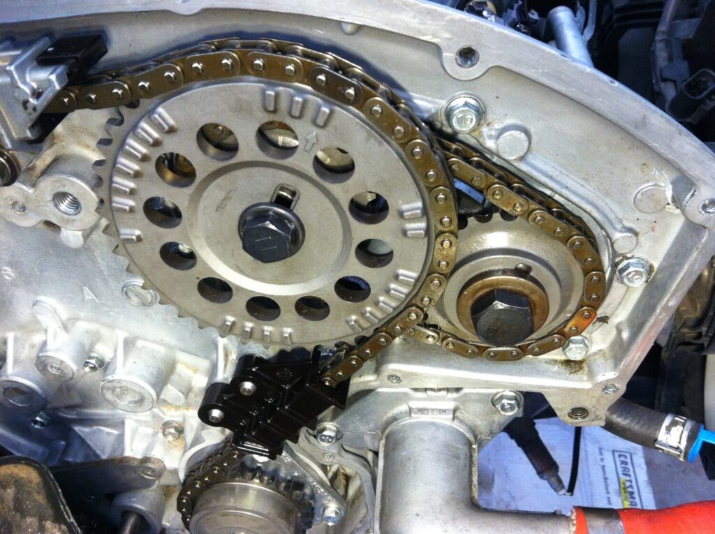
Timing Chains Driving the Valvetrain Are Redesigned with a Special Low-friction Design
Piston Skirts Are Anodized
Piston Rings Have a Diamond-like Coating Treatment, All to Reduce Friction
Oil Pump is Redesigned for Improved Flow
Oil Pan is Revised with Additional Ribbing to Reduce Noise Transmission
New High-flow Monolith Catalytic Converters That Reduce Exhaust Back Pressure
Swap Information:
The newer 2016+ 8thgen Motor has more solenoids than the previous 7thgen Motor. If you are putting this in an older Maxima, you need to hook up the solenoids noted in the photo.
2016+ Gen3 VQ35DE Swaps:
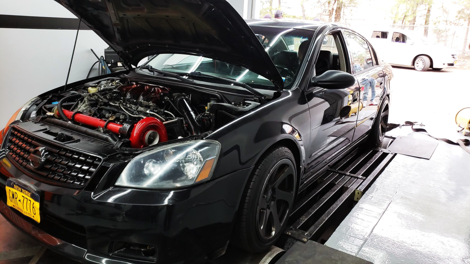
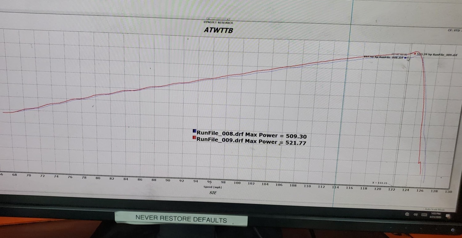
Notable Achievements on Gen3 VQ35DE
Altima SE-R – 521WHP GEN3 VQ35DE (UNOPENED), Tuned on UpRev by AdminTuning (No Cams or EVT)
Community Member Credit: Blackdiamond / 2002blackmax
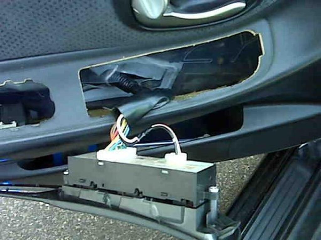
With the help of the technical service manual on CD produced by Nissan on the 2002 and 2003 Maxima I now have located the quick fix for a problem, I have had since purchasing my used 2002 SE a few months ago. That is the driver’s door window one-touch up function for the window was not working properly. The driver’s door window one-touch-up function was not working properly. The window would go up to the top and then retreat about 5 inches back down again.
This problem is due to the limit switch needs to be reset which at first I thought would be a considerable job (to take off the door panel etc.) but ended up being literally a 2-minute job as the door panel can remain in place.
I know several ‘02 and ‘03 Maxima owners have had this same problem but no one then appeared to know the fix. Although this procedure is simple once you do it, my description seems long, but I wanted to be a descriptive as possible.
So here it is:
Step 1: Pry the plastic cap up off the bottom center of the door pull handle and remove the single Philips screw.
Step 2: Remove the whole switch panel (in which the door pull handle sits) by prying it up from the back end either with a flat-edged screwdriver or table knife or by hand. It’s just clipped in, so should come out relatively easily. Sliding it up at the back and then pulling it back.
You can now see the inside of the door from where the switch finishing plate sat. You can leave the wiring all attached and simply hang the switch and handle plastic assembly to one side so you can see the inside of the door.
Look inside towards the front bottom of the door behind the plastic barrier. You will see a small black switch. It almost looks like a black pan screw head. This is the reset switch, but there is a sequence to now doing the actual reset procedure. The switch doesn’t really feel like one when you press it through the plastic barrier which incidentally you don’t need to cut (at least I didn’t). It is a switch that is only on when you are pressing it, otherwise, when released it is off.
STEP 3: Turn the ignition on so the windows are receiving power. Make sure the window is (up) completely.
Press the reset switch (keep it pressed in) and roll (down) the window completely (manually! -NOT with AUTO ONE TOUCH FUNCTION)
Release the reset switch. Then close the window completely (manually only! – NOT AUTO UP FUNCTION).
This is a very detailed post for those who want to understand the different solenoids on the 2016+ VQ35DE engine. This is also helpful to those who want to use both IVT and EXT and need help identifying which solenoids to use. Have seen some cases of members doing Gen3 swaps and not using the correct solenoids. #knowledgeispower
The 2016+ Maxima incorporates a Continuously Variable Valve Timing Control System for both the intake and exhaust camshafts. Using inputs from various engine sensors (engine speed, coolant temperature, camshaft position, etc.), the ECM controls the camshaft position using pulse width signals (duty signals) to four solenoid valves. This makes it possible to control the shut/open timing of the intake valve to increase engine torque in low/mid speed range and output in high-speed range.
Two Intake Valve Timing (IVT) control solenoid valves (one for each intake camshaft)
Two Exhaust Valve Timing (EVT) control solenoid valves (one for each exhaust camshaft)
50% Pulse Width:
At 50% pulse width, oil flow to both hydraulic chambers is blocked. Any oil pressure in the hydraulic chambers is retained. The camshaft is retained in the current position.
Pulse Width Higher Than 50%:
At pulse width above 50%, Pressure A oil flow is allowed into the Advance Hydraulic Chamber, operating the camshaft timing in the advance direction. The amount of oil flow/pressure is continuously variable based on the pulse width from the ECM.
Pulse Width Lower Than 50%:
At pulse width below 50%, Pressure B oil flow is allowed into the Retard Hydraulic Chamber, operating the camshaft in the retard direction. The amount of oil flow/pressure is continuously variable based on the pulse width from the ECM.
IVT System Diagram / Valve Timing Control Photo
EVT System Diagram / Valve Timing Control Photo
The intake valve timing intermediate lock control improves the cleaning ability of exhaust gas at cold starting. To help control cold-start emissions, the intake valve timing intermediate lock is used to fix the intake camshaft sprocket with two lock keys, keeping the intake camshaft timing at the intermediate phase while the engine is cold.
When the engine coolant reaches normal operating temperature, oil pressure from the oil switching valve overcomes the spring pressure and the lock keys are disengaged. The control vane is free to move the camshaft to the advance or retard phase, based on oil pressure from the oil control.
Cam phase is fixed at the intermediate phase by two lock keys in the camshaft sprocket (INT). Lock key 1 controls retard position and lock key 2 controls advance position.
ECM controls the intermediate phase lock by opening/closing the intake valve timing intermediate lock control solenoid valve to control oil pressure acting on the lock key and locking/unlocking the lock key.
Lock/Unlock Activation
When ECM activates the intake valve timing intermediate lock control solenoid valve, oil pressure generated in the oil pump is drained through the oil pressure path in the control valve. Since oil pressure is not acted on the lock key, the lock key position is fixed by the spring tension and the cam phase is fixed at the intermediate phase.
When ECM deactivates the intake valve timing intermediate lock control solenoid valve, unlocking oil pressure acts on each lock key. Lock key 1 is not released because it is under load due to sprocket rotational force. For this reason, lock key 2 is released first by being pushed up by unlocking oil pressure. When lock key 2 is released, some clearance is formed between lock key 1 and the rotor due to sprocket rotational force and return spring force. Accordingly, lock key 1 is pushed up by unlocking oil pressure and the intermediated phase lock is released.
The intermediate lock is controlled by the ECM using the intake valve timing intermediate lock control solenoid valve as follows:
A. When the engine is turned OFF (ignition switch is turned to the OFF position), the ECM turns ON the solenoid valve for a short time to drain oil pressure from the lock keys.
B. The lock keys are then pushed into the lock position by spring pressure.
C. When starting a cold engine, the ECM turns ON the solenoid valve to keep oil pressure drained from the lock keys; the intake camshaft is kept at the intermediate phase.
D. When the engine coolant temperature exceeds 140°F (60°C), the ECM turns OFF the solenoid valve, allowing oil pressure to push the lock keys to the unlocked position.
E. When the lock keys are in the unlocked position, normal (continuously variable) intake valve timing control is performed via the CVTCS.Note: The intake valve timing intermediate lock control solenoid valve is not a Data Monitor item.
When stopping the engine
When the ignition switch is turned from idle state to OFF, ECM receives an ignition switch signal from BCM via CAN communication and activates the intake valve timing intermediate lock control solenoid valve and drains oil pressure acting on the lock key before activating the intake valve timing control solenoid valve and operating the cam phase toward the advance position.
The cam phase is fixed by the lock key when shifting to the intermediated phase and ECM performs Lock judgment to stop the engine.
When starting the engine When starting the engine by cold start, ECM judges the locked/unlocked state when ignition switch is turned ON. When judged as locked state (fixed at the intermediate phase), the intake valve timing intermediate lock control solenoid valve is activated. Since oil pressure does not act on the lock key even when the engine is started, the cam phase is fixed at the intermediate phase and the intake valve timing control is not performed.
When the engine stops without locking the cam phase at the intermediate phase due to an engine stall and the state is not judged as locked, the intake valve timing intermediate lock control solenoid valve and the intake valve timing control solenoid valve are activated and the cam phase shifts to the advanced position to be locked at the intermediate phase. Even when not locked in the intermediate lock phase due to no oil pressure or low oil pressure, a ratchet structure of the camshaft sprocket (INT) rotor allows the conversion to the intermediate phase in stages by engine vibration.
When engine coolant temperature is more than 60°C, the intake valve timing is controlled by deactivating the intake valve timing intermediate lock control solenoid valve and releasing the intermediate phase lock.
When the engine is started after warming up, ECM releases the intermediate phase lock immediately after the engine start and controls the intake valve timing.
Solenoid Illustrations
The solenoids that you will use for your maxima swap areIVT Bank 1 and Bank 2 as highlighted in RED below.
The solenoids highlighted in purple are not used.
The solenoids in Green can be used if you choose to wire up EVT (a bit more complex).
This is the general diagram simple used by most for their Gen3 VQ35DE swaps.
These are high-quality parts and services from a reputable member. We’re thankful that after all these years we have someone still making these. Not to mention he is easy to work with and ships fast.
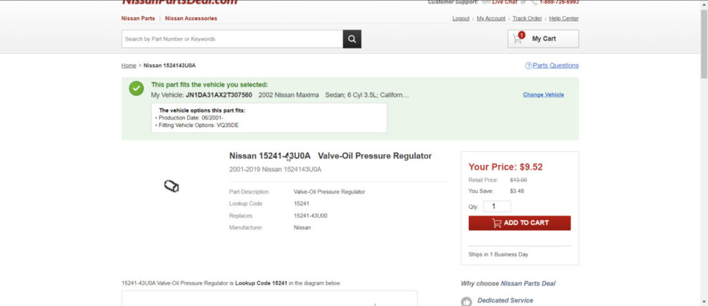
In working on my Gen3 VQ35DE for 4thgen Maxima, I ordered a new OEM Upper Oil Pan. The brand new pans do not come with the oil cooler pressure relief valve, so I ordered one. However, if you decide to use your old greasy upper oil pan, this is a good part to replace to avoid any issues with oil pressure. This is often overlooked. Read the below for more insight into this.
Part Number: 15241-43U0A Price: $9.00-$10.00
What does it do?
The oil pump maintains oil pressure to lubricate internal components. Most oil pumps are positive displacement pumps, which deliver more oil than an engine needs. To address this, there’s a pressure relief valve located at the oil pump outlet. Its purpose is to open when engine oil pressure reaches a certain value. A problem with the pressure relief valve can cause damage to the engine oil filter and to the engine itself.
Under normal pressure conditions, the oil pressure relief valve is forced down against a spring. As a result, oil goes directly through the pump to the engine. As oil pressure created in the system increases, the valve’s piston is forced against the spring causing it to open. This allows oil to flow back into the crankcase preventing excessive oil pressure. The spring tension of the relief valve determines the maximum oil pressure.
There is no sure way to prevent relief valve failure. In some cases, the valve just wears out over time. However, regular oil changes help prevent sludge and varnish build-up, both of which can cause the valve to stick. Changing your vehicle’s engine oil according to the maintenance schedule is the best way to prevent relief valve problems.
The pressure relief valve can be yet another cause of low oil pressure if the valve sticks open or is held open by a small piece of debris. The relief valve is designed to limit oil pressure as engine speed increases. The valve opens when the pressure reaches a preset value (typically 40 to 60 psi). This vents oil back into the crankcase and limits maximum oil pressure in the engine. The reason for doing so is to prevent oil pressure from reaching dangerous levels. Too much oil pressure can be just as bad as too little because excessive pressure can rupture the oil filter or even blow out pressed-in oil galley plugs in the block.
Alright, after tons of research on this subject, it would seem as though it is almost IMPOSSIBLE to actually complete the 95/96 to 97-99 steering wheel swap without any troubles. Of course, there are some, but the swap is actually fairly easy once you know what’s going on.
For those of you who have thought about trying this swap, it truly is fairly easy. I know many have run into problems and thought the only way to make this swap work was to replace more than just the steering wheel, but here is your way around it.
Parts/Tools Needed:
97-99 Steering Wheel
97-99 Airbag
95/96 Clockspring
**THE 97-99 CLOCKSPRING IS NOT NEEDED**
T50 Security Torx bit
Socket Wrench
Phillips Screwdriver
Flathead Screwdriver (to pop off covers around steering wheel)
Drill
13/64 Metal Drilling Bit
Dremmel tool (Or you can use a larger drill bit on the drill, see below)
Alright, once everything is gathered together, you are ready to start.
**Before going any further, DISCONNECT THE BATTERY**
Removing the steering wheel from the 95/96
Start by removing the plastic trim around the cruise control and the plastic door on the left-hand side of the steering wheel. Once removed, take a look and you’ll see two T50 security Torx bolts holding the airbag in place. Use the T50 security Torx bit along with your socket wrench to remove these two bolts. Once removed, pull gently on the steering wheel airbag, turn over, and disconnect the airbag wire harness. Set the airbag aside.
Now, directly in the steering wheel center, you will see a large nut holding the steering wheel to the hub. Remove this. Once removed, give the sides of the steering wheel a good whack. Try hitting it with the palm of your hand a few times in the 12-6-3-9 o’clock positions. Give the steering wheel a good yank, and it should pop right off. (If you prefer, you can use a steering wheel puller, but it’s not necessarily needed…)
Once removed, you should now see the clockspring.
We will now be underneath the dash and steering wheel.
Remove the fusebox door, and the entire thigh cover around the fuse box underneath the dash. Once removed, you should see a metal brace below the steering wheel. Remove this. Now, you should see 6 holes with Philips screws holding the black plastic around the steering column in place. Use a 4″ Philips screwdriver and remove all of these screws. The black plastic should now pop off, and expose the steering column, and the screws holding the clockspring in place. Before doing anything else, try to place the new steering wheel on the hub.
You will notice that the steering wheel does not line up with the clockspring. This is due to the slightly different 95/96 and 97-99 clockspring and steering wheel designs. You could use a 97-99 clockspring, but it will require more work and parts (such as the 97-99 hub, and yes, it is slightly different from the 95/96 hub). The clockspring for the 97 came with my steering wheel, and I can tell you that when you try to mount the newer clockspring, the mounting holes do not line up, and require the 97-99 hub to mount it.
So, for this writeup, we will be using the original 95/96 clockspring.
Remove the 4 screws holding the clockspring in place. Disconnect the clockspring harness underneath the steering wheel. Once removed, you can now test the fitment of the 95/96 clockspring to the 97/99 steering wheel. Line up the plastic square (the one where the wires are coming out of), with the square-ish hole on the backside of the wheel. As you can see, it ALMOST fits, but not quite. And, you’ll notice that hole for the nub on the clock spring is a little off. Here is where we do a little modification.
Take note as to where the hole for the clockspring nub should be. Mark it. This is where you will be drilling a new hole in the steering wheel for the nub to sit into. Drill very carefully, you do not want to ruin the steering wheel covering.
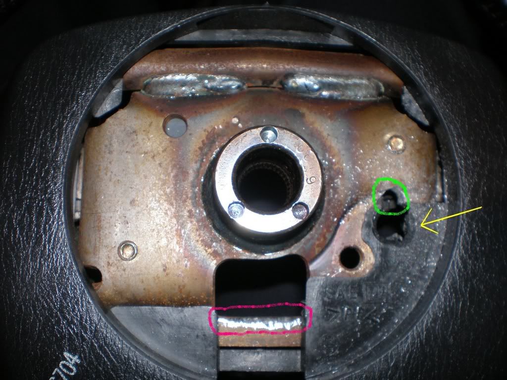
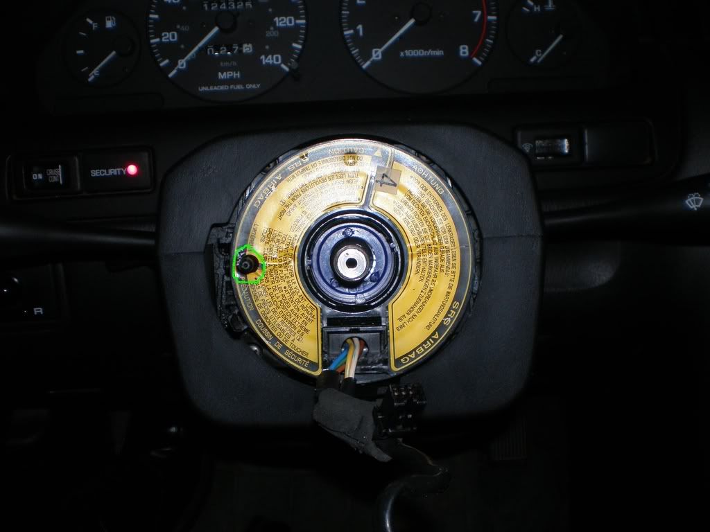
The green circle is the new hole on the 97-99 steering wheel that must be drilled to make room for the nub on the 95/96 clockspring. The yellow arrow is the hole for the nub on the 97+ clockspring; See how the hole is off?
The 95/96 nub we are drilling a hole for is circled in green, also take note of the blue trim ring around the hub. There are little pegs that will line up on the back of the shaft of the actual steering wheel. You will need to rotate this so that the steering wheel shaft holes line up with the pegs. When rotating the blue ring, make sure you keep the black square in the down position.
Once the new hole is drilled in the steering wheel, you can test the fitment again. The nub now goes into the steering wheel where you drilled the new hole, but the square plastic on the clock spring is a little too large to fit into the square opening on the steering wheel. This is where we will use a Dremel tool (or a small saw/knife, VERY CAREFULLY as you do not want to cut the wires coming out of the square). You will want to trim down the bottom quarter-inch of the plastic square. This will give the clockspring the clearance to sit nice and flush with the back of the steering wheel.
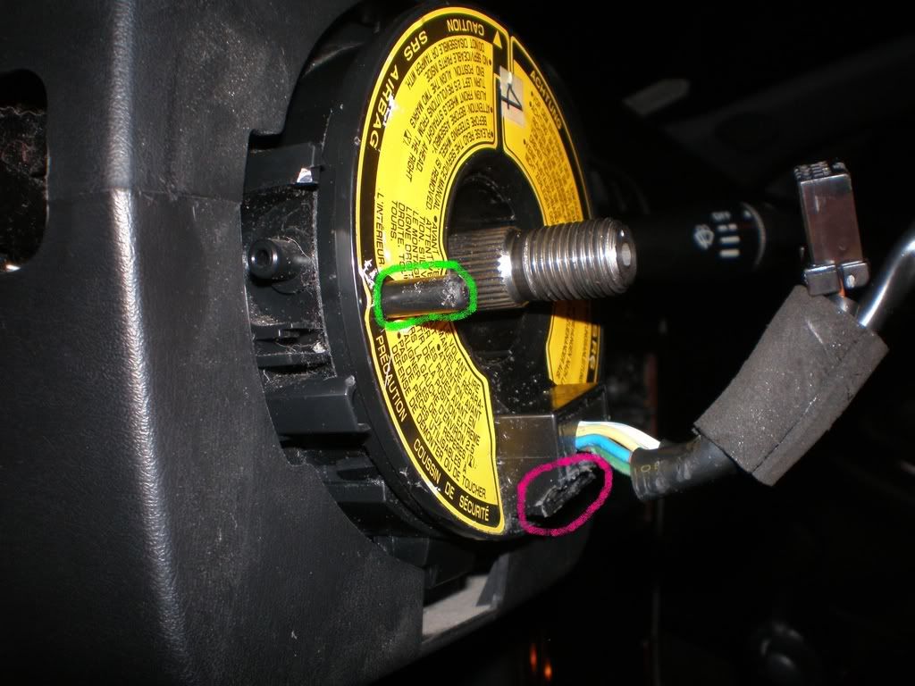
The area of the plastic square that must be trimmed is circled in purple. It now looks like a little step. The nub we drilled a hole for in the steering wheel is circled in green
Here the purple circle shows the area where the 95/96 clockspring won’t clear without the clockspring trimmed. Once the clockspring is trimmed into a stair, and the hole for the nub is drilled, the back of the steering wheel will sit flush with the clockspring.
Voila! You have now slightly modified the 95/96 clockspring to fit the 97-99 steering wheel.
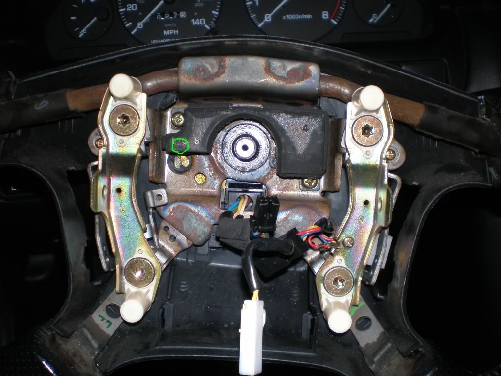
The green circle is where the nub is, you cannot see it here due to the black plastic covering the hole. Also, notice this image shows how the steering wheel will line up in the straight position due to the position of the plastic square on the 95/96 clockspring lining up with the square hole on the 97+ steering wheel. As you can see, the steering wheel is also sitting on the hub and clockspring, nice and flush.
You can now reassemble the clockspring to the hub, and the plastic trim that goes around it. YOU NEED TO CENTER THE CLOCKSPRING WHEN REINSTALLING IT. Do this by starting with the plastic square in the down position. Turn the clockspring to the left or right until it tenses up. This is the endpoint of the motion of the clockspring. DO NOT FORCE IT PAST THIS POINT, IT WILL BREAK! You should be able to start in the down position and turn it left and right 2 full turns until you reach the tension point. Once you are sure you can turn the clockspring in both directions the same amount of turns, make sure you reconnect the clockspring to the wiring harness underneath the steering wheel. Only when these steps are completed, you can now place the steering wheel up the clockspring, making sure the wheel is straight. The clockspring nub goes into the new hole, and the black square goes into the square-ish opening on the steering wheel. You might have to play with it a little to make the steering wheel sit flush on the clockspring/hub. You will see a little blue ring that has three nubs that fit inside 3 holes on the backside shaft of the steering wheel. These need to be lined up too. Now, reuse the large nut used to hold the steering wheel to the hub, making sure it is nice and tight. You do not want the steering wheel to slip while driving!
Run the airbag/cruise control wiring harnesses through the backside of the steering wheel and connect the 97-99 airbag harness and the cruise control harness. Use the T50 Torx bit to reinstall the Torx bolts to hold the airbag in place. Snap-in all of your black trim doors/covers around the steering wheel. Reconnect the battery and turn on the key. Your airbag light should come on and start flashing. Don’t worry! You just need to reset it.
To reset the airbag light, turn the key to the ‘on’ position. Locate the little door button sensor below the B pillar. Press this 5 times as soon as you turn the ignition to the ‘on’ position, let any codes go by, and turn the ignition ‘off’. You may have to repeat this a few times, but the light should now go away and not flash.
TAKE NOTE THAT THE 95/96 CLOCKSPRING MUST BE SITTING IN THE CENTER POSITION WHEN MOUNTING THE 97+ STEERING WHEEL! IF NOT, THE CLOCKSPRING WON’T HAVE ENOUGH SLACK TO TURN FULLY LEFT OR RIGHT, AND WILL BREAK! I AM NOT RELIABLE FOR YOUR MISTAKES!
Here is the center position of the 95/96 clockspring on the hub. If you use the bottom square as your marking point, from this position, I can turn the clockspring about 2 full turns to the left, or 2 turns the right. This means that the clockspring will turn the full 2 turns, and start to “tense up” just as the square is about to go past this point a third time.
There you go. Patients and confidence will allow this to happen. Enjoy!


")

")


")


 and Exhaust Variable Timing (EVT) Solenoid References")


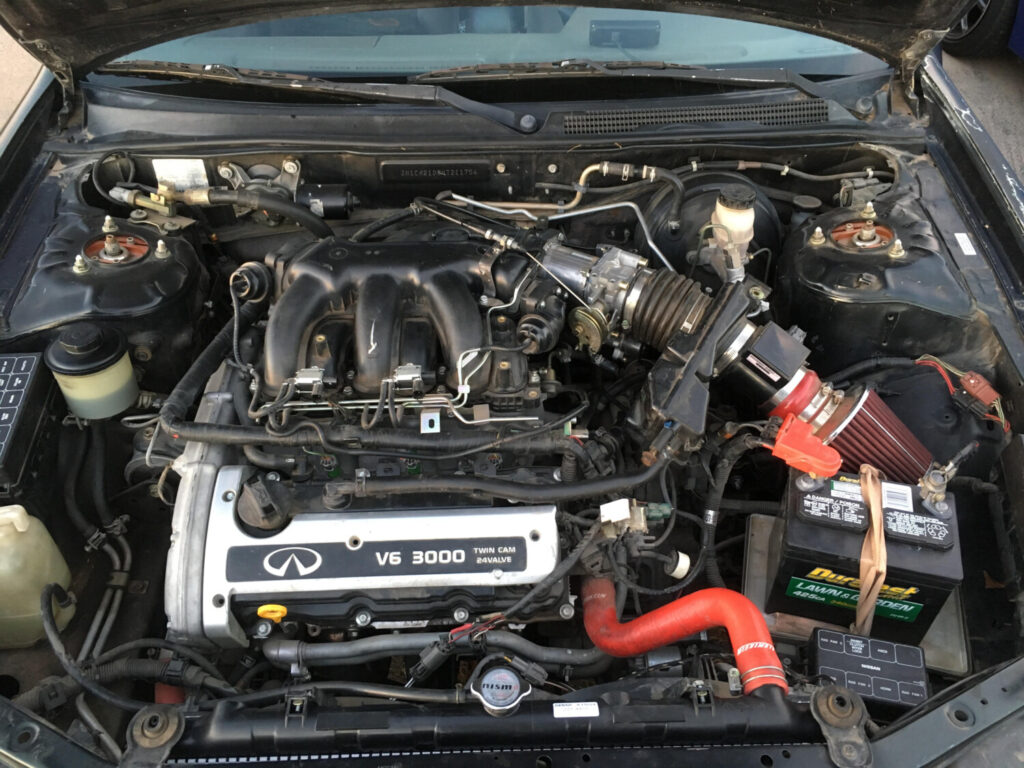
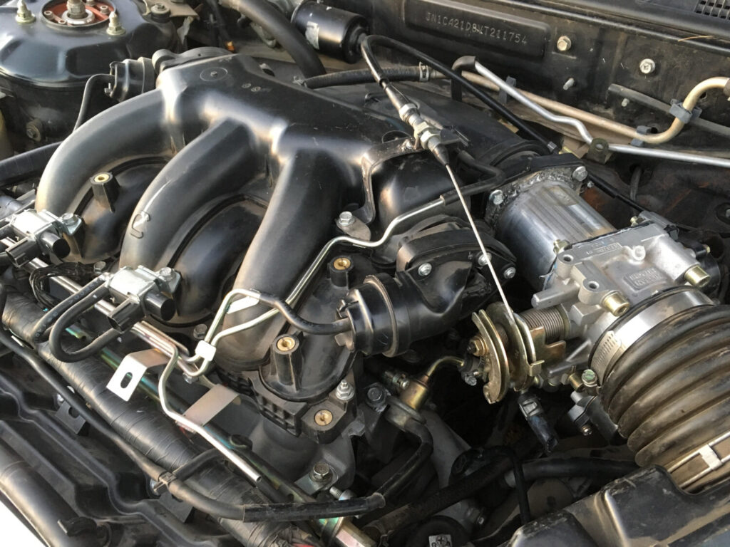
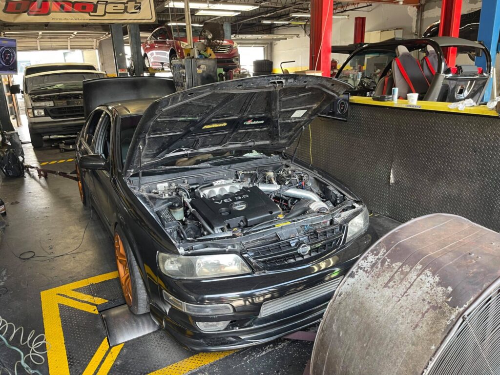
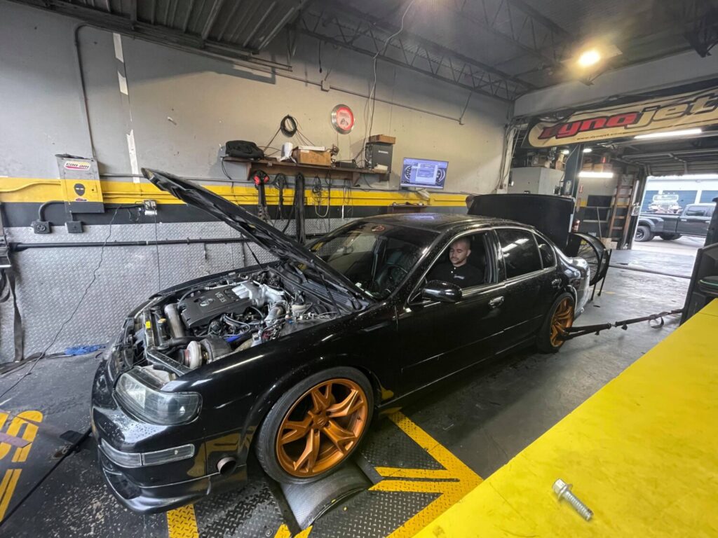
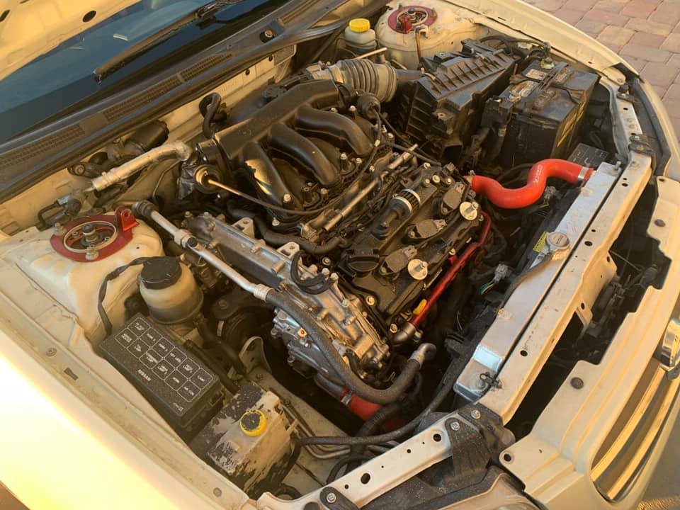
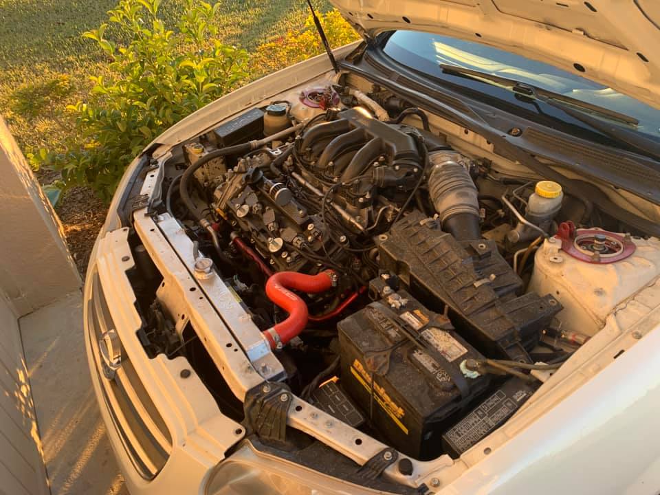
 Leonard’s Engine Bay