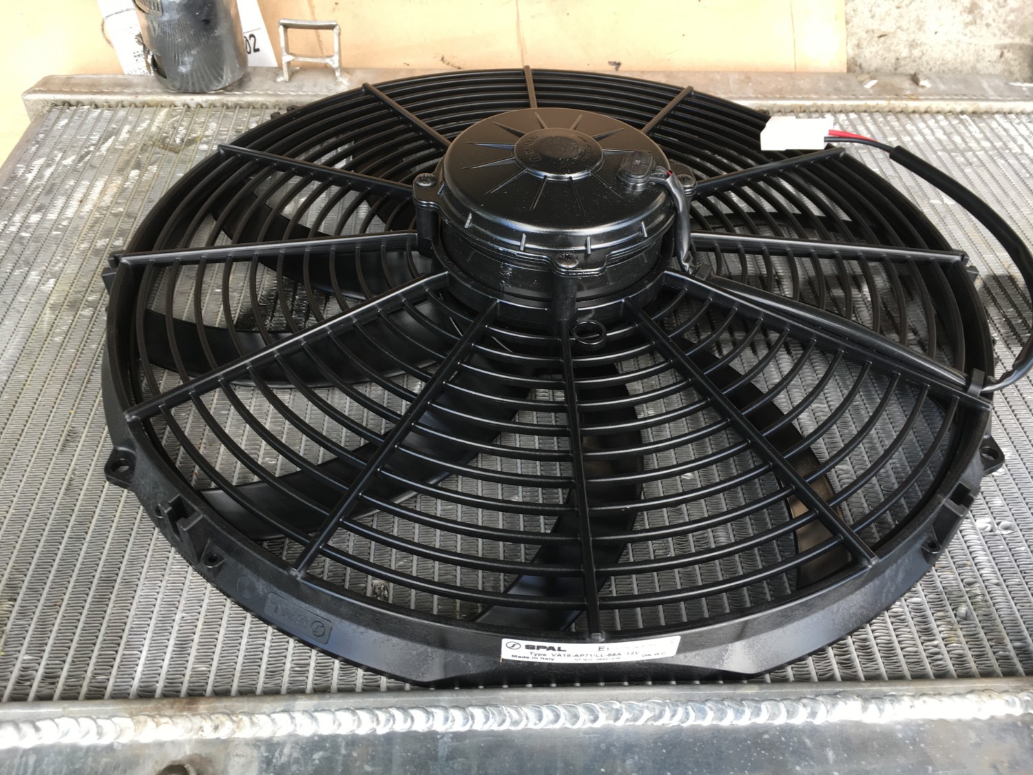
This post if for folks looking to install SPAL Fans into their Maxima. These are quality high-speed fans that are great for both N/A and Boosted Setups.
We designed the SPAL fan wiring harness to enable the simplest installation of our performance fans. It is compatible with all types of vehicles and can be installed on positive or negative ground vehicles with no modifications
185 Degree Thermostat Controlled Relay (185FH)
195 Degree Thermostat Controlled Relay (195FH)
Installing the fan:
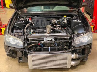
When installing electric cooling fans, it is important to cover as much surface area as possible. Mount the fan as high up on the core as possible. Attach the fan to the small area around the core of the radiator where there is a metal lip that is approximately 1/4″ to 3/8″. This will allow mounting of the fan(s) without compromising the core of the radiator.
Wiring:
Mount the relay in a secure place in the engine compartment away from heat sources. Once this is completed, connect the wires per the diagram and notes below.
Red: Connect to the red wire of fan pigtail with pre-terminated yellow crimp.
Gray: Connect to thermostat socket (sending unit) with blue ring crimp connector.
Yellow: Connect to positive battery terminal using the fuse holder and yellow crimp connectors per diagram (see back).
Orange: Connect to ignition switch +12 vdc when engine is in run position. (Hook to constant +12 vdc for the fan to run continuously when the engine is hot even when the ignition switch is off).
Black: Connect ring terminal to chassis ground.
Fuse Holder: Connect fuse holder inline per diagram within 12″ of the battery using ring terminal or equivalent.* Note: On medium profile fans use a 20 amp fuse, on low profile fans use a 15 amp fuse
Installing the Thermostat Switch:
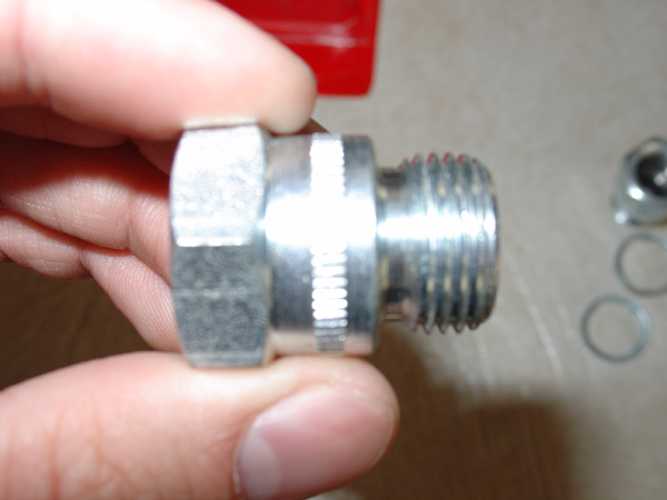
The sensor has 3/8″ pipe thread. The thermostat supplied with the kit is an OE type that is designed to mount in the cylinder head of the engine. However, any mounting in water jacket is suitable. The 195FH sending unit comes on at 195 degrees and off at 175 degrees. The 185FH module turns on at 185 degrees and off at 165 degrees. The modules will work on the majority of applications. If a different size adapter is needed, the correct size thread adapter can be found at most automotive parts or hardware stores (1/2″ adapter included in the kit) . Do not use Teflon tape on the sensor it can cause poor electrical contact and incorrect temperature readings.
Wiring Diagrams
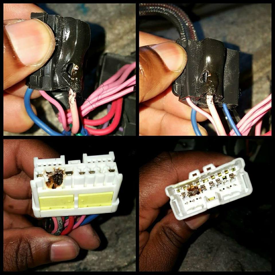
If you don’t use a good relay like the one above, this will happen (Photo Courtesy of Javon Bennet)
I was finally able to get a hold of Brian who made this song back in 2009 for the Maxus09 event. I couldn’t find it for years. But here it is. This deserved its own official post.
If you are reading this article, you are very likely trying to resolve P0420/P0430 without having to spend a lot of money on the issue. Most of the time, the codes are due to a bad clogged catalytic converter or bad O2 sensors. Before replacing the O2 sensor, be sure to do the spacer fix modification first because O2 sensors are not cheap.
There aren’t usually any drivability issues associated with these codes. For most people, the first sign that anything is wrong at all is the check engine light. Below are the typical check engine lights you would normally get:
P0420 NISSAN – Catalyst System Efficiency Below Threshold Bank 1
P0430 NISSAN – Catalyst System Efficiency Below Threshold Bank 2
The Fix
You can eliminate the codes by using a spark plug non-fouler which tricks your engine computer to think that everything is working fine. This simple trick will pull the O2 sensor away from the exhaust flow and the computer will think the Catalytic converter is working properly. This will work if you remove the catalytic converter or have a bad cat. It’s very simple and cheap to do. Below is a video on how to perform the fix:
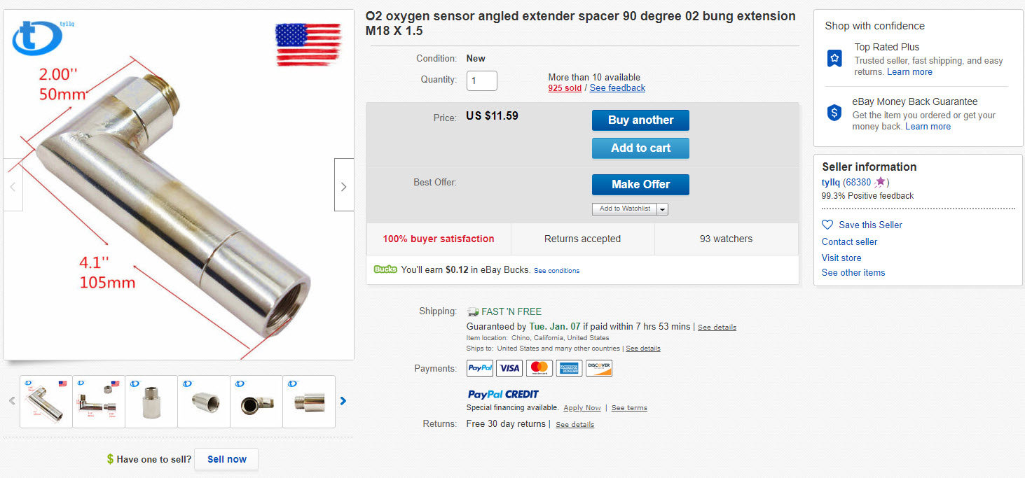
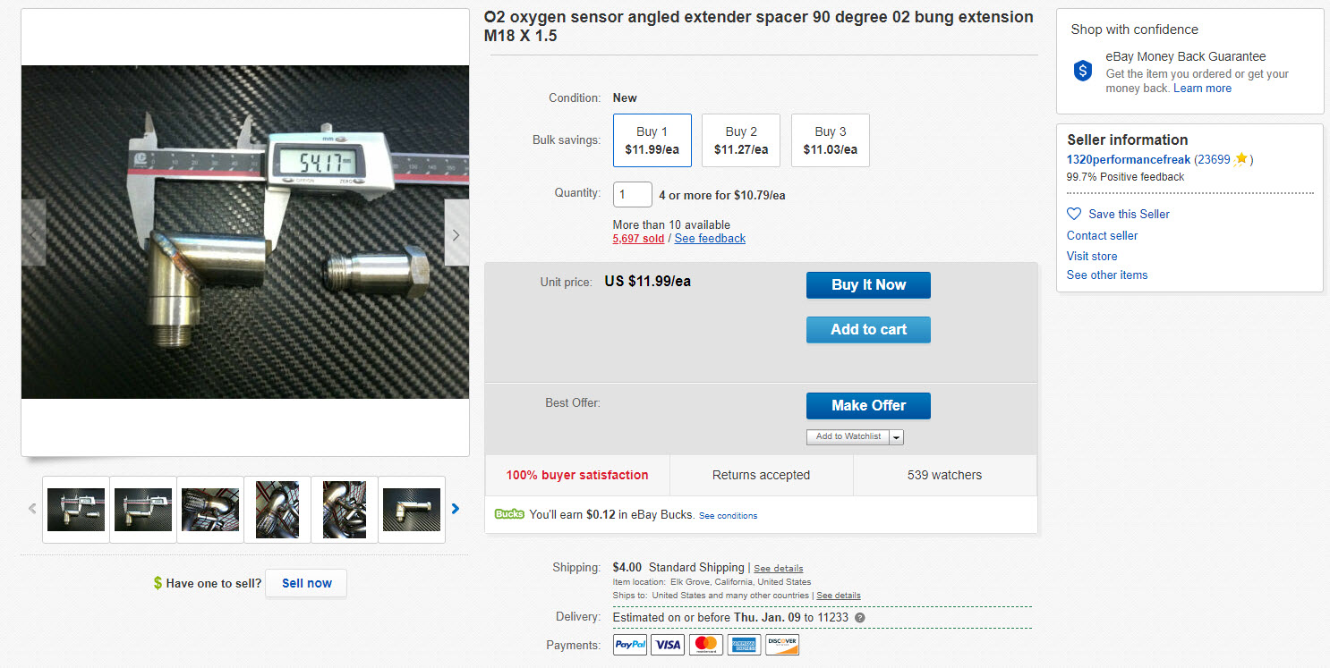
You can also buy them pre-made on eBay if you do not want to drill.
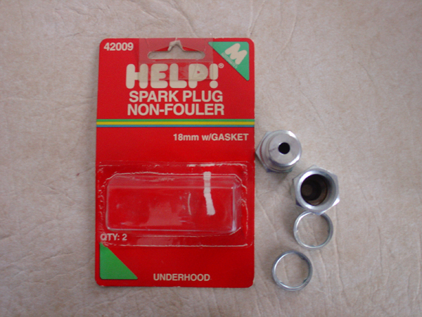
Make Your Own Spacers/Foulers
You can buy these non-fouler spacers at your local parts store. You can get them from Advanced Auto or Autozone for about $7-8 bucks.
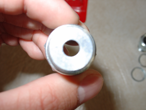
You now need to drill out 1 of the non-foulers using a 1/2″ drill bit. When finished this is what it will look like.
O2 Sensor inserted in the modified non-fouler
Second, unmodified non-fouler now installed on modified non-fouler, then threaded into the pipe
Reference Photos
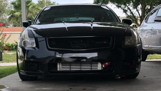
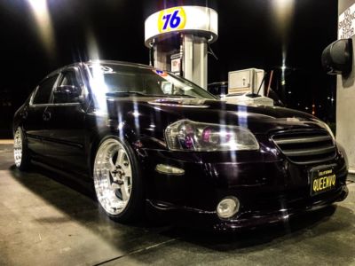
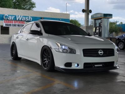
Below are photos of the spacers installed and 100% working on Nissan Maximas by generation. After installing the spacers, the CEL codes went away.
Below is the wiper size chart for your Nissan Maxima. On my 2004 6thgen Nissan Maxima, I went with RainX Conventional Expert Fit wipers. I’ve included a photo below. They work well and got them both for around $18 bucks at Walmart.
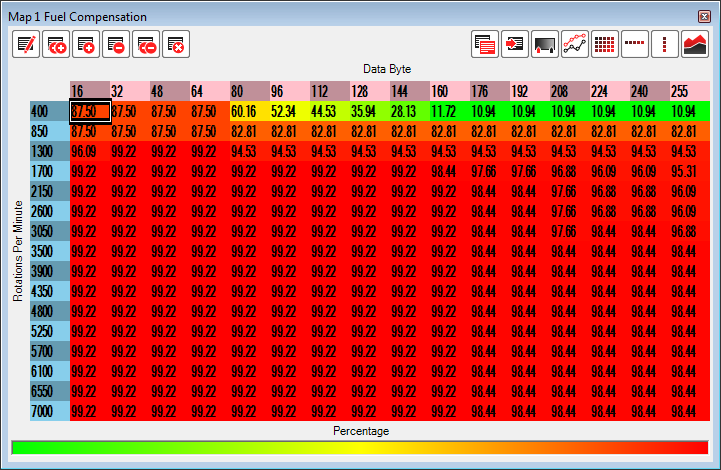
THESE TABLES ARE FOR A VERY SPECIFIC F/I SETUP! I’m running GT25 twins with 600CC DW’s, AAM basic fuel return, and HPX MAF. Don’t be stupid and start making power pulls with these tables on YOUR setup. Tune it right and use these values as starting points if you want.
This tune actually took me almost a year to perfect a little here, a little there, learn from mistake and start over and repeat, ect ect. Some so-called ‘tuning shops’ and even exhaust parts and turbo kit manufacturers could learn alot from this post.
As of now it’s running perfect in every way from startup, mid throttle, and WOT. A/F in close and open loop are right on target. As you can see, most of the fuel work was done on the MAF table. Basically the car drives exactly like stock in and out of boost, with zero misfire.
If you’re not running a fuel return system, you’re going to be rich at low loads, and lean out hard in higher loads with this map so be aware! If you are running a return setup, set your base pressure to 48psi (or adjust the K accordingly to your pressure).
FYI I made 400whp with this tune at 8.3psi and power all the way to 7krpm in 108 degree ambient temps and major heatsoak. And I’m also running cats, so there’s probably more power to be had.
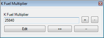
K fuel adjusted for my base pressure and injectors:
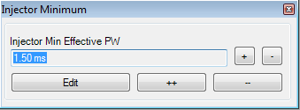
Injector minimum for DW 600 IMPORTANT that you upgrade to the latest ROM editor, as the older versions apply the wrong values:
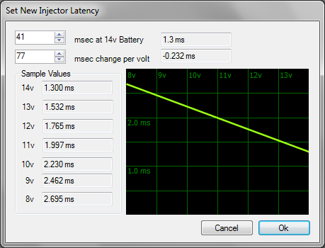
Latency for DW 600 – IMPORTANT that you upgrade to the latest ROM editor, as the older versions apply the wrong values:
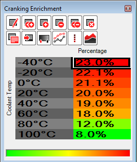
Startup enrichment – you need to pull ALOT from here especially at the bottom:
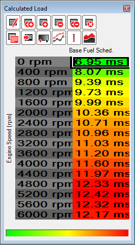
Load table (needed for 5AT only — I did it anyways so my logs looked better). Once you dial in your max fuel schedule on the fuel tables, adjust this so you’re hitting 100% whenever you’re in boost. If you don’t do this correctly, the torque converter will not lock up and it will granny shift to an early demise:
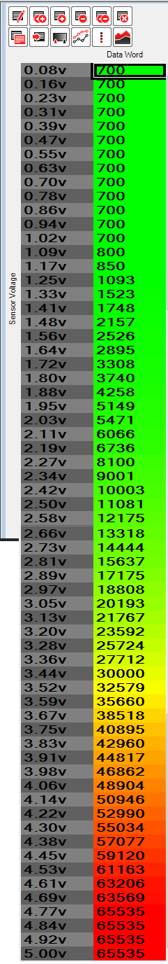
MAF table for my HPX MAF — IMPORTANT – If you don’t have a fuel return system, these MAF values will NOT be a good base map for you to start with, in fact it will make life more difficult!!! start with the Uprev tuned HPX MAF table instead. This table is where I spent most of my time. Yours will flatten out at a different lower voltage since they suck bawls at idle. It’s a delicate balance of fuel compensation and flattening to keep the A/F from bouncing at idle. At first, I tweaked the idle and free revving voltages manually by going over logs and making manual adjustments. Once it was somewhat drivable (out of boost), I took some logs of driving around normally and started making adjustments with my maf tool. Eventually I did a super rich boost pull and made more manual adjustments in the boost voltages. Once I was in the ballpark, I again used the maf tool to get the A/F exactly where I wanted it at all boost levels.
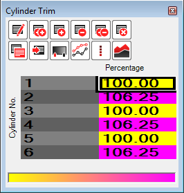
Cylinder trim — I’m glad uprev included this, because I was running about 0.6 a/f leaner on bank 2 in boost which required 6% increase in fuel for bank 2 to iron out — you should probably skip this at first and see how far your banks are off in boost before adjusting.
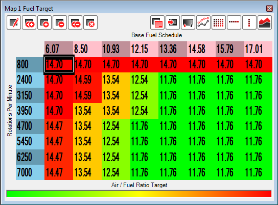
Fuel target — this has been adjusted with F/I and stock block in mind. take CAREFUL notice of the fuel schedule on the horizontal axis! You need to change the maximum value on the axis, then use the linear interpolation button on the whole row to smooth it out. This has to be done to timing table too! This DOES NOT happen automatically! If you changed your redline, do the SAME THING to the RPM column! The actual max fuel schedule totally depends on your fuel system. Yours will be higher without a fuel return, or with smaller injectors. On your first WOT pull, see how far the cursor goes to the right and adjust until it gets at least 80% across the table.
Fuel comp – I made most of my adjustments to the MAF table (manually to get in ballpark, then finished off using my tool http://djlab.com/uprev/maf.php) so the fuel table is mostly flat except for idle and cranking trims:
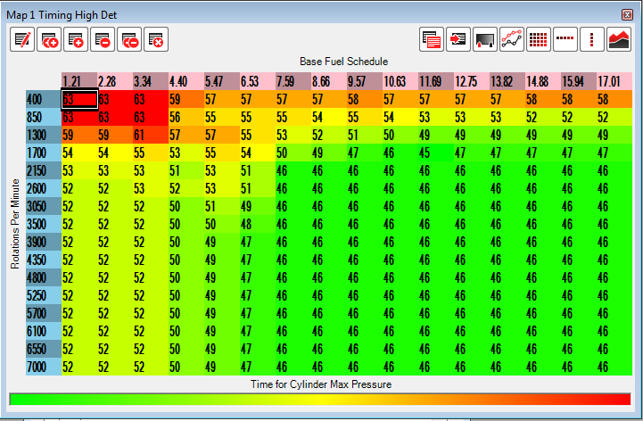
Timing main – Be sure to adjust the fuel schedle accordingly just like the fuel target table. Also, don’t run this high of timing unless you have knock headphones and know what to listen for. This map starts around 13deg at 3krpm and reaches 17deg at redline at 9psi (you should start with less!). Notice how it is smoothed out in the low-load areas so there isn’t a big jumps in timing in any direction. The key is no big jumps in values, because the ECU doesn’t like that and you will end up with instability. IMPORTANT If you run too low of timing in low load (left half) you can end up with a ‘danger to manifold’ situation as EGT’s will go thru the roof!:
Timing hi-det – copy and paste the main timing and subtract 4-5 from everything:
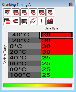
Cranking timing (A Table): Adding some timing at higher temps on the A table seems to help with warm starts.
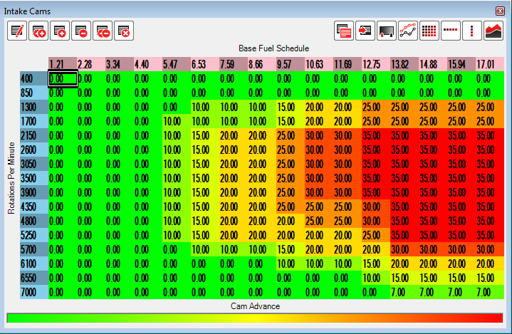
Intake cams – RPM’s are scaled and cam advance is mostly stock, except extended for the new redline:
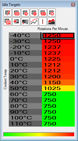
Idle targets (slight bump):
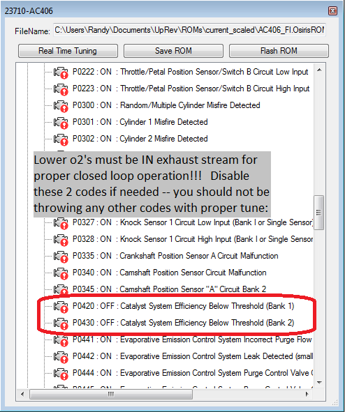
DTC disable – You should ONLY have to disable the two catalyst codes. If you throw any other codes, you’ve got a problem with the car or your tune. Misfire codes or codes of any other type should NOT occur with proper tuning and all sensors in place. In my year of struggling with this ***** of an ECU, I learned through trial and error the lower o2’s play a big role in closed loop operation. If you have them removed from the exhaust stream with non-foulers, steel wool, or simply tied up (like on the momentum kit) you’ll have issues dialing in your closed loop trims and may even throw bank range/lean/rich codes with an unstable A/F over time:


")


")
")


 Event")


")