Order Link: https://racespeconline.com/collections/connector-kits/products/gtr-sumi-3-pin
Includes
- Housing
- Lock
- (4) Terminals
- (3) Seals
Fits
- Nissan R35 GTR Ignition Coils
- Other Nissan Coils
- Some Mazda Coils

![]()
Order Link: https://racespeconline.com/collections/connector-kits/products/gtr-sumi-3-pin
Includes
Fits

![]()
Source Credit: https://www.facebook.com/NissanSmyrna
Last week, Nissan team members celebrated the last Maxima to roll off of the Smyrna assembly line!
Over the last 20 years, the Maxima has helped establish Nissan as a key player in the global auto industry, Smyrna as one of North America’s finest manufacturing plants, and our team members as some of the best technicians on the planet.
Virtually every Nissan Smyrna employee has played a role in creating the Maxima’s legacy. Since the start of Maxima production (all the way back in 2003!), there have been a total of over 1 million Maximas produced. But despite that large quantity, quality never slipped. In fact, throughout the course of its production, the Maxima won five different manufacturing-related J.D. Power awards, including being named the “Best Overall Model” in this year’s J.D. Power Initial Quality Study.
Smyrna is proud to have been the home of Maxima for 20 years. And as we roll forward, the legacy of the Maxima and the team members that built it will go on to inspire the bright future of Nissan Smyrna!


![]()
This post is dedicated to Mike. We met him at one of our ECM event where he drove his Maxima with freshly custom painted engine day. He was so excited and happy to show off this hard work. He truly loved modding his 4thgen Nissan Maxima. This is such a devasting and tragic loss for the Nissan Maxima community. You will be greatly missed Mike!
Mike passed of health related causes at only the age of 32. He had an infection in his brain caused by Listeria Rhombencephalitis, which can mimic stroke like symptoms. If you don’t know about Listeria anyone is susceptible. You can learn more on it here: https://www.cdc.gov/listeria/index.html
Contributions: https://www.gofundme.com/f/michael-troutman
We send our deepest condolences to his friends and family. Gone but never forgotten!


![]()
Credit: Luke Melton
ECUMASTER EMU BLACK is a universal engine control computer that manages the operation of spark-ignition engines, and is designed to work with the most advanced and complex currently available engines. It is the successor to our proven system, the ECUMaster EMU. Common applications for the EMU Black are modified race cars, passenger cars, motorcycles, boats, and stationary engine applications.
Notes:


![]()
Member Credit: schmellyfart
I was reading one of Nissan’s technical documents on the HR engine and its improvements HERE when I came across this:
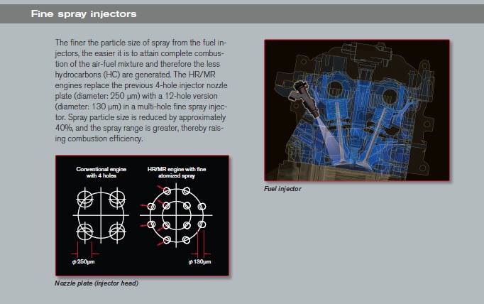
Which then had me wondering if these improved injectors flowed less fuel in FWD applications compared to RWD applications as they did with the First generation VQ35DE. In addition to the flow rate, I was also interested in seeing how the injector spray patterns compared with the different hole configurations.
I had an ASNU Classic Injector Flow Bench at my disposal at school, so I finally took advantage of it, and cleaned & flow tested a handful of injectors to say the least.
Injectors tested:
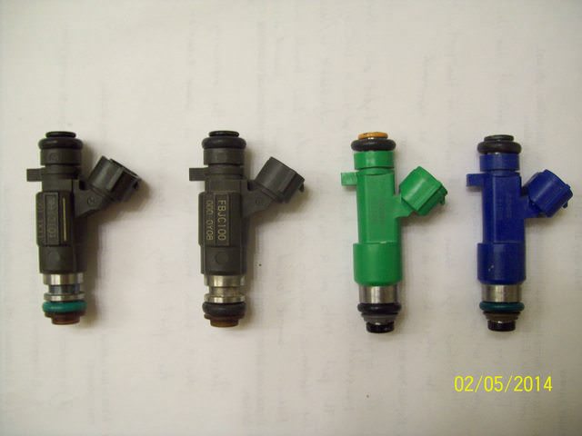
Test Procedure:
I wasn’t able to take clear pictures of the holes in the injector nozzle plate. So this description will have to do.
FBJC100 – 4 hole
FBJC101 – 18 hole
Green Denso – 12 hole
Blue Denso – 12 hole
Results
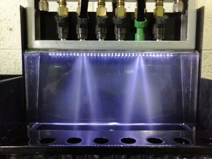
FBJC100 left, Green Denso right
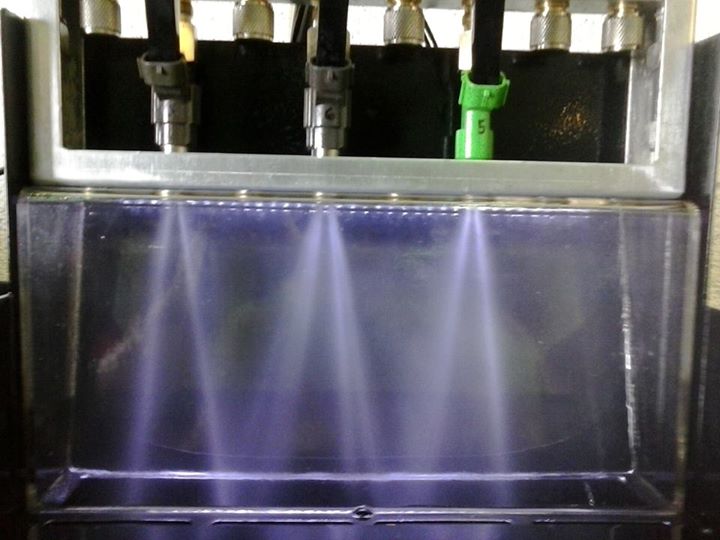
FBJC100 left, FBJC100 middle, Green Denso right
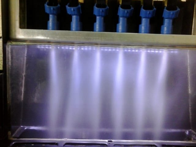
Blue Denso
I also recorded videos of pulse testing as well.
Static Flow Test Results at 3 bar:
FBJC100 – 306 cc/min
FBJC101 – 294.25 cc/min
Green Denso – 309.25 cc/min
Blue Denso – 546 cc/min
To sum it up, the Green Densos in the newer VQ35HR and HR styled 09+ VQ35DE have the same flow rate. At that, they only flow a tiny bit more fuel than the FBJC100, but have better atomization. The Green Denso injectors are also lighter in weight than the FBJC100 at 0.070lb each for the Green Denso, and 0.098lb each for the FBJC100.
![]()
Credit: Noah Vella
I had trouble finding a decent OEM type option so I hope this helps a few people out. I was originally going to wrap the chrome black but it actually matches the e-brake button, Nissan emblem and door handles so I think I’ll keep it chrome.
Shift knob:
You can find these on online (eBay) between $15.00 to $20.00 shipped from China. The common search words are “6 Speed Gear Shift Knob For Nissan X-Trail T30 2001 2002 2003 2004 2005 2006 07″.
You will need this adapter:


![]()
Original Source Credit: http://www.nisformance.com/Articles.asp?ID=252
This article shows how to swap a 2007+ Altima 3.5L VQ35 engine, or 2009+ Maxima 3.5L engine into older Nissan Maxima’s. Including the 2002-2006 Altima (3.5L) and 2002-2008 Maxima’s. This motor swap is referred to as the 2nd Generation (Gen2/Gen3) VQ35DE swap.
There are three generations of the front wheel drive VQ35DE engine.
2nd Generation VQ35DE Swap Kit ($230.00)
Order Link: http://www.nisformance.com/2nd-3rd-Gen-VQ35DE-swap-kit-p/hrkitv2.htm

EPS Tuning Oil Gallery Gasket/Hardware Kit 2nd Generation VQ35DE engine ($60.00)
Order Link: http://www.nisformance.com/EPS-Tuning-Oil-Gallery-Gasket-Hardware-Kit-p/oilgallerykitfwdhr.htm

There are a few things to keep in mind before beginning your swap:

Depending on where your motor came from, there may be a lot of ‘extra’ pieces still attached to it. Some of these will just get in your way while you prep your motor, some can’t be used for this swap.

 ** The injector rail may also be removed, but that isn’t necessary.
Some parts of the motor will need to be cut somehow (tools, methods and results will vary) to allow for proper fitment and function once it’s reinstalled.
** Because of some concerns about the integrity of the stock oil gallery gasket, we at NISformance strongly recommend replacing it in this step. **


*Please note that we now offer a completely bolt on trigger wheel that eliminates the need to modify your stock trigger wheels*

If you choose to modify your stock trigger wheels, please note that this is a VERY important step and it must be done very carefully for your car to run properly. You have to be extremely accurate.
Apart from the wiring, adjusting the signal wheel is the most detailed work you need to do on the swap. It is important to be very accurate when cutting or grinding, and it’s also extremely important to assemble everything correctly at the end of this step. Pay close attention to the pictures and make sure that your work looks EXACTLY the same!
*You will need to modify your 5/16 Allen key by cutting the arm down so that it is approximately 3/8″ long. This is your ‘special tool’ that you will need to use in this part of the swap.


V2 inverters are single channel. One inverter is required for each camshaft position sensor.
Wiring for cam sensor signal inverter
Picture below demonstrates the older style DE cam sensor plug that is cut off when wiring in inverter with required wiring

The wiring harness in your car needs to be connected to the newer motor, and it’s not just a ‘plug-and-play’ situation. These diagrams show you the changes that need to be made to make your DE harness control your HR motor:

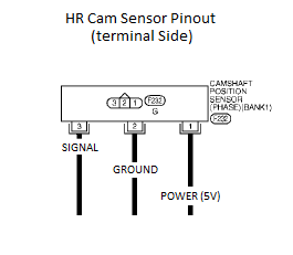
** THESE WIRE CONNECTIONS ARE CRITICAL. MAKE SURE THAT THEY ARE CONNECTED CORRECTLY (ACCORDING TO THE INSTRUCTIONS), AND SECURELY. TWISTING THEM TOGETHER IS NOT GOOD ENOUGH. **
The stock cam signal wire will be intercepted (cut) by the cam signal inverter supplied with the swap kit. There are six wires on the cam signal inverter…here’s how you connect them:
For Cam #1…cut the existing wire:
For Cam #2…cut the existing wire:
![]()
Credit: Noah Vella


![]()