Year: 1989
Model: Maxima
Color: White
Transmission: Automatic
Trim: GXE


![]()


")
Owner: Cilcil88
Year: 1989
Model: Maxima
Color: Black
Engine: VG30DE
Transmission: 5-Speed Manual


![]()

 Credit: Jodi Breci
1992 GXE gifted to my son by my aunt today. Never been driven in snow and just a couple days of rain. Always garaged. Original paint is so shiny still! 78K mikes. Too bad it’s not a manual.


![]()

Owner: Cesar Silva
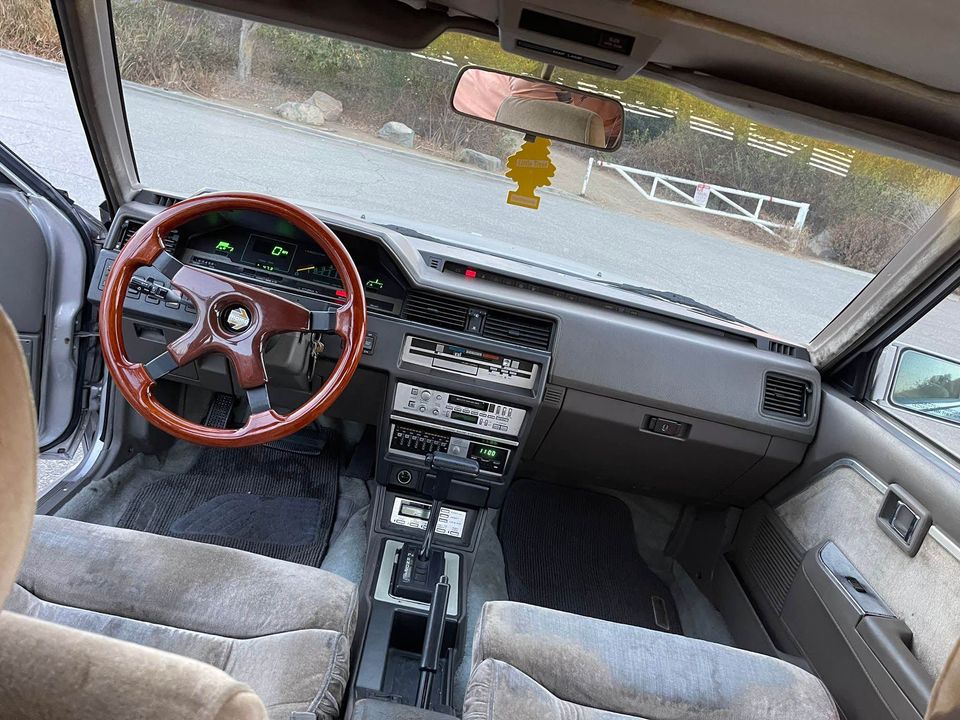
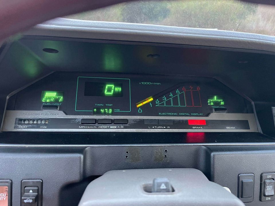
Year: 1986
Model: Maxima
Color: Silver
Transmission: Automatic
Trim: GXE


![]()

![]()
")
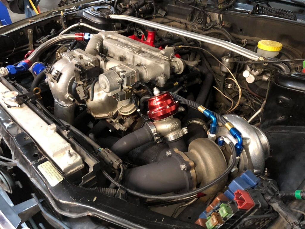
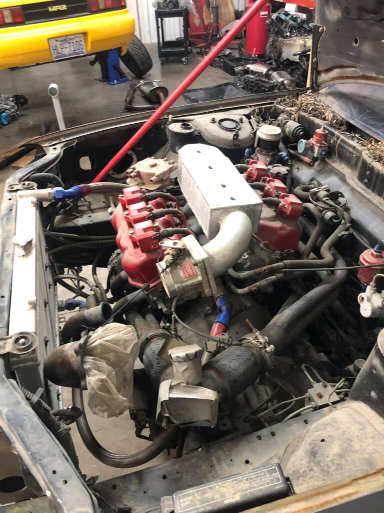
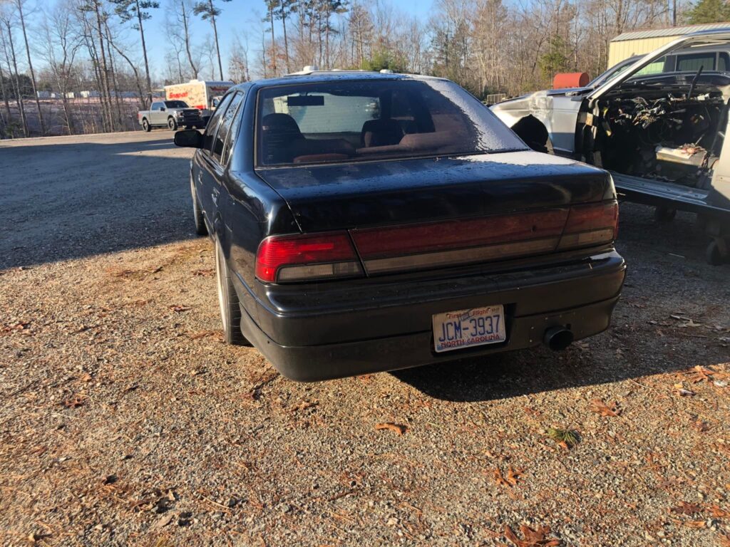
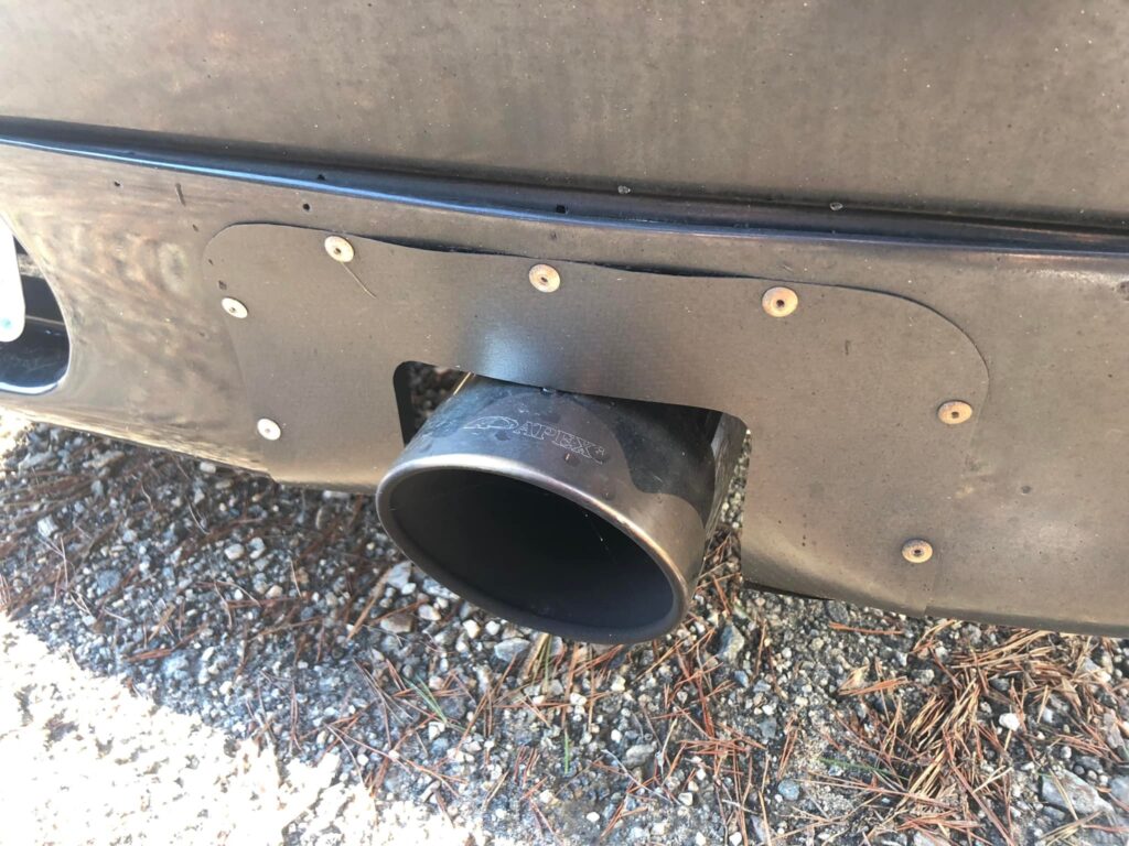
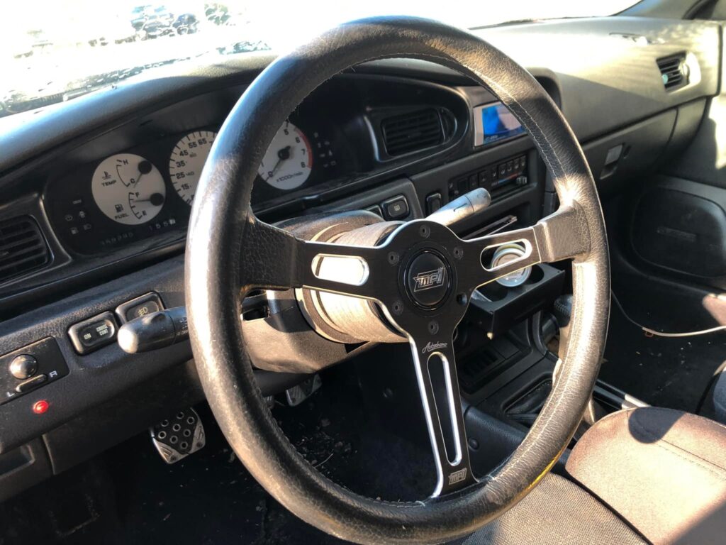
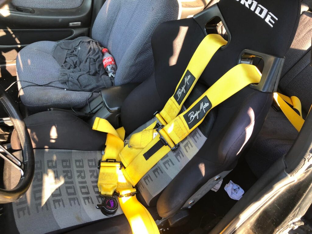
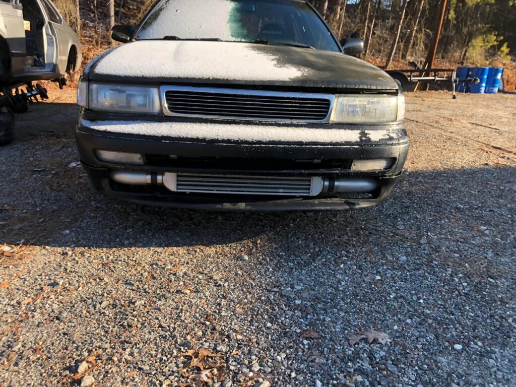
Owner: Chad Sommer
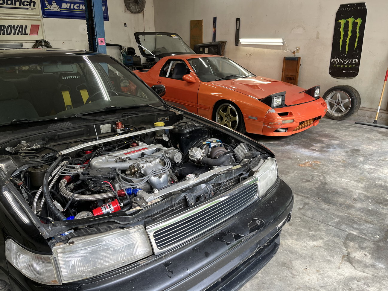
Year: 1989
Model: Maxima
Color: Black
Transmission: 5-Speed Manual
Trim: SE


![]()

Member Credit: choray911
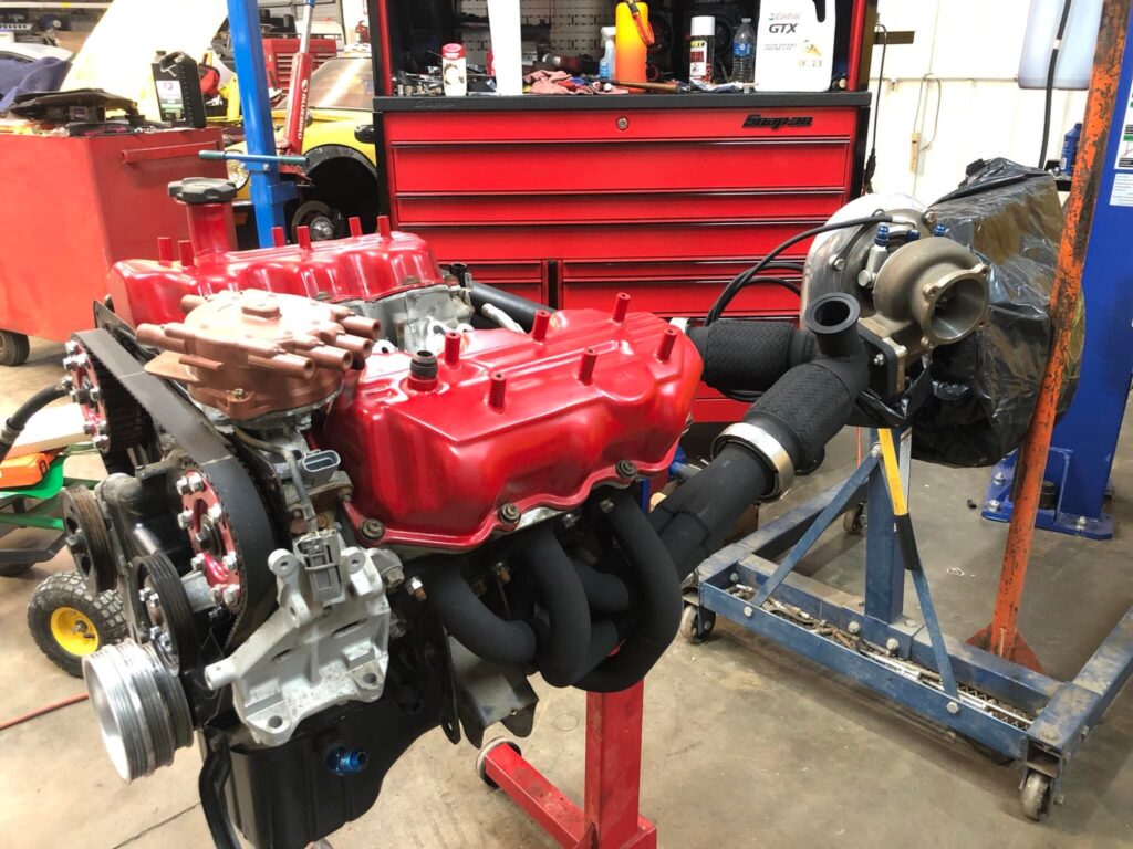
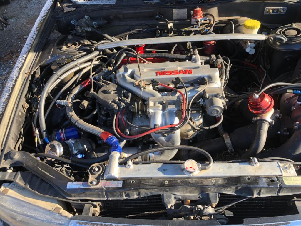
This is a project that has been on my slate for a while, and I’m finally getting around to it. I have seen several people ask what the advantages of stiffer motor mounts are. The answer it simple, the more you reduce the amount the motor moves by rotational force, the more power you put to the pavement, and reduce wheel hop. They do not increase power but allow you to harness the power you already have. The downside is that engine vibration is greatly increased inside the cabin. There are trade-off in every project you take on.
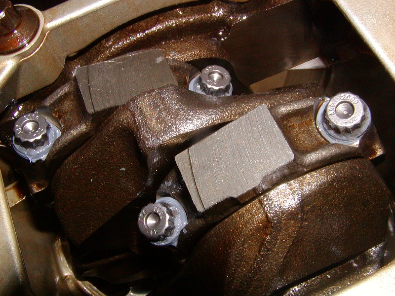
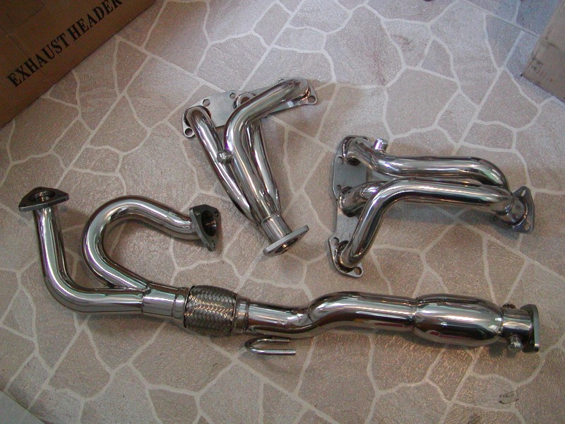
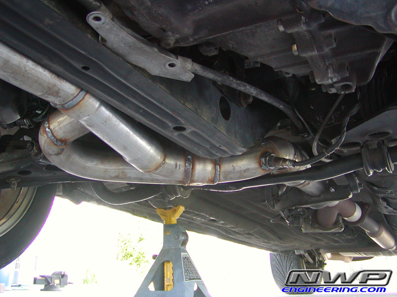
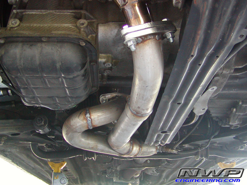
Jack up the car and support with jack stands. Remove the lower engine cradle. This can be done by supporting the weight of the motor with your floor jack to slowly lower it down. The tranny and timing cover mounts will support the motor while the lower support is out of the car. I’ve been turbo’d for 5 years, and I cannot recall if removal of the Y pipe is necessary. Use your own judgment.

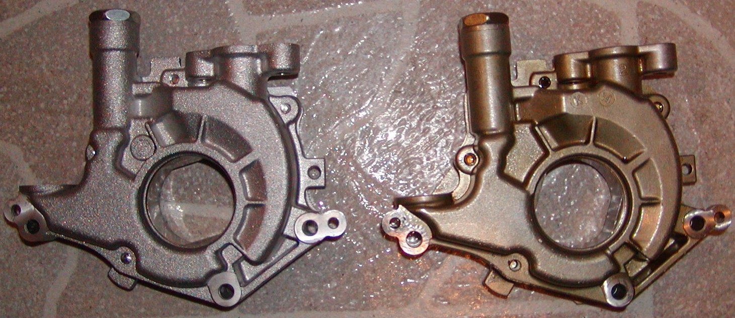
Once the mounts are out of the car, evaluate the condition of your mounts. You will want to remove a lot of the factory material; however, you do not want to change the location of the center bushing. Make sure you have a way to keep it in its factory location. I made sure I had plenty of rubber on both ends to keep it in place during curing.

Remove as much factory material as you feel comfortable with. The more Poly you have in there the stronger it will be. To do so, I used an electric drill and several sized drill bits, and a set of needle-nosed pliers. There is considerable metal reinforcement on the inside of the mount, so don’t be too afraid to explore. Just remember to keep the center bushing centered.


Cleanliness is next to Godliness! Get a bucket of hot soapy water and scrub away. The cleaner the inside of the mounts are the better the poly will stick to it. Depending on the funkiness, you might want to hit them with some degreaser first. Dawn dishwashing detergent works wonders. If your mom won’t get too upset, put them in the toaster oven at 200 degrees to for an hour or so, to make sure they are good and dry.

Seal one side of the motor mount. Trace out the outer boundary of the mount on cardboard and cut it out. Lay the mount on its side and center the circle cardboard piece on the center bushing. Lightly tap the center of the cardboard to make an impression of the center bushing. Cut out the center impression a little small, and then force it onto the center bushing. This will stop the resin from pouring out the bottom. Cover the cardboard piece with aluminum foil, and pull it tight without tearing. Spray some sort of release agent (PAM, Olive oil, WD-40) only on the side that will make contact with the motor mount. Tape it into place using masking tape. Masking tape will not leave a residue like duct tape, but this is your project. Tape the ring securely to the mount. The more tape the better. There will be leaks that show up; this will just keep them at a minimum. Don’t forget to tape around the center hole really well. The resin pours in like warm molasses, and if it has a place to go, it WILL LEAK OUT. Then you have to start over.


The Pour. The polyresin I used was Devcon, Flexane 94. It dries the hardest of their line; however, they do have Flexane 60 that is more flexable. It can be picked up at any industrial supply store, like Granger, for around $36. The kit comes with the resin, curing agent, plastic cup to mix it in, and a stir stick. One “kit” will build two mounts with some leftover if you remove a considerable amount of material from the factory mount. Place the mounts on their sides, and make them level. Rolls of duct tape or masking tape work. Combine the resin and activator according to the enclosed directions and stir for a good 7 to 10 minutes. The mixture has a work time of a good ten to fifteen minutes depending on temp and humidity. The warmer it is the faster it cures. You only have one shot at this, so make sure the mounts are ready to be filled. Pour slowly and try to keep from developing bubbles in the mount. Fill one-half full; fill the next one-half full, and then top off the first.
This gives the resin a chance to seep into all the nooks and crannies and allowing the air to escape. If small leaks appear, don’t freak out. The resin will thicken up and stop leaking. If a big leak shows up, get creative, you didn’t follow the directions.


The Cure. The mixture will harden so that it can be handled within 30 to 45 minutes. To speed up this time, place them under a heat lamp. I have a torch lamp in my living room that has 3 adjustable lights that work perfectly. Remove the cardboard end and foil. They are hard in 24 hours and reach full stiffness within 7 days. If this is a two-day project then you can put them in the oven again at 200 degrees for 24 hours to speed up the cure.

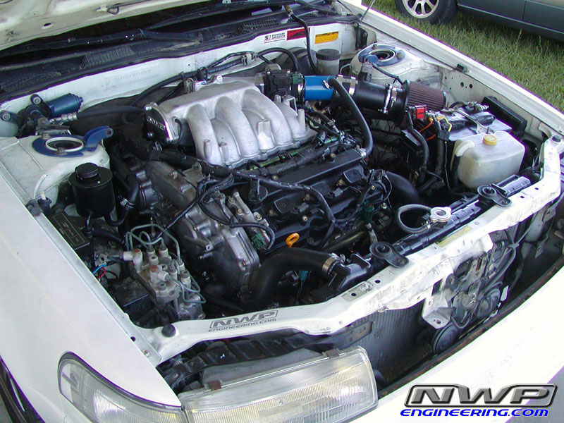
Reinstall.
![]()


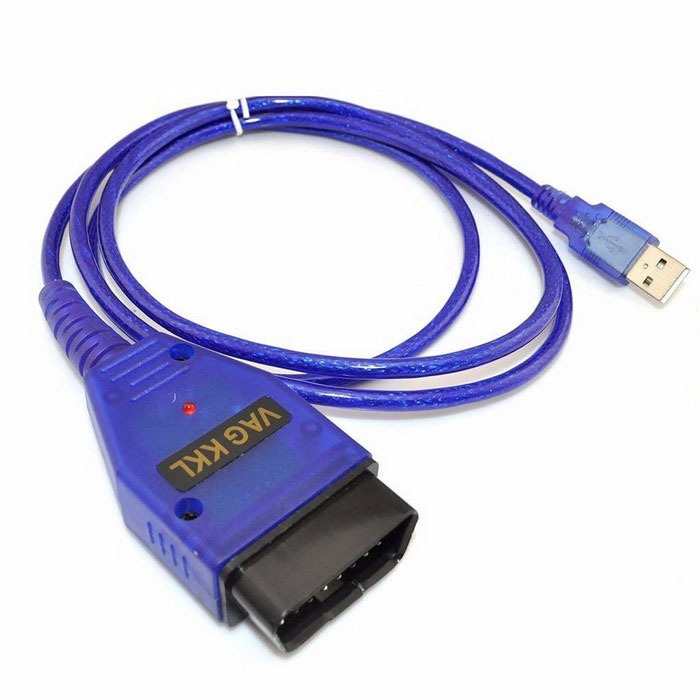
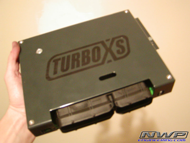
If you are DIY person and love working on your Nissan Maxima, then this tool is a MUST HAVE! When you go to the Nissan dealer, the person working on your car typically uses a tool called a Nissan Consult. The Nissan Consult that the dealer uses costs thousand of dollars and is only available to dealers. By using the Nissan DataScan software, a laptop and a generic VAG COM OBDII adapter you can achieve just about the same level of on-board diagnosis that $5,000 Nissan Consult provides. This software allows you to:
The software itself costs $55.00 and generic cable costs around $7.00-$8.00.
Software License Purchase Link: Nissan DataScan II
Software Download Links:
OBD2 Cable Order Links:
You can find the cables on eBay between $12.00-$20.00 shipped. It ranges based on location and shipping. Search for the following keywords on eBay and you will find it: “KKL 409.1 VAG-COM OBD2 USB Cable”
Below are all the functions it provides:
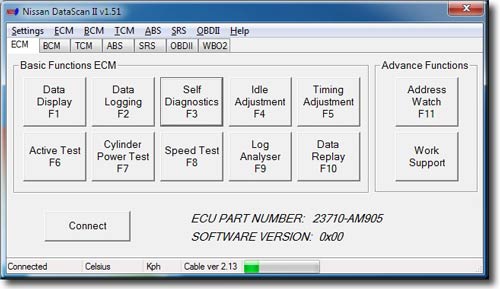
This is the main window of the NDSII software which shows the ECM Nissan Identification part number. Basic and Advance Functions can be selected by clicking on the buttons, using the shortcut keys (F1 – F11) or using the Menu bar. Most functions except Data Replay and Log Analyser are disabled until communication with the ECU is successfully established.
Progress bar at the bottom indicates communication between the ECU and PC. If the bar is not moving there is no data being received from the ECU.


This window is used to assign parameters to be displayed by the Data Display function. Only parameters that are supported by the currently connected ECU are available for selection. Gauges are counted from left to right, top to bottom. Multiple gauges can monitor the same parameter.
Data Logging ECM

Selected parameters can be logged to a file. This function can also be accessed from the Data Display window. The data log file can be analysed using the Data Replay or Log Analyser functions.

Self Diagnostics function allows users to read and reset engine ECU error codes.
Idle Adjustment

Idle Adjustment function allows users to adjust the base idle RPM. The setting is saved to the ECU and it does not reset with engine restart.
Timing Adjustment

Timing Adjustment function allows users to adjust the base ignition timing. The setting is saved to the ECU and it does not reset with engine restart.
Active Test ECM

Active Test allows users to temporary modify some of the engine parameters for testing purposes. They return to their original values when a function is stopped, PC disconnected or engine restarted.
Note: It is possible to damage the engine if the A/F Base % functions is used to excessively modify fuel delivery. Likewise the engine may overheat if the Engine Temperature is set to low for a long period of time. Do not use those functions if you are not sure how they will effect your engine.
Work Support

Work Support functions allow users to perform some of the advance service procedures. Those procedures may need to be performed after replacement parts are installed.
Clear Self Learn – clears the A/F Base SL map learned by the ECU.
Idle Air Volume Learn – is an operation to learn the fully closed position of the throttle valve.
Program Immobiliser Key – allows to register the Nissan transponder keys with the Immobiliser Note: The immobiliser security PIN CODE needs to be known. Initially all registered keys will be erased and all keys will need to be reregistered.
Cylinder Power Test
Cylinder Power Test function can be used to identify cylinder that is under performing. This function allows shutting down individual cylinders. If all of the cylinders are producing the same amount of power the engine RPMs will drop exactly the same amount on each cylinder that is cancelled.


Log Analyser is used to review log files previously generated by with Data Logging function. Graphs are drawn by selecting boxes next to parameter value. Graph colours match the parameter value colours.
Speed Test
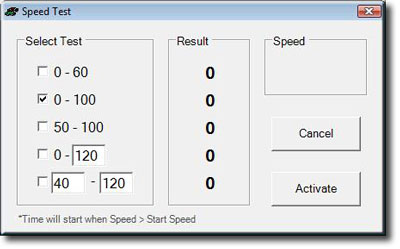
Speed Test is a unique function for measuring car’s acceleration performance. Predefined or user specific tests can be used. Due to the low resolution of Nissan speed sensors, measurements should only be used as a guide and not a true reflection of car’s performance.
Note: This function should not be used while driving on public roads.
Address Watch

Address Watch function is used for monitor specific ECU memory addresses. By monitoring a memory address extra information can be retrieved that is not normally available using Consult II protocol. A knock sensor reading can be obtain using this method if knock sensor memory address is known.
Wideband O2 sensor

Nissan DataScan II also supports wideband Air/Fuel ratio meters from Innovate Motorsports. A second serial port is used to connect to the controller and collect data.
The data from the wideband meter can be displayed or logged in conjunction with other engine parameters using the Data Logging function.
ECU Part Number BCM

The BCM tab shows the BCM Nissan Identification part number. Basic Functions can be selected by clicking on the buttons or using the Menu bar. All functions are disabled until communication with the ECU is successfully established.
Progress bar at the bottom indicates data being send between the ECU and PC. If the bar is not moving there is no data being received from the ECU.
Note: Some vehicles may use K line for diagnostics of engine ECU (ECM) but still use DDL1 line for diagnostics of other control modules. This software does not support diagnostics over the DDL1 line. Some of those models are: X-trail, Maxima, Patrol.
Self Diagnostics BCM

Self Diagnostics function allows users to read and reset BCM error codes.
Active Test BCM

Active Test allows users to temporally activate some of the functions of the BCM. This is usually used to manually test the functionality of the systems controlled by the BCM.
Note: Functions not supported by the BCM are disabled (grayed out).
ECU Part Number TCM

The TCM tab shows the TCM Nissan Identification part number. Basic Functions can be selected by clicking on the buttons or using the Menu bar. Most functions except Data Replay and Log Analyser are disabled until communication with the ECU is successfully established.
Progress bar at the bottom indicates data being send between the ECU and PC. If the bar is not moving there is no data being received from the ECU.
Note: Some vehicles may use K line for diagnostics of engine ECU (ECM) but still use DDL1 line for diagnostics of other control modules. This software does not support diagnostics over the DDL1 line. Some of those models are: X-trail, Maxima, Patrol.
Data Logging TCM
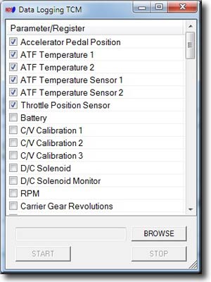
Selected parameters can be logged to a file. This function can also be accessed from the Data Display window so the data can be logged while it is displayed. The data log file can be analysed using the Data Replay or Data Analyser functions.
Self Diagnostics TCM

Self Diagnostics function allows users to read and reset TCM error codes.
ECU Part Number ABS

The ABS tab shows the ABS Nissan Identification part number. Basic Functions can be selected by clicking on the buttons or using the Menu bar. Most functions except Data Replay and Log Analyser are disabled until communication with the ECU is successfully established.
Progress bar at the bottom indicates data being send between the ECU and PC. If the bar is not moving there is no data being received from the ECU.
Note: Some vehicles may use K line for diagnostics of engine ECU (ECM) but still use DDL1 line for diagnostics of other control modules. This software does not support diagnostics over the DDL1 line. Some of those models are: X-trail, Maxima, Patrol.
Data Logging ABS
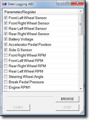
Selected parameters can be logged to a file. This function can also be accessed from the Data Display window so the data can be logged while it is displayed. The data log file can be analysed using the Data Replay or Data Analyser functions.
Self Diagnostics ABS

Self Diagnostics function allows users to read and reset ABS error codes.
Work Support ABS
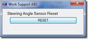
Work Support functions allow users to perform advance service procedures. Those procedures may need to be performed after replacing parts.
Steering Angle Sensor Reset – After removing/installing or replacing VDC/TCS/ABS control unit, steering angle sensor, steering components, suspension components, and tires, or after adjusting wheel alignment, make sure to adjust neutral position of steering angle sensor before running vehicle.
ECU Part Number SRS
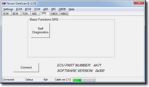
The SRS tab shows the SRS Nissan Identification part number. Basic Functions can be selected by clicking on the buttons or using the Menu bar. All functions are disabled until communication with the ECU is successfully established.
Progress bar at the bottom indicates data being send between the ECU and PC. If the bar is not moving there is no data being received from the ECU.
Note: Some vehicles may use K line for diagnostics of engine ECU (ECM) but still use DDL1 line for diagnostics of other control modules. This software does not support diagnostics over the DDL1 line. Some of those models are: X-trail, Maxima, Patrol.
Self Diagnostics SRS

Self Diagnostics function allows users to read and reset SRS error codes.
Note: Recorded faults are historical and can not be cleared.
Work Support
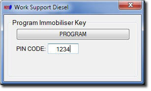
Work Support functions allow users to perform the advance service procedures. Those procedures may need to be performed after replacement parts are installed.
Program Immobiliser Key – allows to register the Nissan transponder keys with the Immobiliser Note: The immobiliser security PIN CODE needs to be known. Initially all registered keys will be erased and all keys will need to be reregistered.
OBDII Self Diagnostics
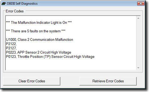
OBDII Self Diagnostics function allows users to read and reset ECU error codes.
OBDII Monitor Status

OBDII Monitor Status shows the current status of various monitoring systems used by the car’s engine management system.
OBDII Log Analyser

Log Analyser is used to review log files previously generated by with Data Logging function. Graphs are drawn by selecting boxes next to parameter value. Graph colours match the parameter value colours.
OBDII Fuel System Satus

OBDII Fuel System Status can be used to check if the car’s fuel system is running in Closed Loop mode.
Fuel systems do not normally refer to injector banks. They are intended to represent completely different fuel systems that can independently enter and exit closed loop fuel. Banks of injectors on a V-engine are generally not independent and share the same closed-loop enablement criteria.
OBDII Data Logging

Selected OBDII parameters can be logged to a file. The data log file can then be analysed using the Log Analyser function.
Due to the slow nature of OBDII protocol it’s recommended to log only the required parameters.
![]()

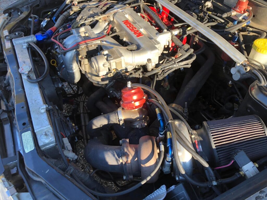
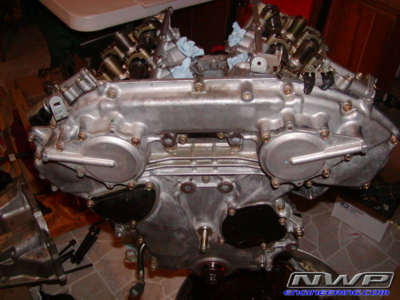
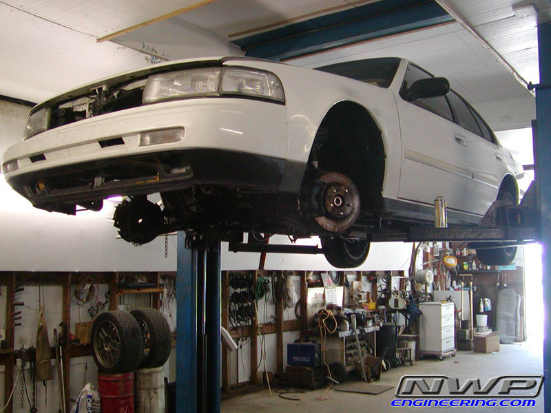
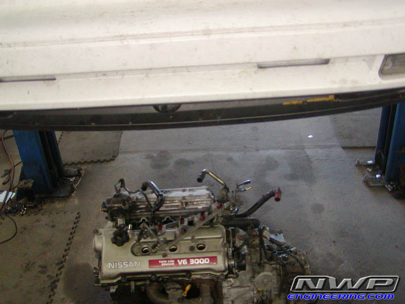
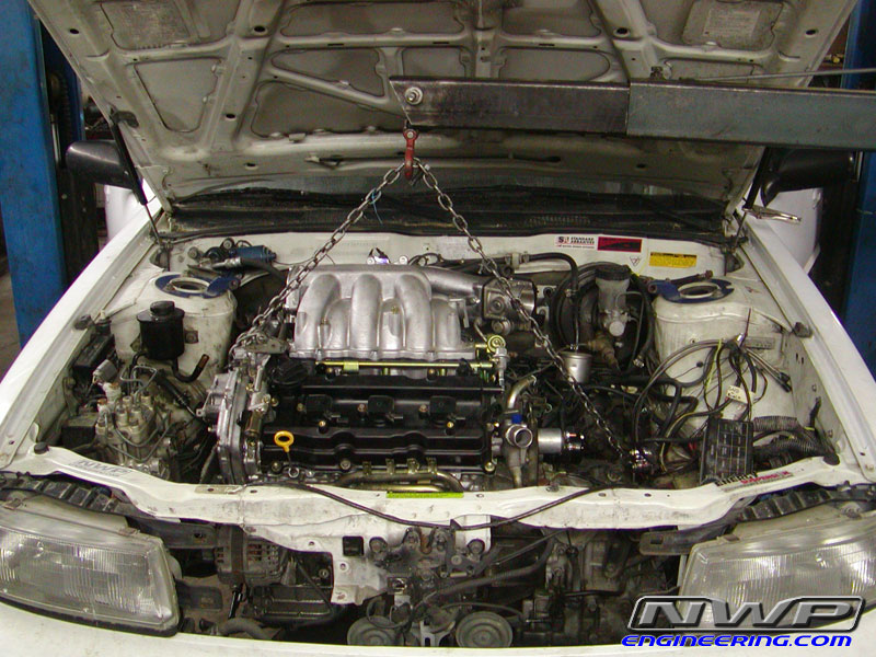
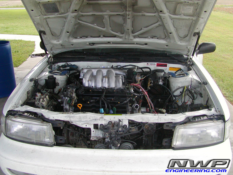
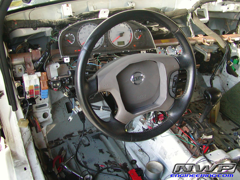
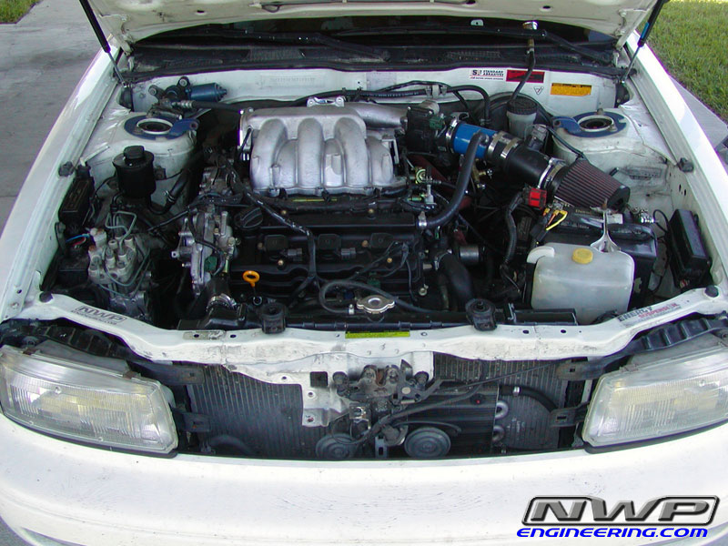
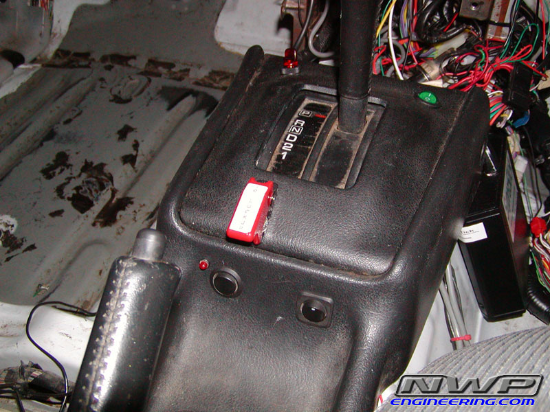
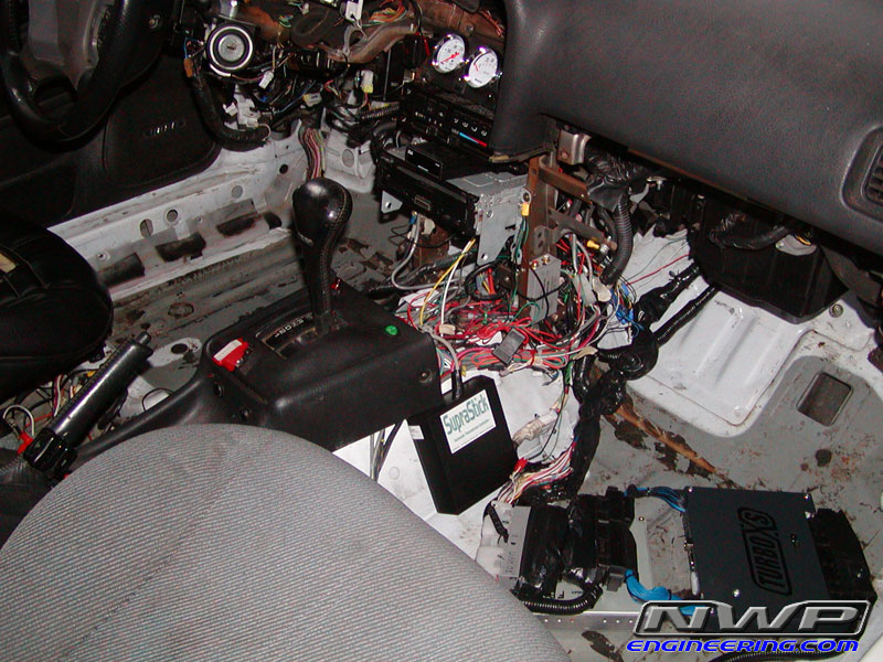
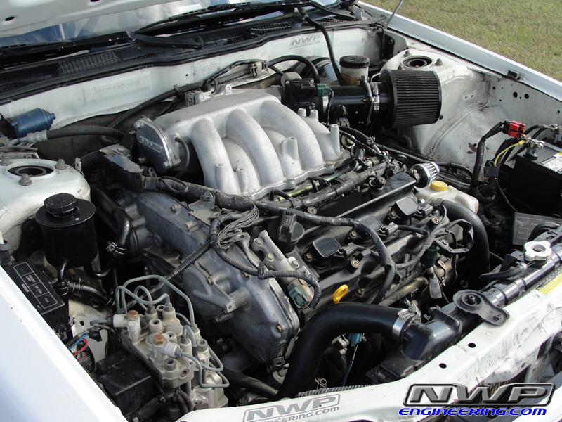
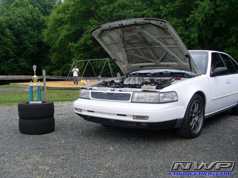
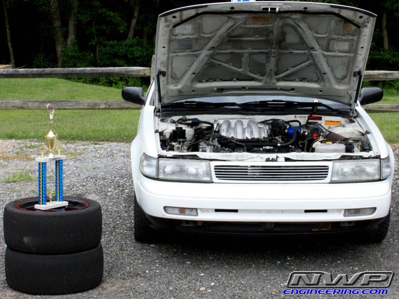
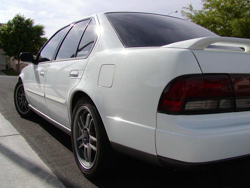
Owner: Aaron Kimball
Year: 1992
Model: Maxima
Color: White
Trim: SE
Engine: VQ35DE
Transmission: 4-Speed Automatic Transmission
Highlights:
![]()
![]()
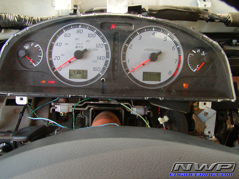
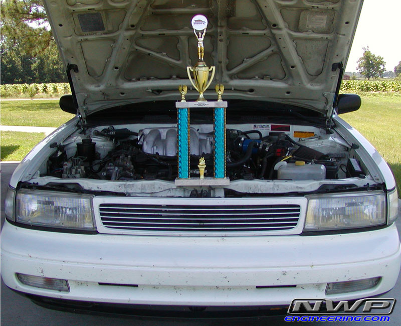


Quick Car Info
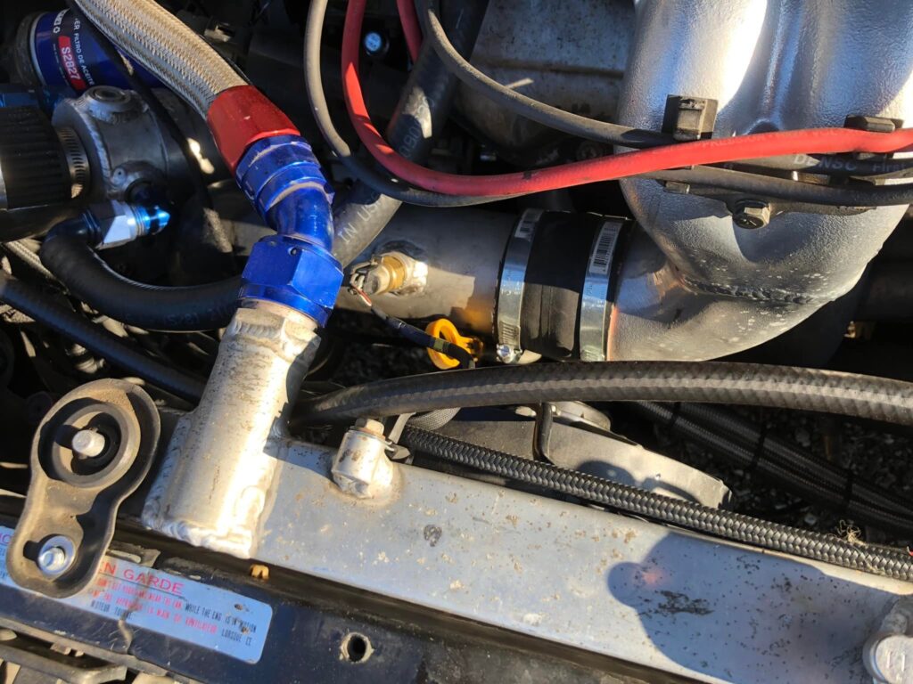
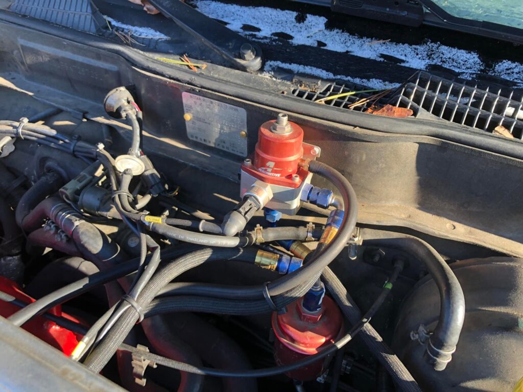
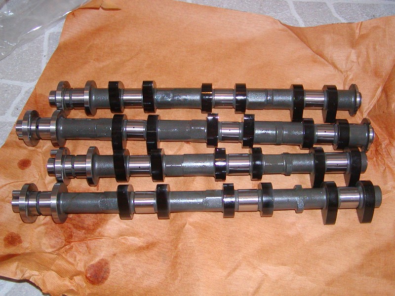
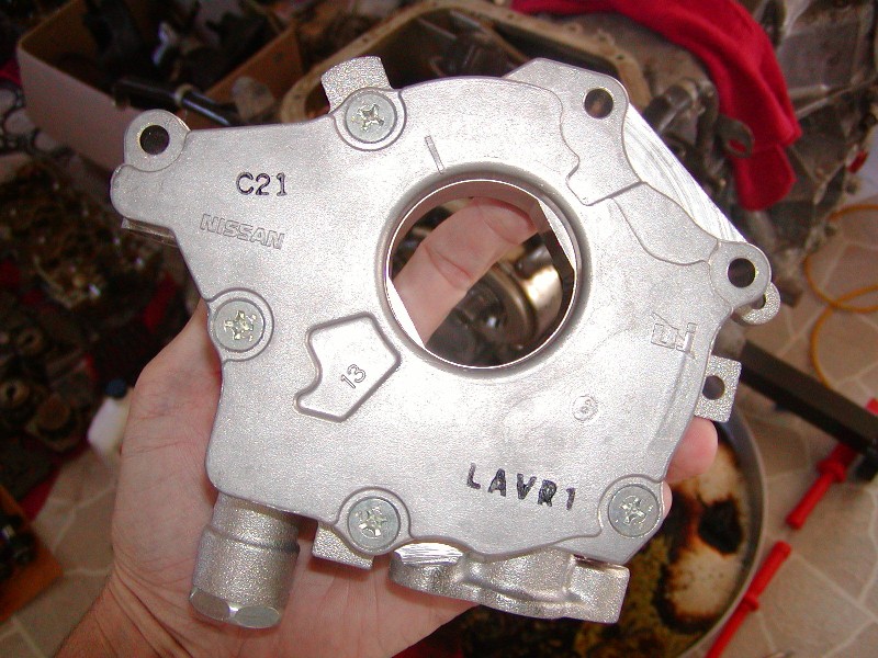
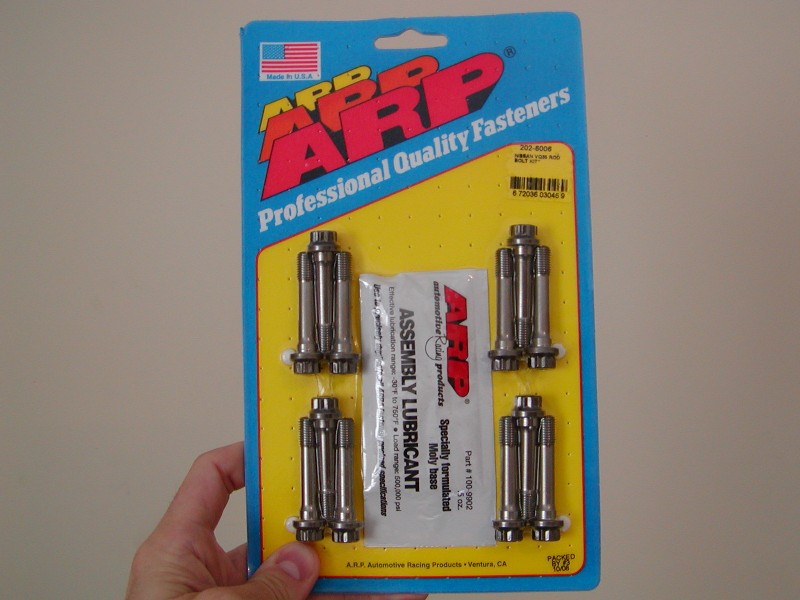
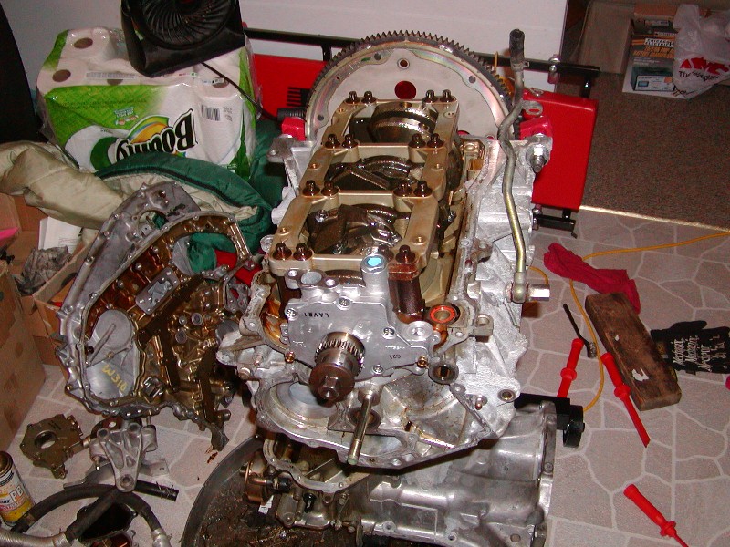
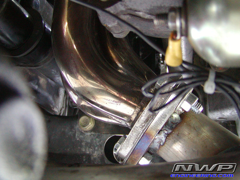
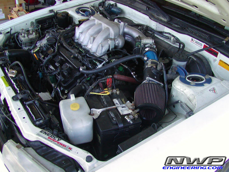
Go Fast Mods and Engine Specs
14×6 OEM Ford Ranger wheels w/ 20x8x14 Mickey Thompson ET Drag Slicks
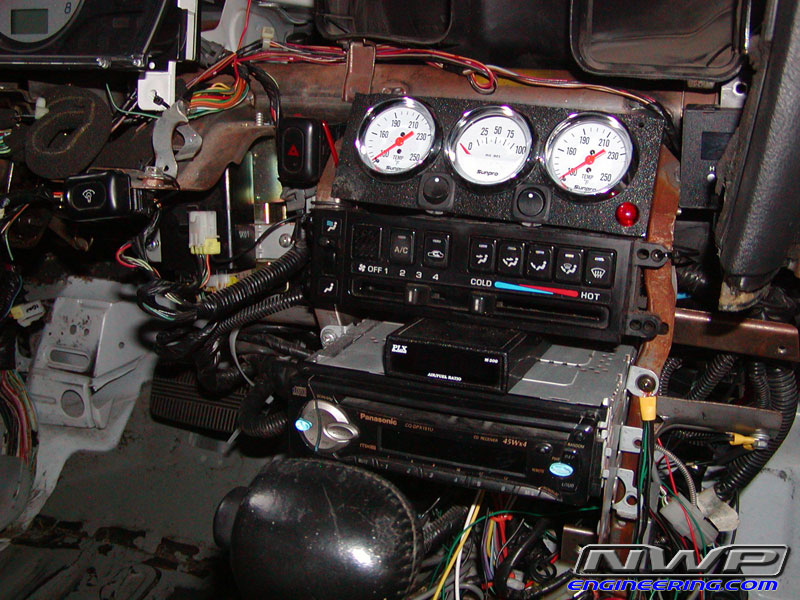
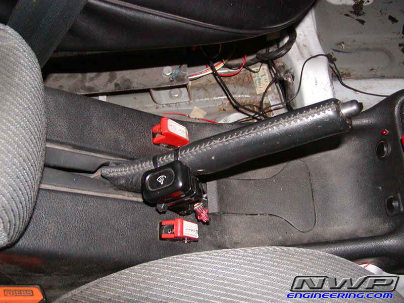
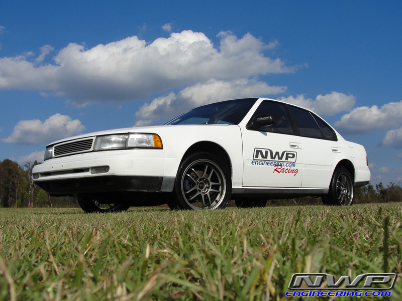
Other Performance Mods
Handling & Braking Mods
Appearance Mods
![]()