Category

my6thgen 04-08

Category

Community Member Credit: BOOTZ

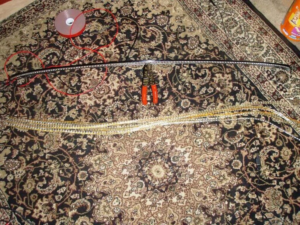
So this was done using a red waterproof 120cm strip from eBay. Make sure you measure to be sure.

Description: 2pcs Red 120cm LED Side-emitting Shine Strips Side Glow Flexible Neon Brake lamp
Order Link: https://www.ebay.com/itm/272474776774
Price: $12.25 (Shipped)

Instructions:

I started out by removing the driver’s side rear window molding. There is one 10mm bolt you have to remove and only visible when you open the trunk.

Once that is removed start prying upwards on the molding starting from the bottom and working your way up. There are about four clips holding it on. Be careful not to put too much pressure on the window or the body of the car. Don’t want to break glass or dent anything.

Once off should look like so….

Then take you led strip and apply two sided tape to it. I used 3m. You want to clean the led strip really well then I heated up the led and the tape before applying it. Did the same on the window. Cleaned it really well and heated it up.

Before applying the led to the window I set the roof spoiler in position and placed a small piece of the led underneath to see where i could place it without getting in the way of mounting the spoiler. Turned out to be maybe 1/2″ from the top of the window.

Also before applying, make sure your wires are running down the driver’s side. That is where the rubber boot is where the wires will run in.

You are then able to run the wires down towards the rubber boot going into the vehicle. I just tucked them under the window. The molding will cover it up anyway.

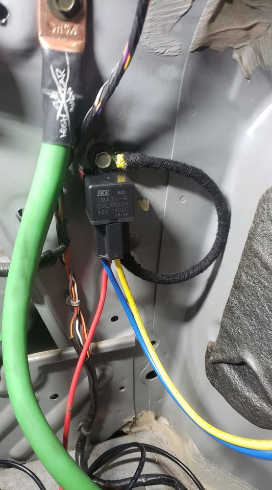
From here you can tap into the existing wires to the factory 3rd brake light (6.5 gens). If you don’t have the factory spoiler with 3rd brake light wires should be the same colors found in harness running towards the front of the vehicle.

If you pull up on the boot you can find your wires there.
12v – Red/Green
Ground – Black

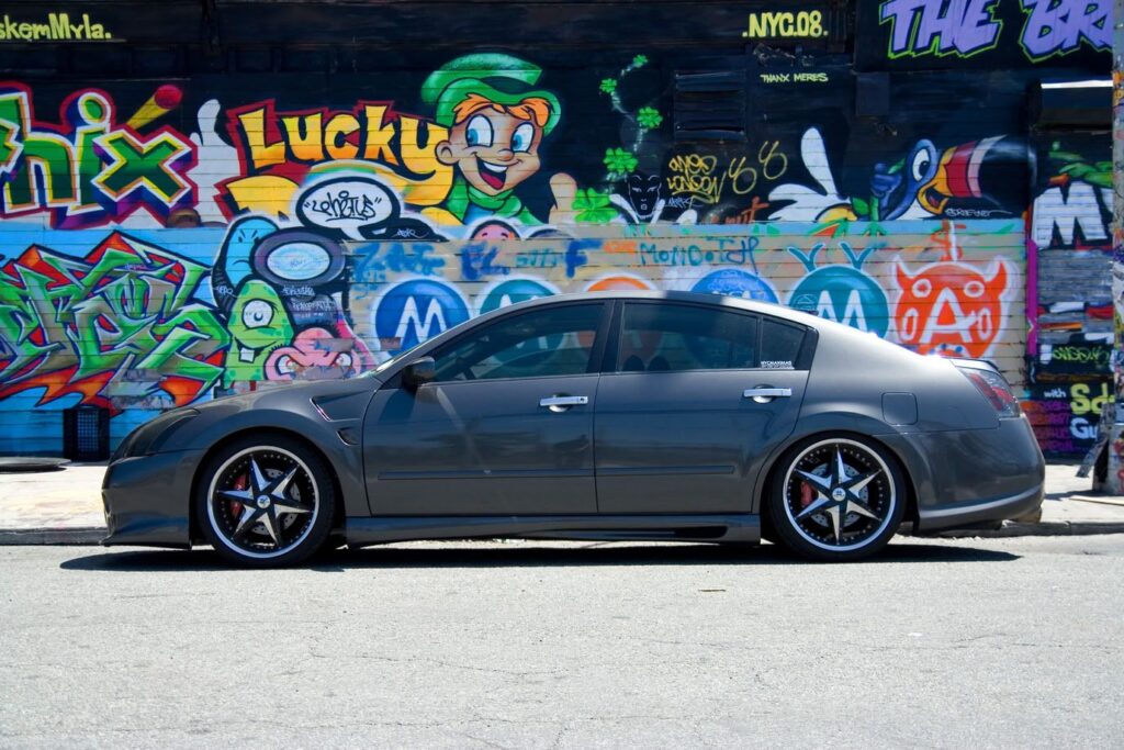
From here you should be able to mount your roof spoiler and reassemble everything.

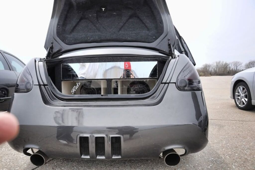
Here you can see they are pretty hidden unless you really look for them.

Night shots…

I also ended up putting a black vinyl overlay on the factory 3rd brake light to make it look like part of the spoiler. You could paint it to match the vehicle’s color if you don’t ever plan on using again.

Additional Reference Photos from DEADBOLT

I 3M taped the strip to the edge of the roof spoiler for it to be more visible.

I cut down the strip to fit exactly the lines of the spoiler and wired an exted + and – wires to it so I can connect it to the interior plug of where the old 3rd brake light use to be.

Test Pics:

Lights off shot:

Video from CHULO

Loading

Community Member Credit: JIME

Not sure if this has been visited before but my Son recently brought it to my attention when we were discussing running a 200 shot of spray. He suggested that I use his nitrous test kit to ensure the fuel pressure remained constant when running a 200 fuel jet. So after a few minutes I soon found out that my 190 Walbro dropped to 30 psi, not good. He then mentioned that a lot pf VW and DSM guys rewired their fuel pump with a higher gauge wire to maintain a higher voltage. I measured the voltage at the pump with the engine running and found it to be just over 12v. I then ran a heavy gauge wire from the battery and conected it to the pump wire at the pump, the voltage went up to almost 14 and the fuel pressure went up by almost 10 psi.

So it was off to the store to buy some heavier wire. I decided on 10 gauge rather than something heavier because of the difficulty soldering heavier wire as well as routing. The stock wire at the pump is 14 gauge but if you strip the wire back a couple of feet you will find it increases to 12 gauge.

The easiest way is to run the heavier gauge wire directly from the battery with a fuse and use a relay to connect to the pump. Use the original pump supply wire to fire the relay and use the larger wire on the N.O contacts to run the pump.

Auto Performance has a couple of charts comparing 12v vs 13.8v and their corresponding flow rates and current draw.. Pretty impressive comparison. eg For my pump at 50 psi the flow rate increases from 36 to 46 gal/hr while the current draw remains the same.

I would suggest an adjustable FPR to compensate for the increased pressure.

A 255 pump was installed because even with the increased voltage the 190 pump would not handle a 200 shot. After installing the new pump my pressure increased to over 80 psi and took a lot of adjustment to bring it back into the 50 psi range.

Loading

Owner: Luis A.

Year: 2005
Model: Maxima
Current Color:Gun Metallic
Transmission: 5-Speed Automatic
Trim: SE Elite

Video

Mod List:

  • AEM CAI
  • Kinetix Upper Intake Manifold
  • Port and Polished Lower Manifold
  • +2 Degrees Timing Advance
  • Greddy SP2 Catback Exhaust System
  • Greddy Ultimate E-manage
  • Cattman Y-Pipe
  • Cattman Headers
  • NWP Phenolic Spacers
  • STILLEN UDR Racing Pulley
  • NISMO White Decal on Fuse Box (15hp Extra)
  • Tein Basics Coilovers
  • Racinline End Links F+R
  • Nismo-S (Altima SE-R) Sway Bar Front/Rear
  • Stillen Front Strut Bar
  • Wilwood BBK All Around
  • Hipnotic Wheels 20×8.5 Chrome Rims w/ Black Inserts
  • Toyos High Performance
  • NISMO Chrome Tire Valves
  • Momo Chrome/Leather Shifknob
  • Momo Racing Aluminum Pedals
  • DVD Player
  • Headrest Monitors
  • A/V Converter to Allow Movie Playing on GPS Screen
  • 2 LCD Screens Located in Trunk
  • 3 MATT Amps with Blue LEDs
  • Kinetix Battery
  • 2 2,000 Watts MATTs Subs
  • Strobe Lights Inside Subwoofer Box
  • Sarona Full Body Kit
  • Blue LEDs Running Lights and Wheel Well Lights
  • 3000k Fog Lights
  • Strobe Lights
    EZK CF Hood
  • DEPO Chrome Red LED Tail Lights Lightly Tinted
  • Vertical Doors Lambo Door Kit
  • Chrome Door Handles
  • SE Mesh Grill with JDM Positioned NISMO Logo
  • Tinted Headlights
  • White LED Back-Up Lights

Loading

Community Member Credit: Sparky

This 2005 Nissan Maxima came in with the complaint that the tail lights do not work and the fuse blows. The tail light fuse is located in the underhood fuse box on the passenger side of the vehicle. The black plastic trim panel that runs from the firewall to the headlight assembly has to be removed. There are several push pin retainers that hold it in place.

With the trim panel removed grab the fuse box cover and pull it up and off of the fuse box. Note the position of the tail light fuse on the fuse box legend. Be careful around the fuse box and use a gentle hand. There is a processor built into the intelligent fuse box assembly.

Locate the fuse in the fuse box and test both sides of the fuse. This one had power on one leg but not on the other. I replaced the fuse and the park/tail lights started working again. Normal inspections of the bulbs and related wiring found nothing. I started bouncing the body around to see if the fuse would blow. Nothing. I started opening and closing the doors firmly and the fuse blew. Replaced the fuse again and the lights stayed on.

While sitting in the car contemplating what to check next, I noticed that the dome light switch in the overhead console was not sitting properly. A gentle wiggle and the fuse blew. I knew this because the dash illumination lights changed in intensity. A little more wiggling and the switch fell apart.

I found it strange that there would be a tail light circuit attached to the dome light switch and I could find no reference to this in the wiring diagrams.

Once the leading edge fasteners were free the two metal clips at the rear of the assembly were easy to remove.

The dome light switch unplugs from the back of the assembly. The switch and harness are then removed from the front of the light assembly. I called my Nissan dealership to find out that the switch is not sold separately. The cost of the assembly is $350 and only four in the country.

I did some testing and found that if I connected the white wire to the orange wire the dome light would work as if the switch was placed to the auto/door position.

A couple of snips. A splicing connector, some heat shrink tubing and the dome light works as most people expect anyway. Open the door and it comes on. Close the door and it turns off. Slight delay since it is a Nissan design. They prefer their dome lights to fade out gradually.

So if you have a hard to find short in the tail light circuit be sure to check this switch out. If you also do not want to spend $350 on a new light assembly but want the dome light to work, just connect the orange and white wires together as I did. I would strongly recommend checking the wire locations and electrical circuits yourself. Sometimes manufacturers will change the wire color codes for internal wiring and yours may or may not match this one.

The park lights now work without the fuse blowing and the dome light works as the customer requested.

Loading

Member Credit: choray911

This is a project that has been on my slate for a while, and I’m finally getting around to it. I have seen several people ask what the advantages of stiffer motor mounts are. The answer it simple, the more you reduce the amount the motor moves by rotational force, the more power you put to the pavement, and reduce wheel hop. They do not increase power but allow you to harness the power you already have. The downside is that engine vibration is greatly increased inside the cabin. There are trade-off in every project you take on.

Step 1

Jack up the car and support with jack stands. Remove the lower engine cradle. This can be done by supporting the weight of the motor with your floor jack to slowly lower it down. The tranny and timing cover mounts will support the motor while the lower support is out of the car. I’ve been turbo’d for 5 years, and I cannot recall if removal of the Y pipe is necessary. Use your own judgment.

Step 2

Once the mounts are out of the car, evaluate the condition of your mounts. You will want to remove a lot of the factory material; however, you do not want to change the location of the center bushing. Make sure you have a way to keep it in its factory location. I made sure I had plenty of rubber on both ends to keep it in place during curing.

Step 3

Remove as much factory material as you feel comfortable with. The more Poly you have in there the stronger it will be. To do so, I used an electric drill and several sized drill bits, and a set of needle-nosed pliers. There is considerable metal reinforcement on the inside of the mount, so don’t be too afraid to explore. Just remember to keep the center bushing centered.

Step 4

Cleanliness is next to Godliness! Get a bucket of hot soapy water and scrub away. The cleaner the inside of the mounts are the better the poly will stick to it. Depending on the funkiness, you might want to hit them with some degreaser first. Dawn dishwashing detergent works wonders. If your mom won’t get too upset, put them in the toaster oven at 200 degrees to for an hour or so, to make sure they are good and dry.

Step 5

Seal one side of the motor mount. Trace out the outer boundary of the mount on cardboard and cut it out. Lay the mount on its side and center the circle cardboard piece on the center bushing. Lightly tap the center of the cardboard to make an impression of the center bushing. Cut out the center impression a little small, and then force it onto the center bushing. This will stop the resin from pouring out the bottom. Cover the cardboard piece with aluminum foil, and pull it tight without tearing. Spray some sort of release agent (PAM, Olive oil, WD-40) only on the side that will make contact with the motor mount. Tape it into place using masking tape. Masking tape will not leave a residue like duct tape, but this is your project. Tape the ring securely to the mount. The more tape the better. There will be leaks that show up; this will just keep them at a minimum. Don’t forget to tape around the center hole really well. The resin pours in like warm molasses, and if it has a place to go, it WILL LEAK OUT. Then you have to start over.

Step 6

The Pour. The polyresin I used was Devcon, Flexane 94. It dries the hardest of their line; however, they do have Flexane 60 that is more flexable. It can be picked up at any industrial supply store, like Granger, for around $36. The kit comes with the resin, curing agent, plastic cup to mix it in, and a stir stick. One “kit” will build two mounts with some leftover if you remove a considerable amount of material from the factory mount. Place the mounts on their sides, and make them level. Rolls of duct tape or masking tape work. Combine the resin and activator according to the enclosed directions and stir for a good 7 to 10 minutes. The mixture has a work time of a good ten to fifteen minutes depending on temp and humidity. The warmer it is the faster it cures. You only have one shot at this, so make sure the mounts are ready to be filled. Pour slowly and try to keep from developing bubbles in the mount. Fill one-half full; fill the next one-half full, and then top off the first.

This gives the resin a chance to seep into all the nooks and crannies and allowing the air to escape. If small leaks appear, don’t freak out. The resin will thicken up and stop leaking. If a big leak shows up, get creative, you didn’t follow the directions.

Step 7

The Cure. The mixture will harden so that it can be handled within 30 to 45 minutes. To speed up this time, place them under a heat lamp. I have a torch lamp in my living room that has 3 adjustable lights that work perfectly. Remove the cardboard end and foil. They are hard in 24 hours and reach full stiffness within 7 days. If this is a two-day project then you can put them in the oven again at 200 degrees for 24 hours to speed up the cure.

Step 8

Reinstall.

Loading

P0403 is a very common trouble code. It is a generic code, which means that it has the same meaning for the Nissan Maxima as it would any other vehicle. It affects the EGR (Exhaust Gas Recirculation System and technically means:

P0403: EGR→ Circuit Malfunction

A circuit malfunction implies that there is a wiring problem coming to or from the EGR system. That does not rule out the EGR solenoid itself. We’ll go into the most common symptoms and causes of P403 directly below.

As far as the average do it yourselfer being able to diagnose the cause of this code, it can be tricky since a good vehicle scanner and Ohm-meter can make the job a heck of a lot easier.

P0403 Symptoms: Nissan Maxima

Most of the time, there will be no noticeable symptoms accompanied with P0403, with the exception of the service engine soon light itself.

While not typical for any other symptoms to show with the P0403, it is possible that the Maxima will misfire if the EGR system is stuck open.

P0403 Causes

The issues that are going to cause P0403 are going to have to do with the EGR solenoid, or the wiring going to or from it. While it is possible for something else to cause P0403, these are far and away the most likely reasons for the code to populate

Bad EGR Solenoid

There’s going to be two issues that would cause the EGR solenoid not to operate, the solenoid itself, and the wiring going to it.

The EGR solenoid itself is often the cause of P0403. It can be checked with a good OBDII scanner and Ohm meter.

With the scanner, you’d want to command the EGR solenoid to operate. With the ohm meter hooked up, you should see movement on the gauge. If it’s not getting a signal, move on to the section directly below.

This video below is a great resource that’ll help you through the process of testing different EGR types.

Loading