At the bottom of the glove box, there are two black tabs that hold the bottom in place. remove these two tabs.
After remove the tabs, there will be 5-6 screws holding the frame of the glove box in. Remove the screws.
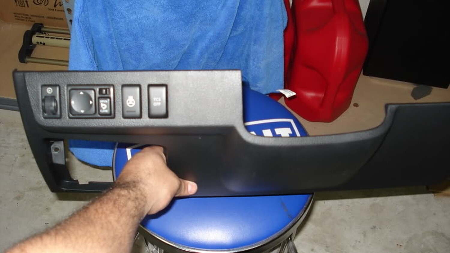
glovebox hanging, the frame is taken off
Gglovebox taken off, frame is off. If you are doing this, checking your in-cabin air filter is a good idea.
And there she is! the ECU, i mean. it is held inside that gold-looking bracket and you can see the connectors from below.
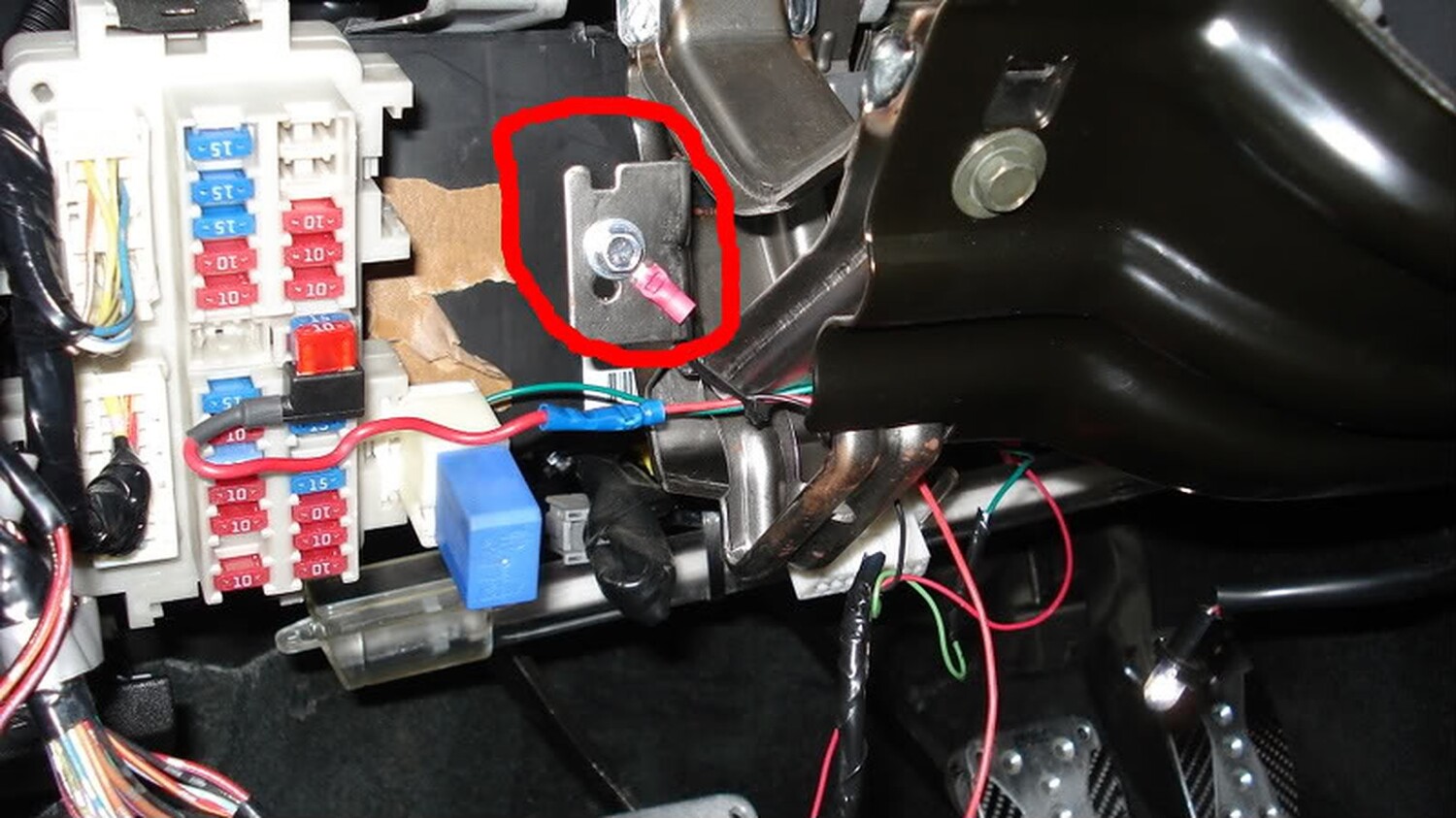
After completing the instructions in the picture, you’re ECU is officially disconnected from the car.
I know back years ago, Jet Performance would mod the ECU for you to make the car faster by mailing it out to them. Technosqaure does or did the same thing. when my friend use to own a 6thgen max, he shipped out his ECU to Jet Performance, and with an intake and a flashed ECU, he beat me by 2 car lengths. my car was in stock form back then. pretty interesting but if you any questions just ask!!
I finally finished installing my last mod. For a while I’ve been searching for a shift light indicator, but nothing as big as a Monster Tach or anything that would make the car look ricey. My idea of a shift light was something that would be small and inconspicuous.
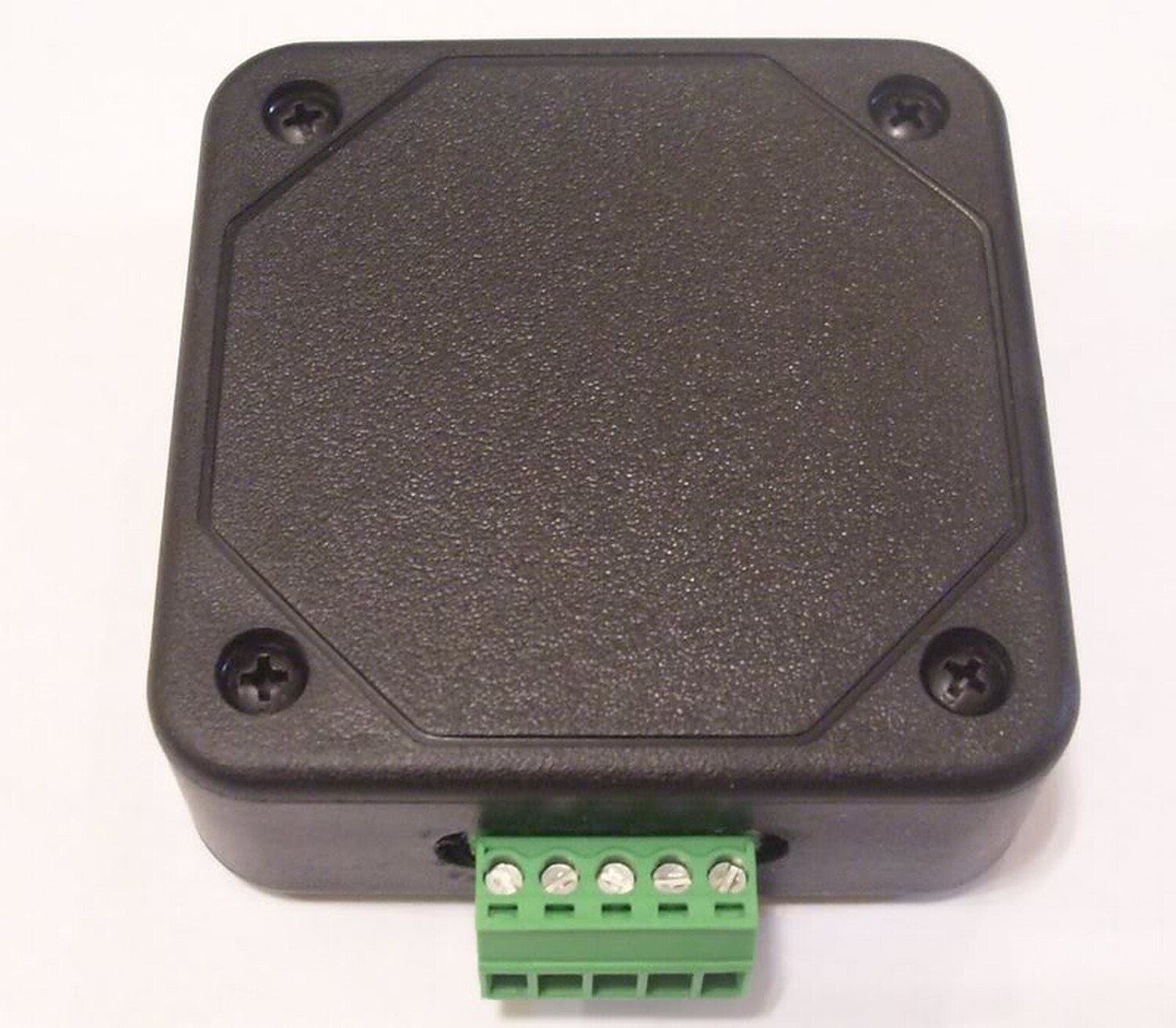
I came across a shift light module from Raptor Performance that allows you to connect a single L.E.D or more. The module is small and can be hidden under the dash and the L.E.D or L.E.D’s can be mounted anywhere in the car. With this module you can have a shift light that is not noticeable and does not take up any space or block your view like a monster tach.
Here are the instructions on how to install the shift light. The total install time was 1 hour and quite simple.
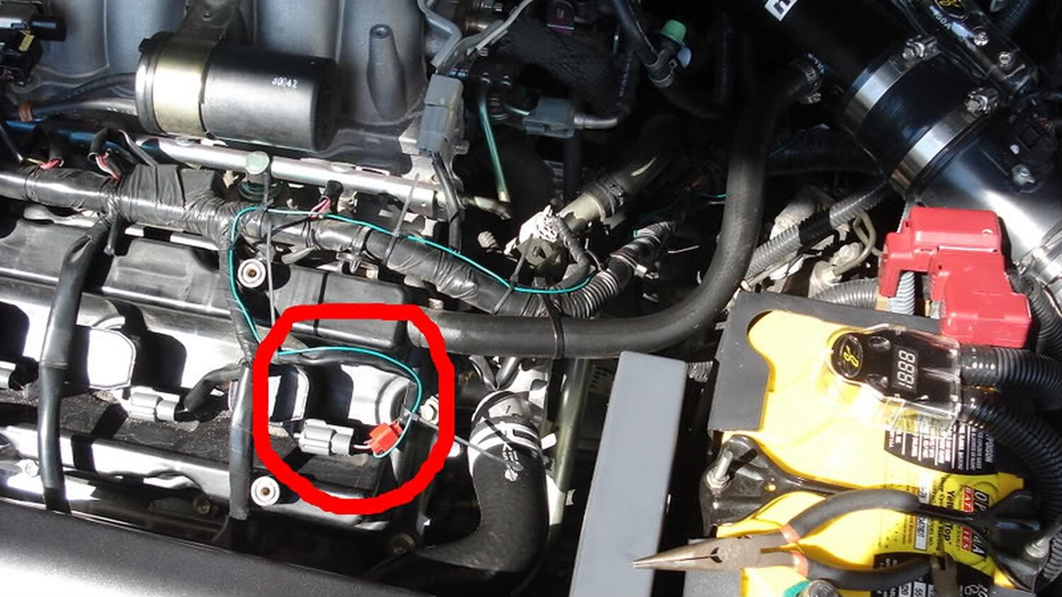
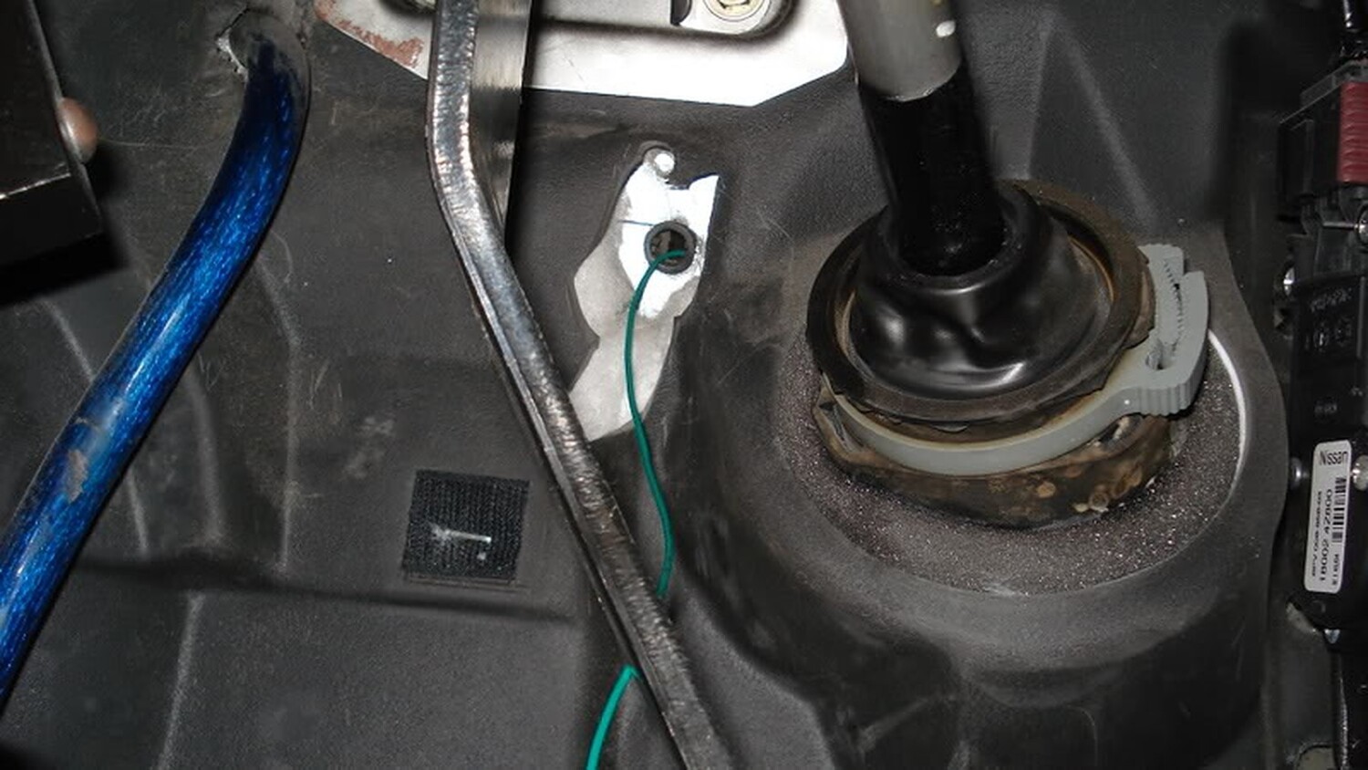
The green wire connects to the tach signal. In our cars this can be found at any ignition coil. Each coil has three wires running to them. Each coil has a red and black wire and the third wire is of a solid color with a stripe. Below is the color configuration for each coil
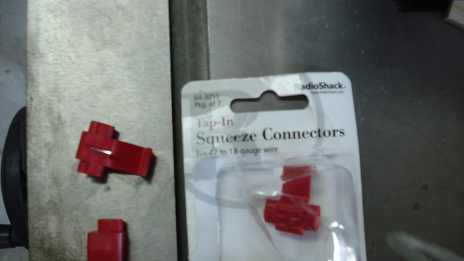
I tapped the Grey/Red wire with a 22 AWG wire tap and ran a 22 AWG wire into the cabin.
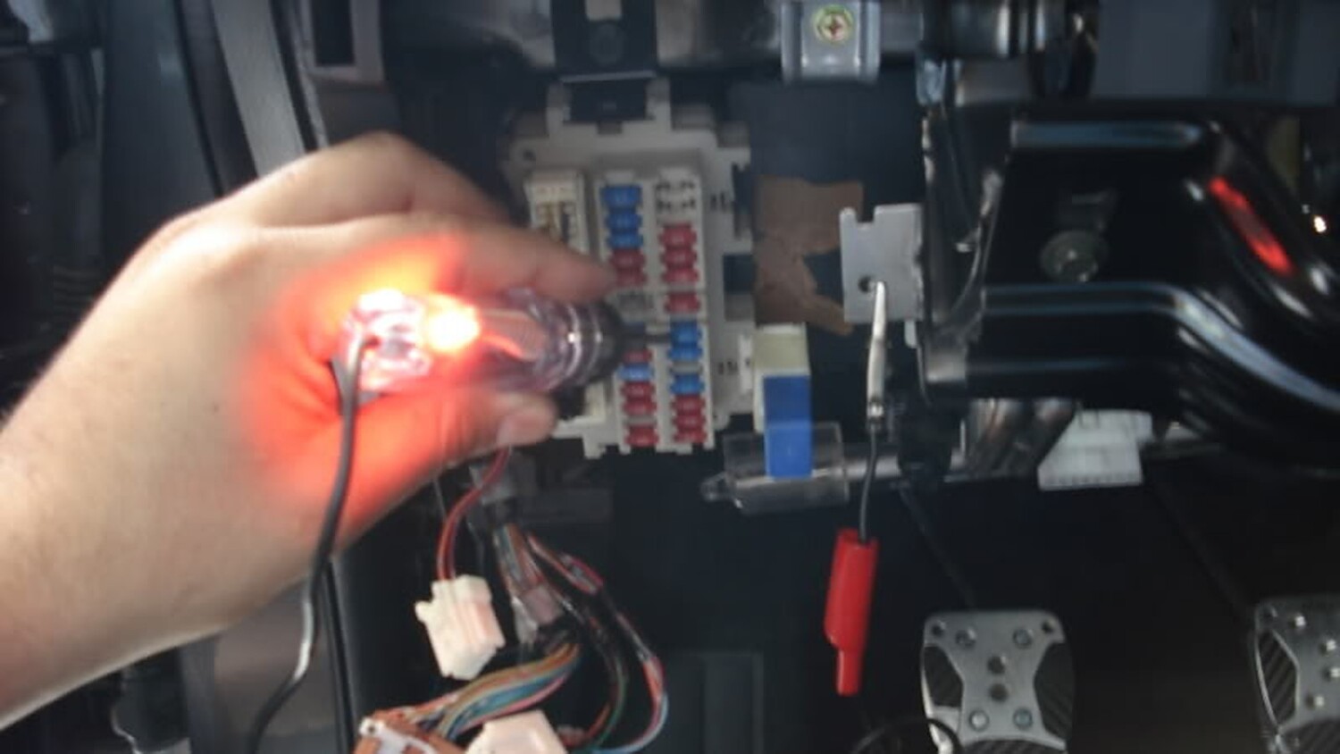
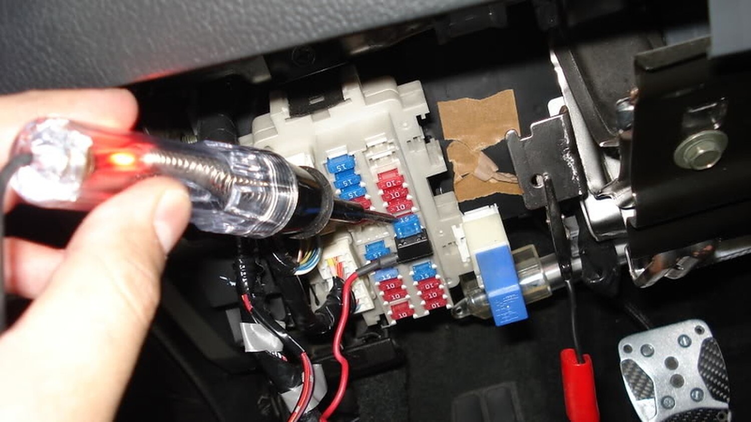
Once I finish running the other end of the wire through the firewall, the next step was to find a 12 volt source and ground. For my 12 volt source I choose the fuse for the rear power sockets
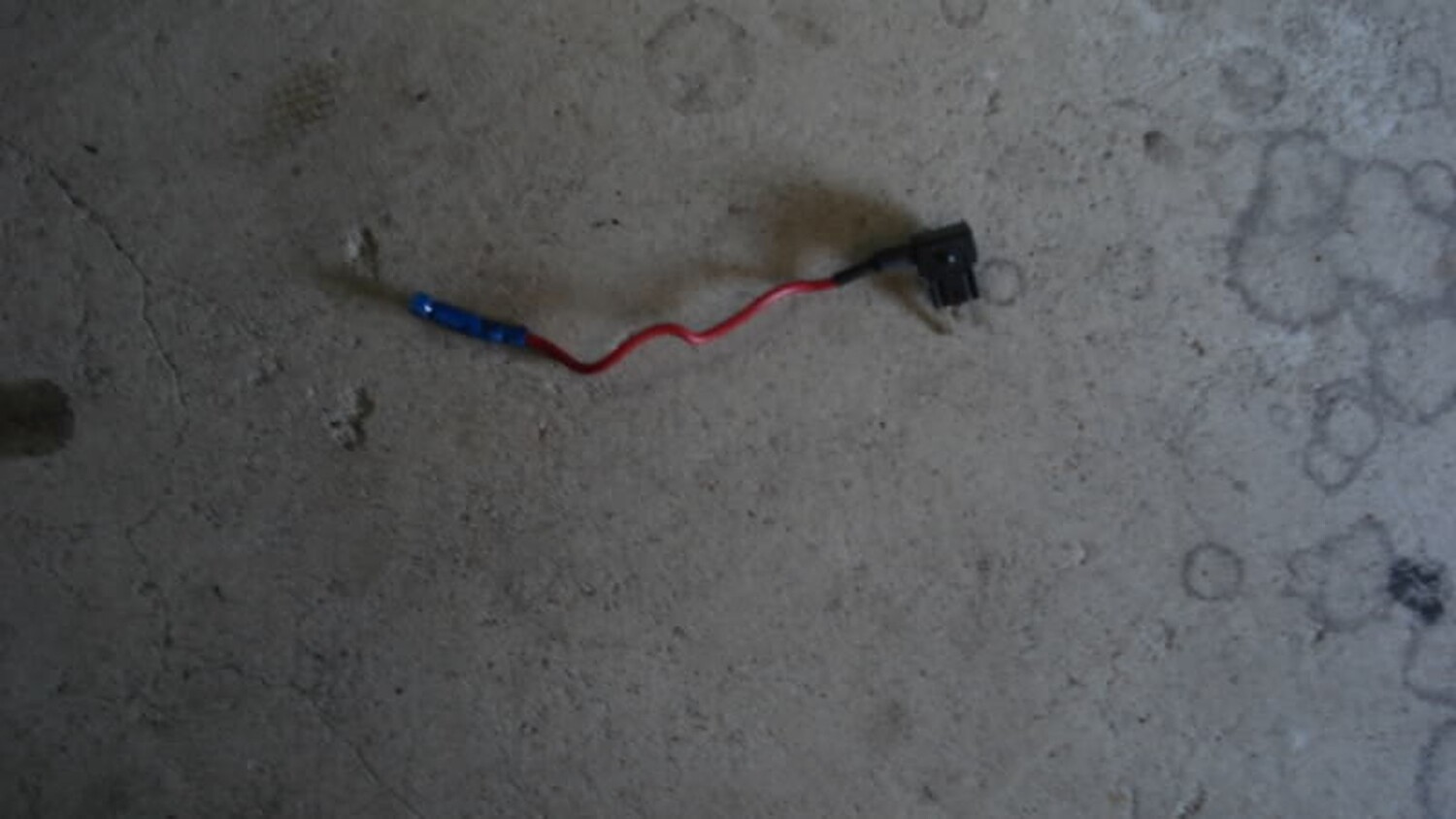
In order to use that same fuse I added a fuse tap
The tap has two slots to add fuses. One slot is used for the original fuse to work with the rear power sockets and the other is used for my new 12 volt source (tack module). Next step was to find a good grounding point
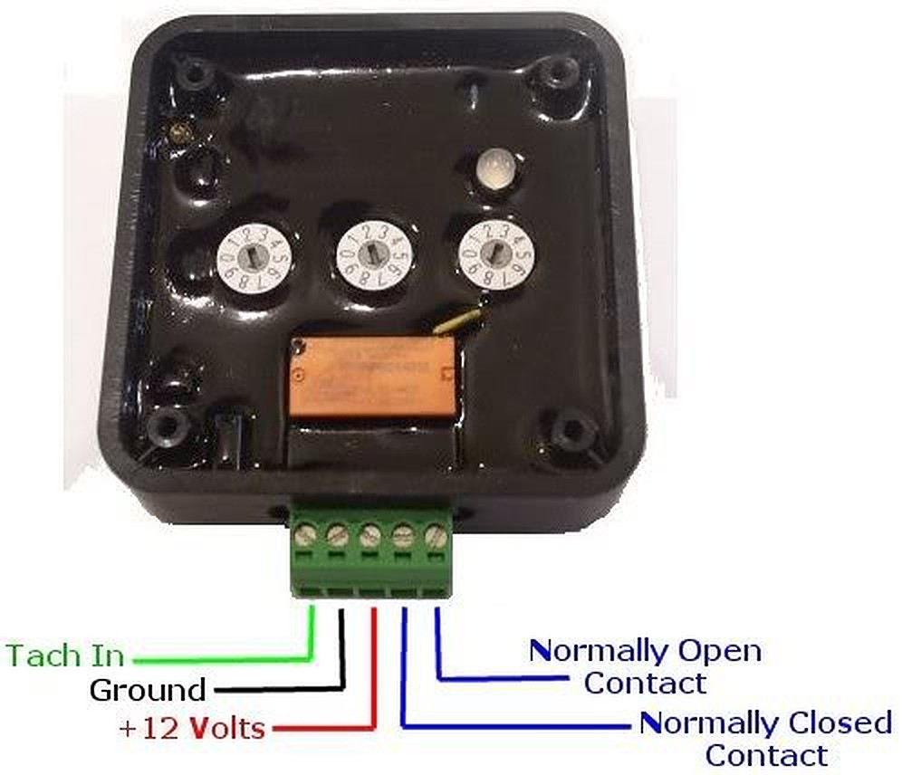
Now with the ground, 12 volt source, and tach signal connected we can now tap these wires into the harness that comes with the module. The harness has a green, red, and black wire. Green is for the tach signal and of course red for 12 volt and black for ground. The L.E.D ground will connect to the Normal Open Contact (see below ).
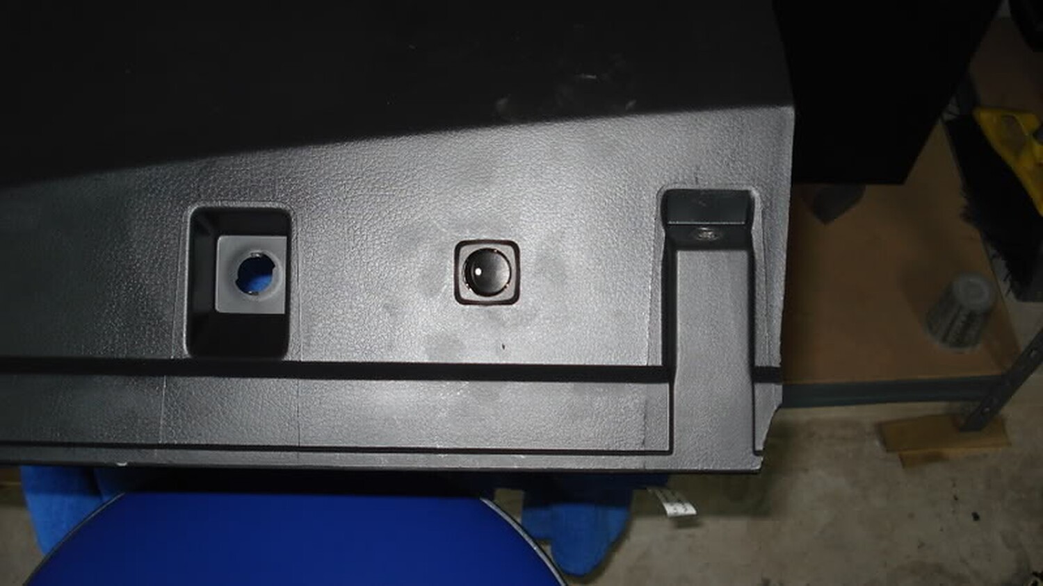
Now with the ground, 12 volt source, and tach signal connected we decided to install a switch so that I can turn on and off the module. I mounted the switch on the bottom of the panel below next to where the courtesy bulb connects. The 12 volt source from the fuse box connects to the switch and from the switch to the module.
The next step is to find a spot where you want to mount your L.E.D’s. The spot I chose was on the bezel that surrounds the odometer and tach. To connect the L.E.D’s you can connect the + wire to the 12 volt tap we are using for the module and the ground you will need to connect on the Normal Open Contact.
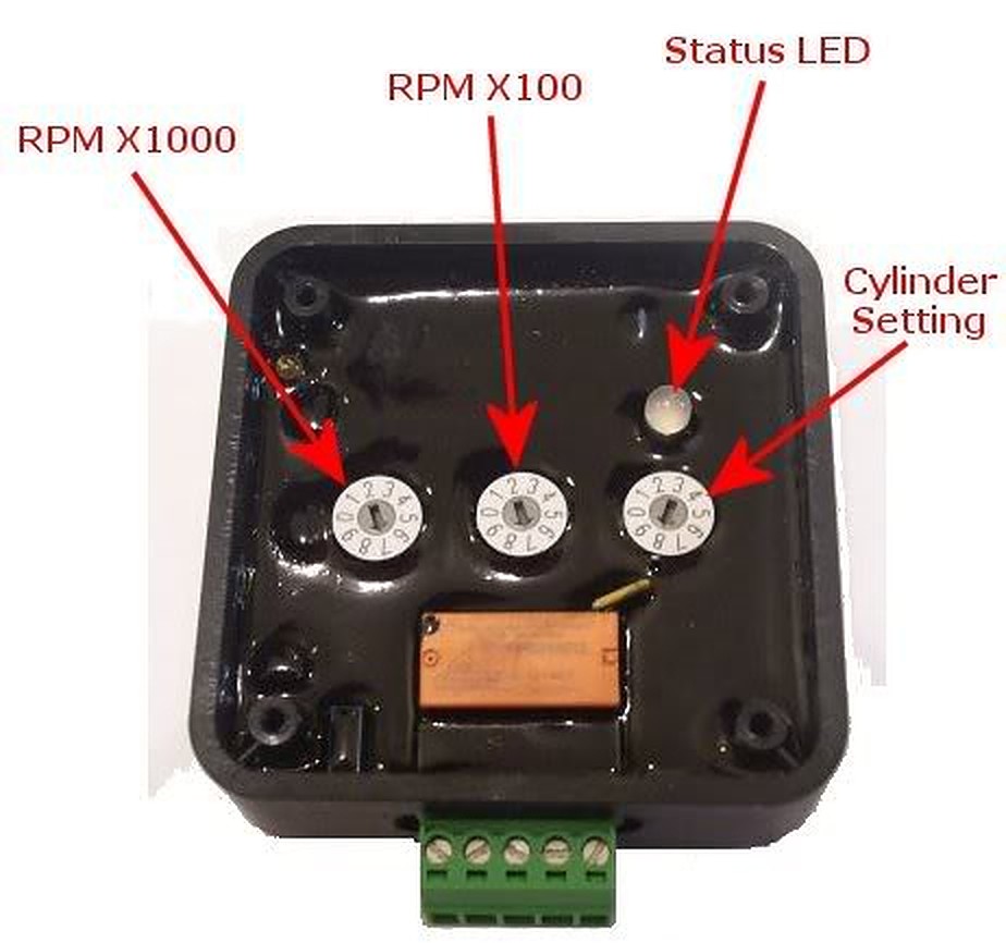
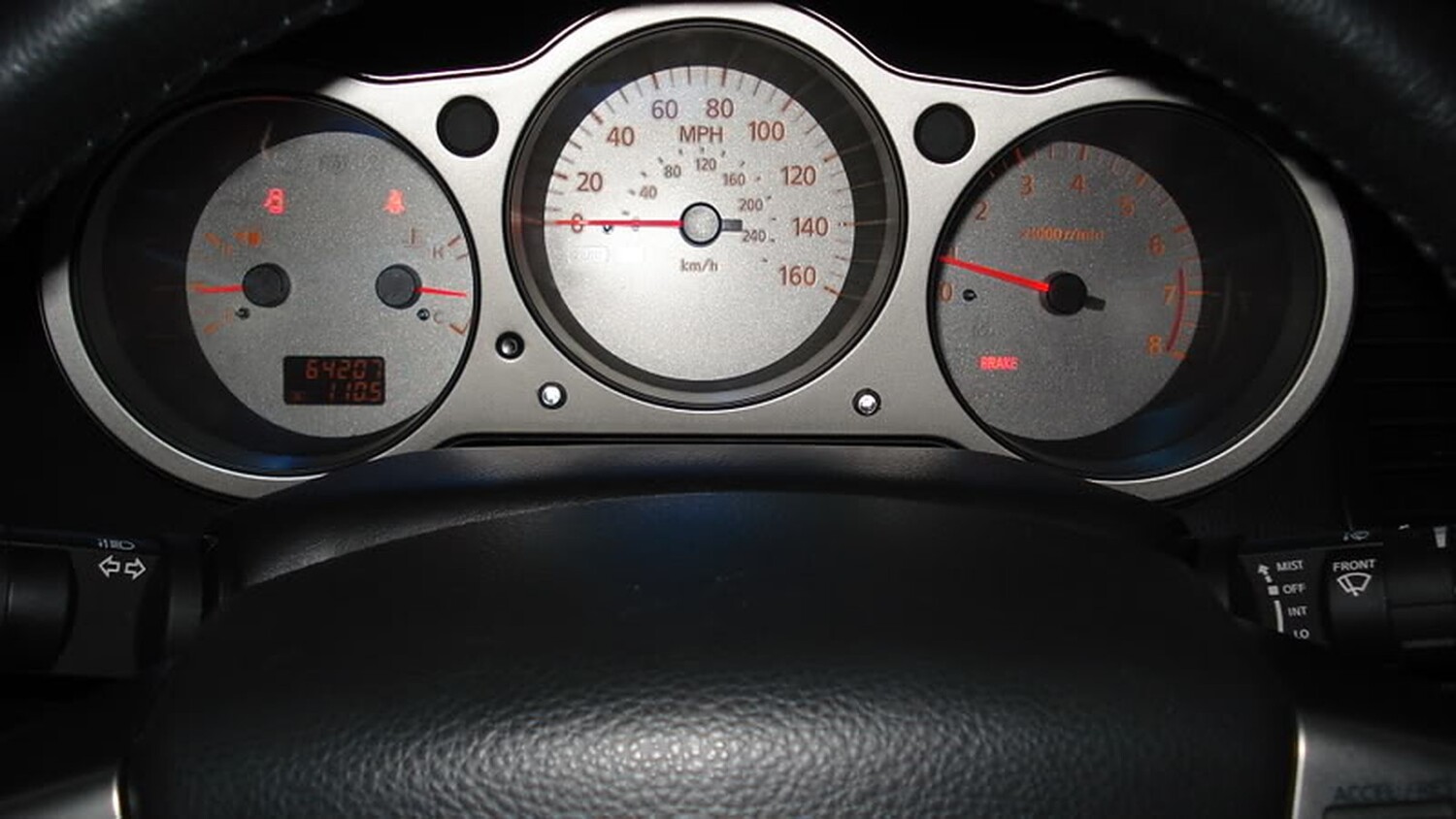
Now that we have all of this installed we can now adjust the dial on the module to your desire settings. In my case I wanted the module to send the signal to the L.E.D’s when the RPM would hit 6,100k. At 6,100K the L.E.D should light up and give me enough time to react and shift before redline.
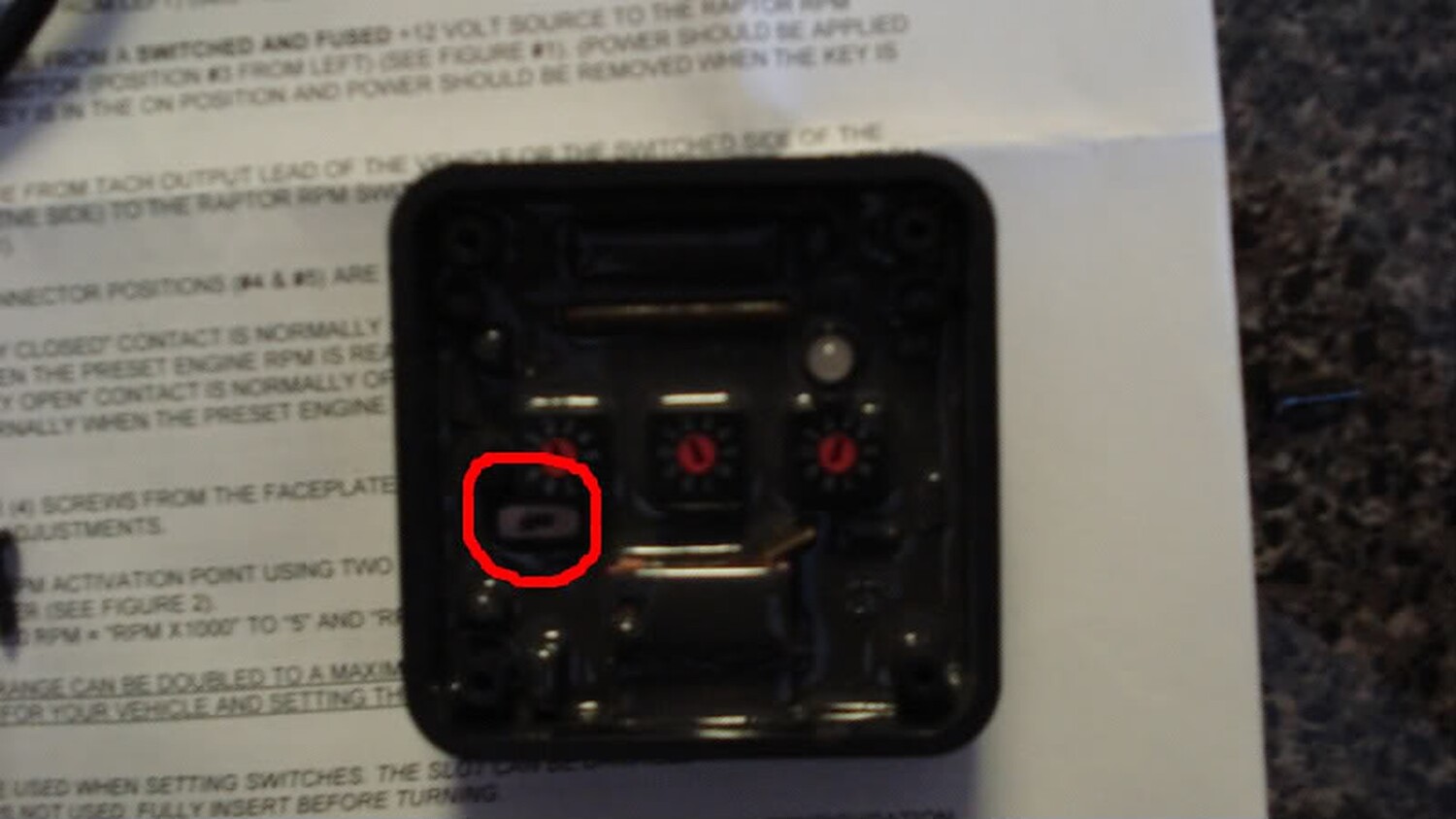
To do this I set the RPM X 1000 at 6 and the RPM X100 at 1. This gives me a dial of 6,100 RPM. If you want to do 6,500 you would set RPM X 1000 at 6 and RPM X100 at 5. Since we are only using one coil lead in our install you will only leave the cylinder setting at 1 on the dial. You will notice that there is a small toggle switch on the module. This switch was installed on the module in order to read a low volt signal from the coil.
Once you set your signal point on the module hook the harness to the module and turn on your ignition.
If the rpm switch isn’t picking up a signal after you program it (noted by rapid green LED flash), slide the small slide switch to the alternate position. Also, make sure your power switch is also on the “ON” position. If the install was done correctly you will see the following
A: The status LED will turn yellow and will flash the number of times which is representative of the RPM X 1000 setting
B: There will be a pause for about two seconds (no status LED flash)
C: The status LED will turn red and will flash the number of time which is representative of the RPM X 100 setting
D: There will be another pause of two seconds (no status LED flash)
E: The status LED will turn orange and will flash the number of time which is representative of the “cylinder setting” (in our case 1), and finally the module will do an LED test (alternating red & yellow) and be ready for use.
Once this is done close you module with its cover and install anywhere under the dash. I installed mine with double sided tape. Clean up the mess and enjoy.
Here is a video of how it works on my car. BTW, I want to thank my other half for helping me record the vid.
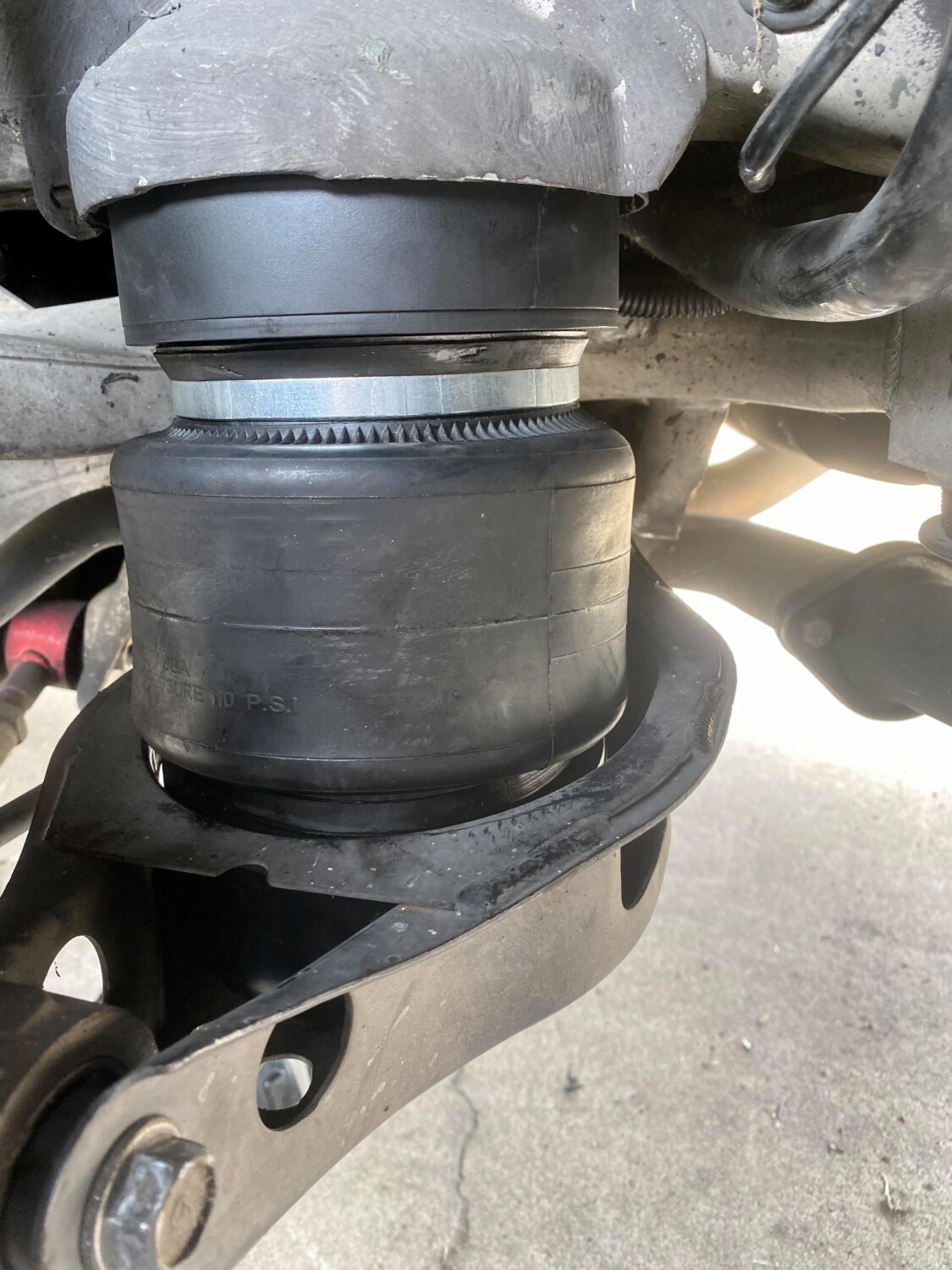
Front Bags: “Aero Sport” By Universal Air Part # 02-ST-SB-14 ($220 Each)
Rear Bags: “Air House 2” By Universal Air Part # 02-2600 ($79 Each)
Front Mounts: If your front strut mounts are bad and you want to do UAS front mounts, they are $350 for top and bottom CNC custom. Include both sides. Only if you need it.
Rear Brackets: You will also need brackets for the rear. You will need to call as they are not listed on UAS Website. You need two sets and they are $69.00 each. So $138 for brackets.
Accuair Air Management System
XO Luxury Madrid Wheels
20×10.5 +28 Front w/ 245-35-20
20×11 +28 Rear w/ 245-35-20
Old Front Struts
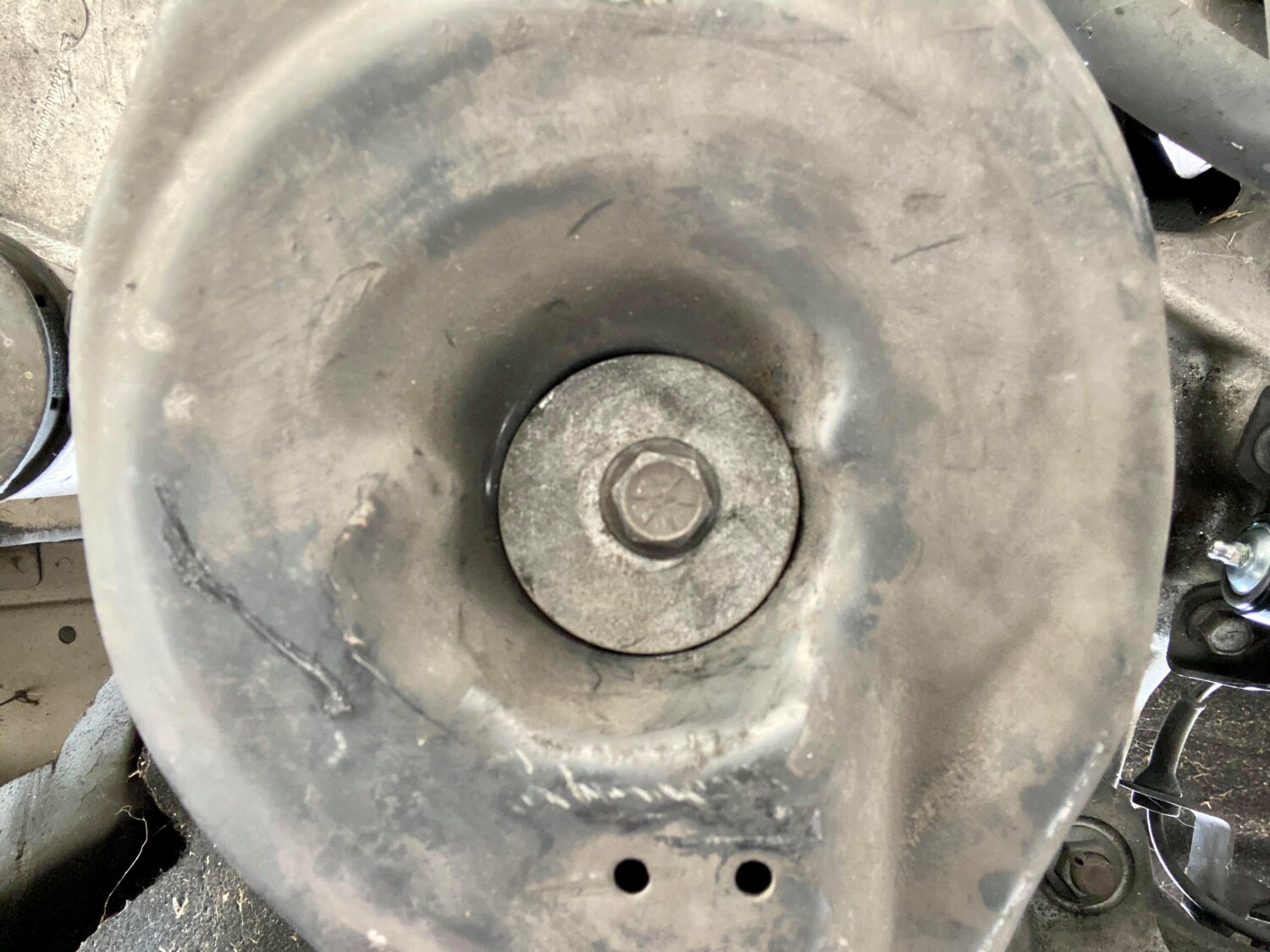
Hand-tighten the washer and bolt underneath the bag. This will help secure it. Be gentle as you can mess up the threads. Do not use an impact.
I went to start my car using the auto start and it stalled. I got the car checked and it threw code P0340 Camshaft Bank 1 Position Sensor Malfunction. Below is my guide to the repair.
Symptoms
Car hesitates to start
Car manual mode is stuck in 5th gear
Car slams into R & D
Car won’t go over 2500rmp
Check Engine Light came on
Error Code P0340 was thrown
DISCONNECT BATTERY FIRST!!!
If your stock remove your filter intake portion first using a flat head screwdriver. Disconnect your MAF sensor ( while your here this would be a good time to use MAF sensor cleaner as I did ) Using pliers remove the vacuum hose carefully and remove the rest of the intake box and set it aside. Now move on the upper tube that’s connected to the intake manifold and using the flat head loosen that connection. Set aside that tubing as well Now that you have the room you be able to access the bank sensors better, in this case, were going for Bank 1 which is the green clip located closer to the firewall but just at the base of camshaft near ignition coil 1 as well ( Bank 2 is closer towards the front almost 6 inches from Bank 1 in the direction facing the car bumper still with the same green clip. Using a 10mm socket and extension remove the bolt holding the sensor in place. There is also a small clip holding the sensor harness against a plate to remove this clip so you can manage the sensor better.
Now, this is the hardest part. the clip is a weird design intended to almost never let the sensor go. it involves you pushing up and then pulling down in order for you to release the sensor from the holder and its a pain in the ass to remove.
In case you get the sensor off replace with part # 23731-6J90B which is bank 1. Replace all parts in the order they were taken off. Clear your CEL and all set.
UPDATE from Robert Mandru: Have both the 300zx and 350z bracket adapters. They will NOT clear with Evo X 2 piece rotors, maybe just 1 piece. Even with one piece it still wouldn’t clear the inside, rotor too large with the 350z/G35 adapter. The EVO X top hats are too big and will not allow the calipers to bolt up. Probably could do it with the 300zx adapter without modding the caliper but for god sake, you have smaller bolts that are supporting all the strain coming from holding the caliper in place during braking conditions. Not worth it.
In simple terms….. do not bother with the eBay 300zx Caliper Adapters
If you are looking to upgrade to Nissan 370z / Infiniti G37 Akebono Calipers, then below is the information you need to know when using the Autosports Engineering brackets. The brackets are decently priced and work fine. however, various members have reported some pad “overhang” which has varied (some worse than others). But other than that the brackets work fine and there have been no issues or functionality impacted with the overhang.
Important Note: These brackets for only for the front calipers. The rear Akebono calipers are plug-n-play but only for the 04+ Maximas/Altimas. All you need to do is trim the dust shield as it’s a much bigger rotor.
If you are reading this article, you are very likely trying to resolve P0420/P0430 without having to spend a lot of money on the issue. Most of the time, the codes are due to a bad clogged catalytic converter or bad O2 sensors. Before replacing the O2 sensor, be sure to do the spacer fix modification first because O2 sensors are not cheap.
There aren’t usually any drivability issues associated with these codes. For most people, the first sign that anything is wrong at all is the check engine light. Below are the typical check engine lights you would normally get:
P0420 NISSAN – Catalyst System Efficiency Below Threshold Bank 1
P0430 NISSAN – Catalyst System Efficiency Below Threshold Bank 2
The Fix
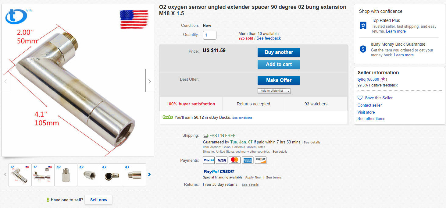
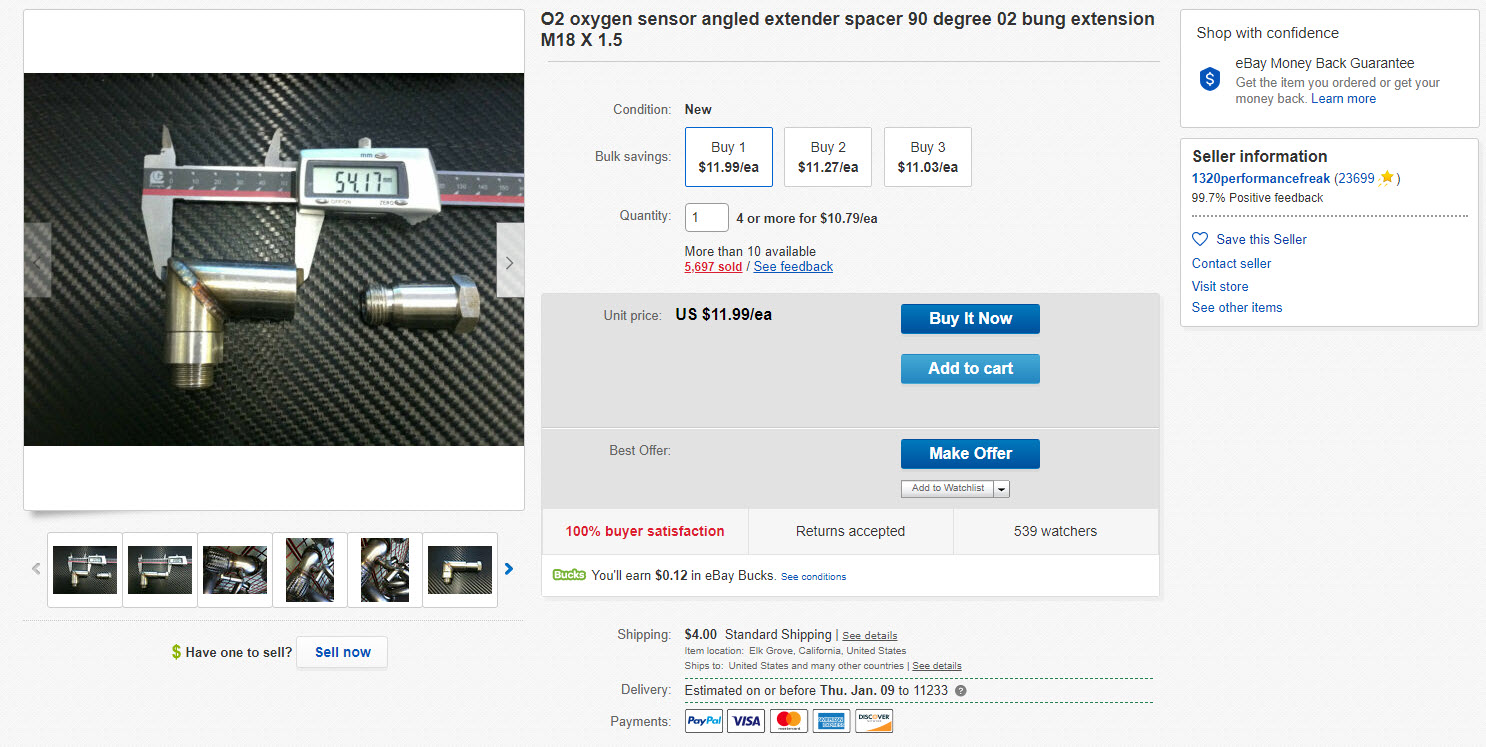
You can eliminate the codes by using a spark plug non-fouler which tricks your engine computer to think that everything is working fine. This simple trick will pull the O2 sensor away from the exhaust flow and the computer will think the Catalytic converter is working properly. This will work if you remove the catalytic converter or have a bad cat. It’s very simple and cheap to do. Below is a video on how to perform the fix:
You can also buy them pre-made on eBay if you do not want to drill.
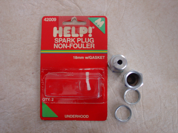
Make Your Own Spacers/Foulers
You can buy these non-fouler spacers at your local parts store. You can get them from Advanced Auto or Autozone for about $7-8 bucks.
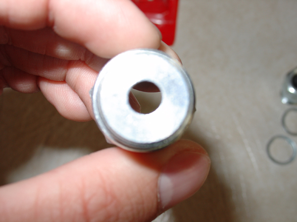
You now need to drill out 1 of the non-foulers using a 1/2″ drill bit. When finished this is what it will look like.
O2 Sensor inserted in the modified non-fouler
Second, unmodified non-fouler now installed on modified non-fouler, then threaded into the pipe
Reference Photos
Below are photos of the spacers installed and 100% working on Nissan Maximas by generation. After installing the spacers, the CEL codes went away.
Disclaimer: If you attempt any of what you see from my post, you do so at your own risk. The following is a summary of my experience.
The Car: 2002 Maxima SE Transmission: 6 speed, HLSD, RS6F51A Mileage: 174,000 mi. (approx.) Situation: November 1st, 2014. I jumped in the Maxima, running late to a funeral in Tennessee. Pushed clutch to floor and started it. I could not get gear shifter out of third gear no matter how hard I tried. Something was obviously broken in the transmission.
After a lot of online research, I purchased a 29,066 mile 6 speed, HLSD transmission from a 2006 Nissan Sentra Spec-V (p/n RS6F51H) from http://car-part.com/. Kindly gentlemen cargo shipped it from a junkyard in Arkansas to my door step in North Alabama for $XXX (will update when I remember it). The following were the only differences in the two transmissions: (1) bellhousings were different, (2) final drive ratio were different (3.812 vs 4.133), (3) Maxima – 1st & 2nd gear dual synchro, SpecV – 1st gear dual synchro, 2nd gear triple synchro.
Sentra SpecV Transmission As Received:
Work Setup:
Set each transmission on cardboard covered work bench side by side (cardboard to protect mating surfaces on transmission and soak up any grease/oil/fluids)
For fasteners, blow up and print out FSM pages and glue to cardboard. Poke fasteners through on board where you take them out of transmission
Take off parts from each transmission at same time, label in Ziploc bag
For large parts, label and place in its own cardboard box
Clean as you go (scrape off gasket material, use acetone/cloth) to clean
Follow both factory service manuals for breakdown/buildup
Maxima
SpecV
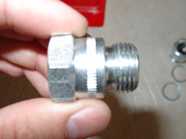
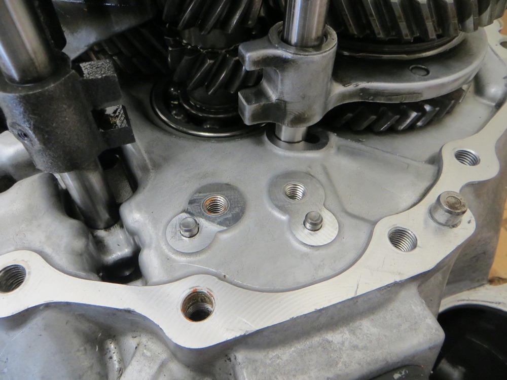
Maxima Speedo Sensor Block-off Plate
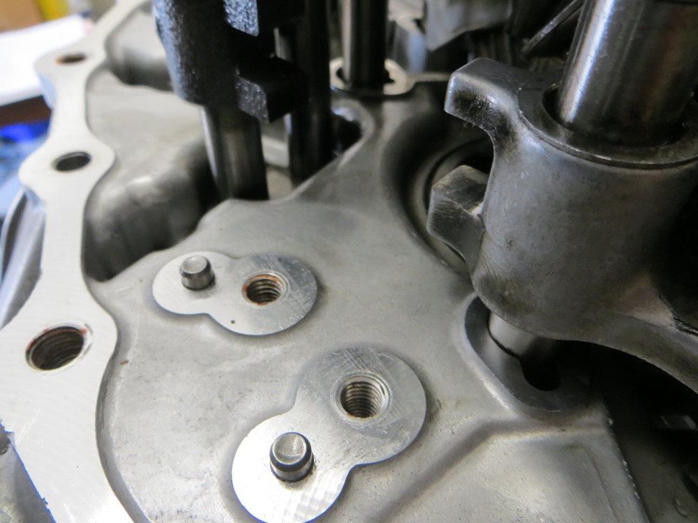
SpecV Speedo Sensor
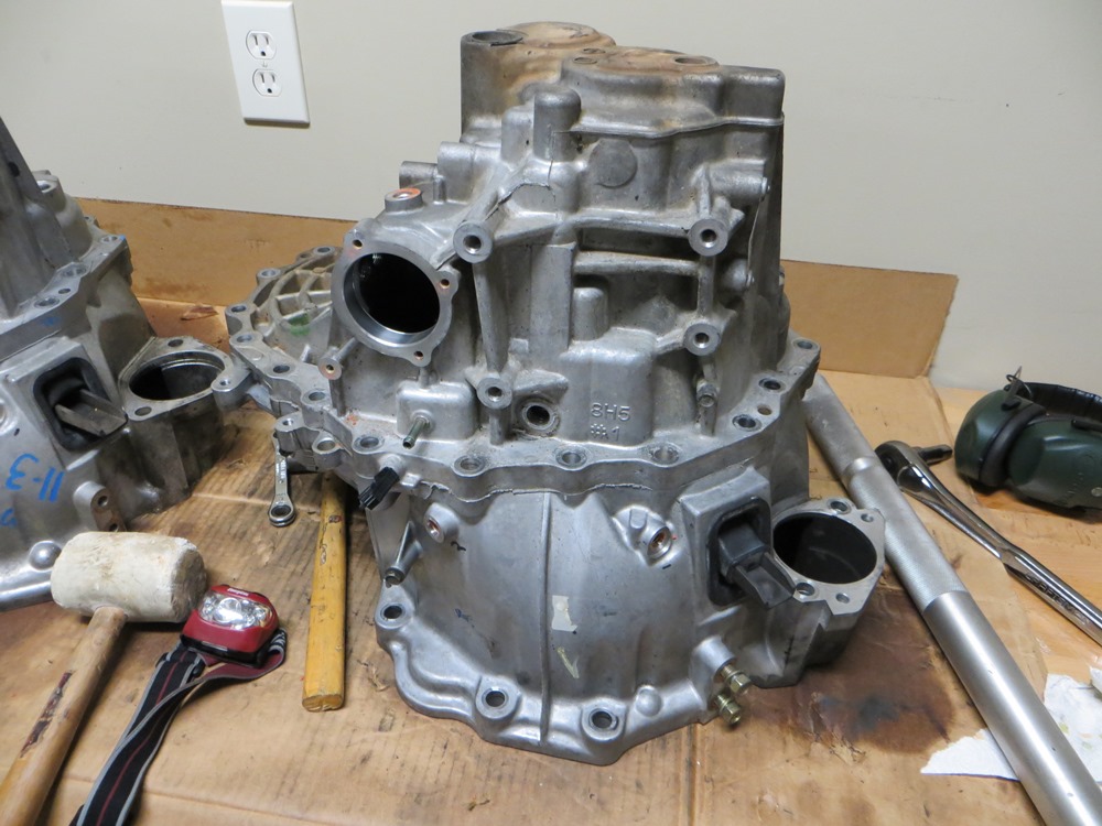
Maxima Transaxel Case Stamp
SpecV Transaxel Case Stamp
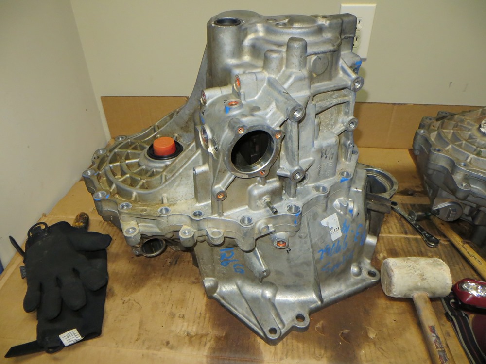
Maxima
SpecV
Maxima Control Assembly, Sensors, and Case Bolts Removed
SpecV Control Assembly, Sensors, and Case Bolts Removed
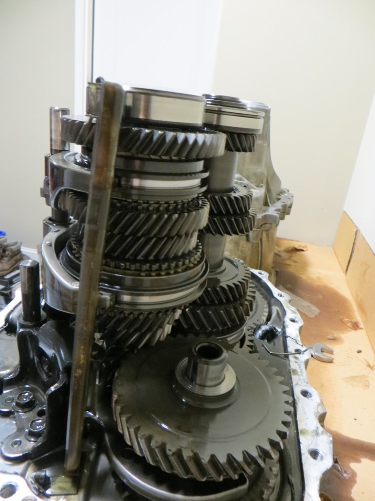
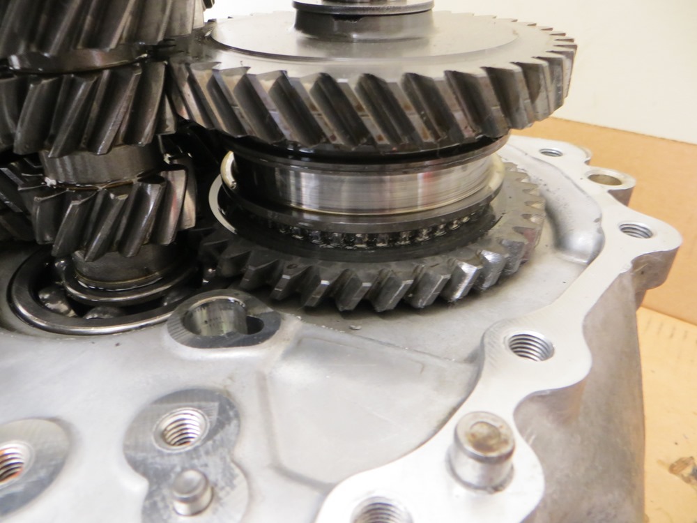
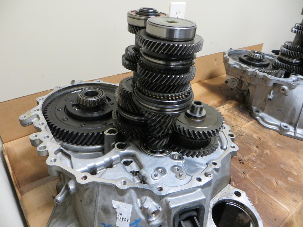
Maxima Transaxel Case Removed (at this point forward, they both look the same
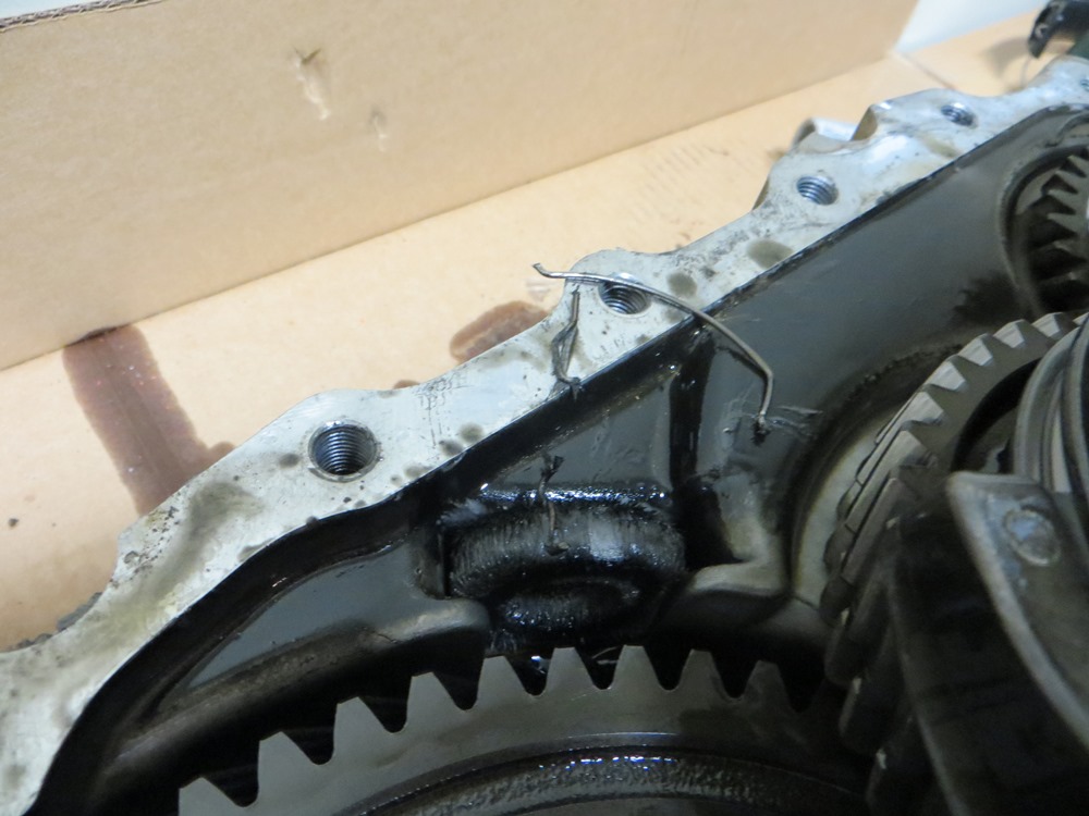
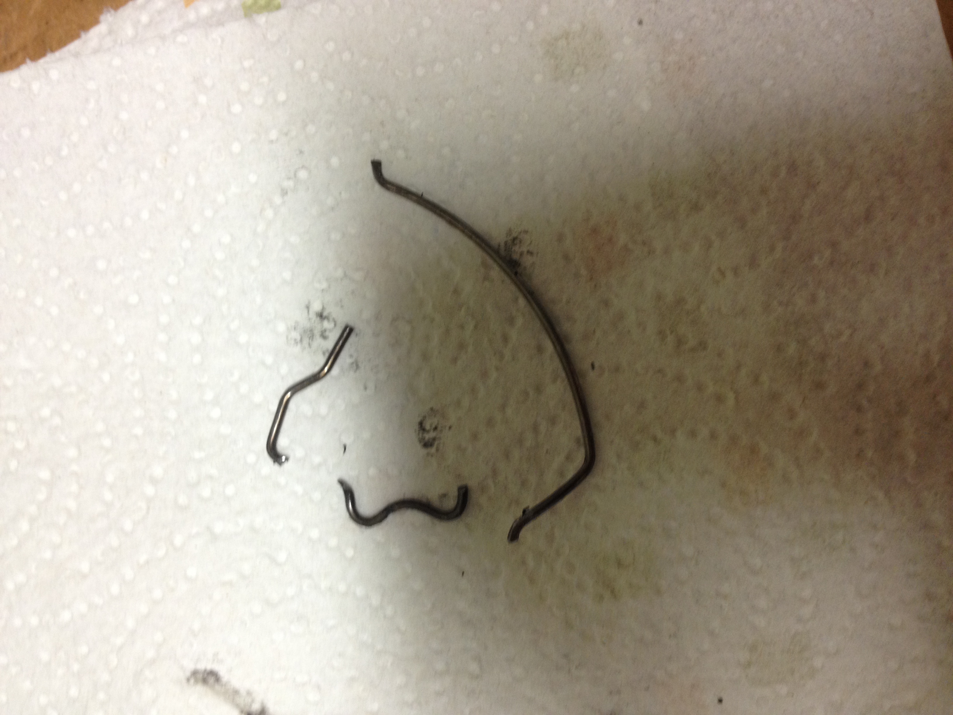
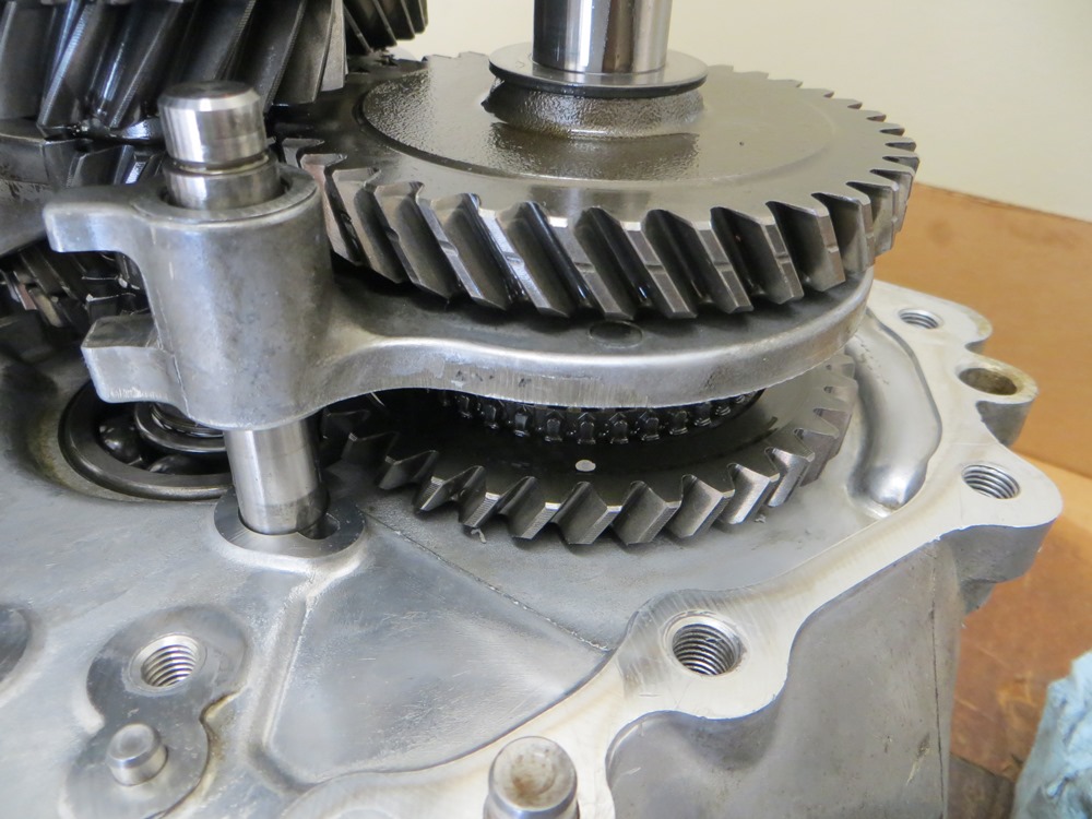
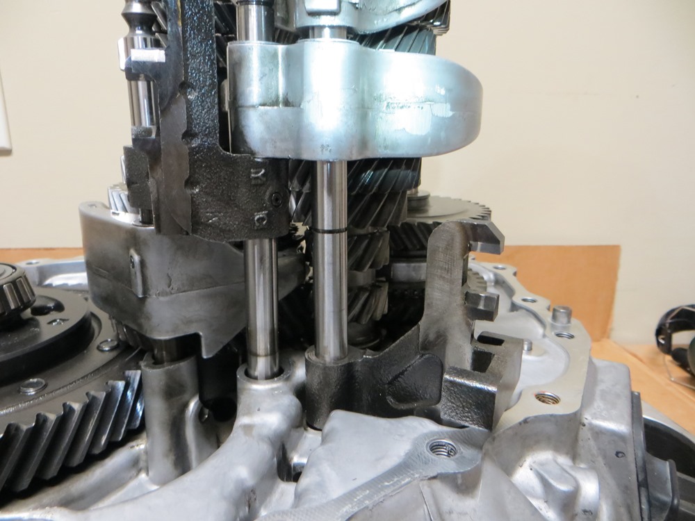
Maxima Spread Spring Debris and Detail
Based on the pictures below, it appears the spread spring in the 3rd-4th synchronizer broke and lodged itself in to prevent the sliding action between gears.
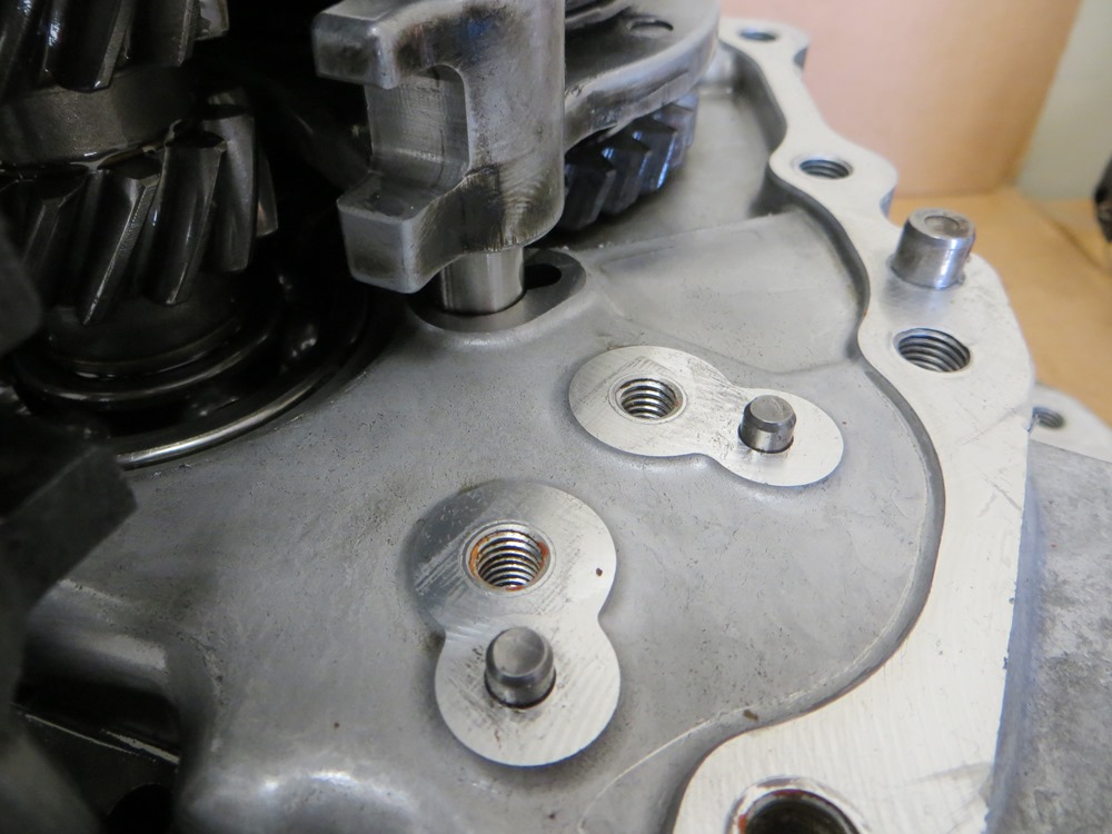
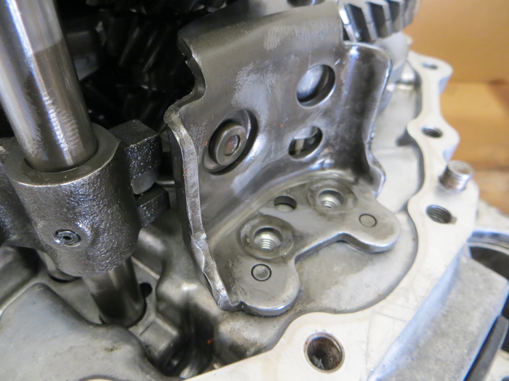
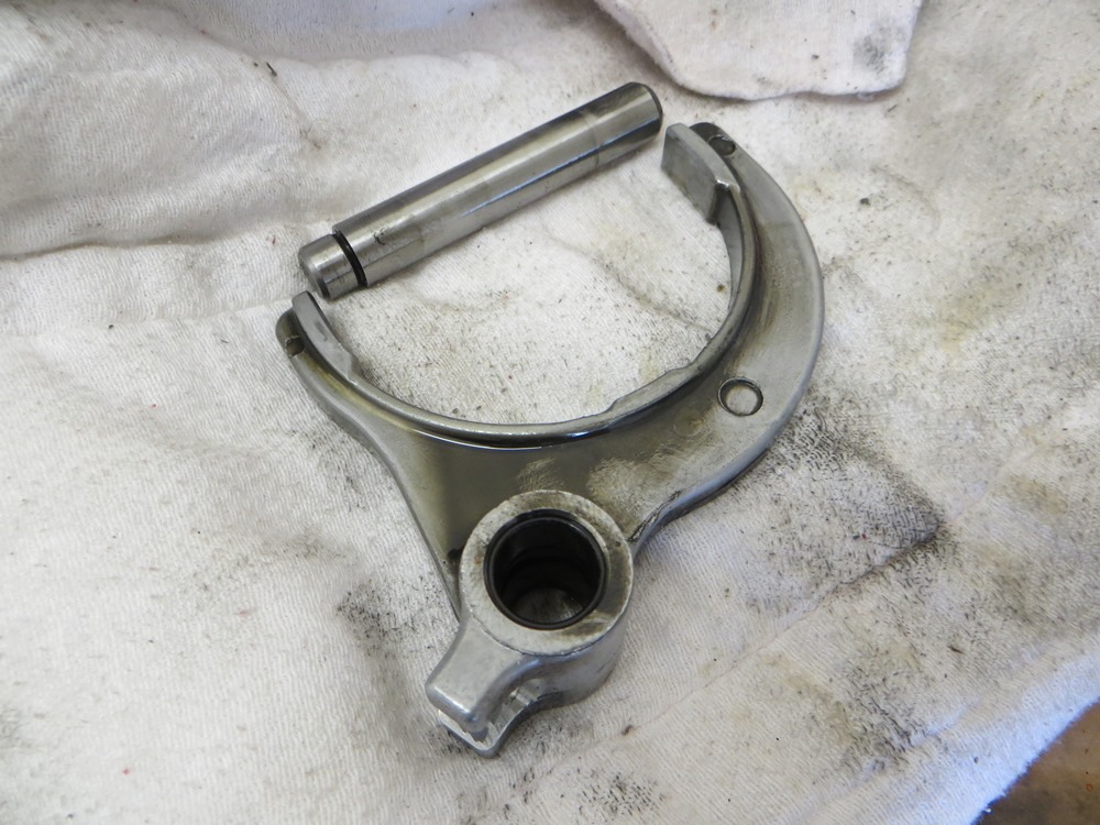
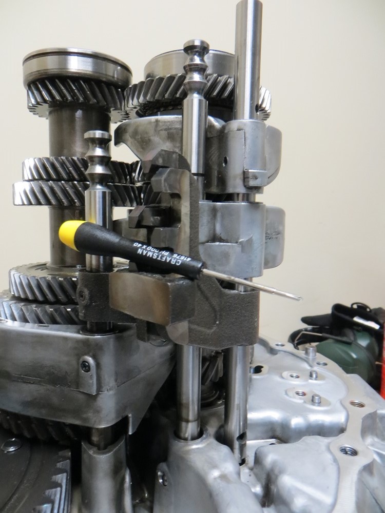
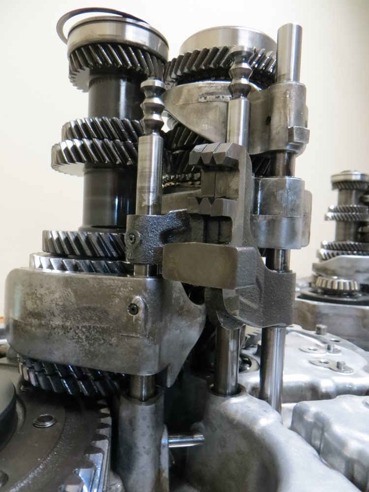
Maxima – Reverse Tilt Mechanism Removed
Maxima – Re-test fitting reverse tilt mechanism (to make sure I understood its reassembly)
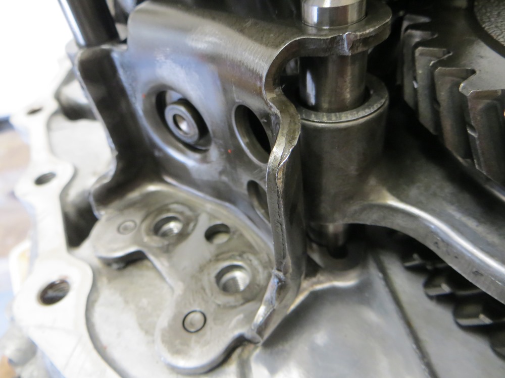
Maxima – Reverse shift fork and rod
Maxima – Reverse Gear Stack
Maxima – Re-test fit reverse shift fork
Maxima – Shifter bracket Detail
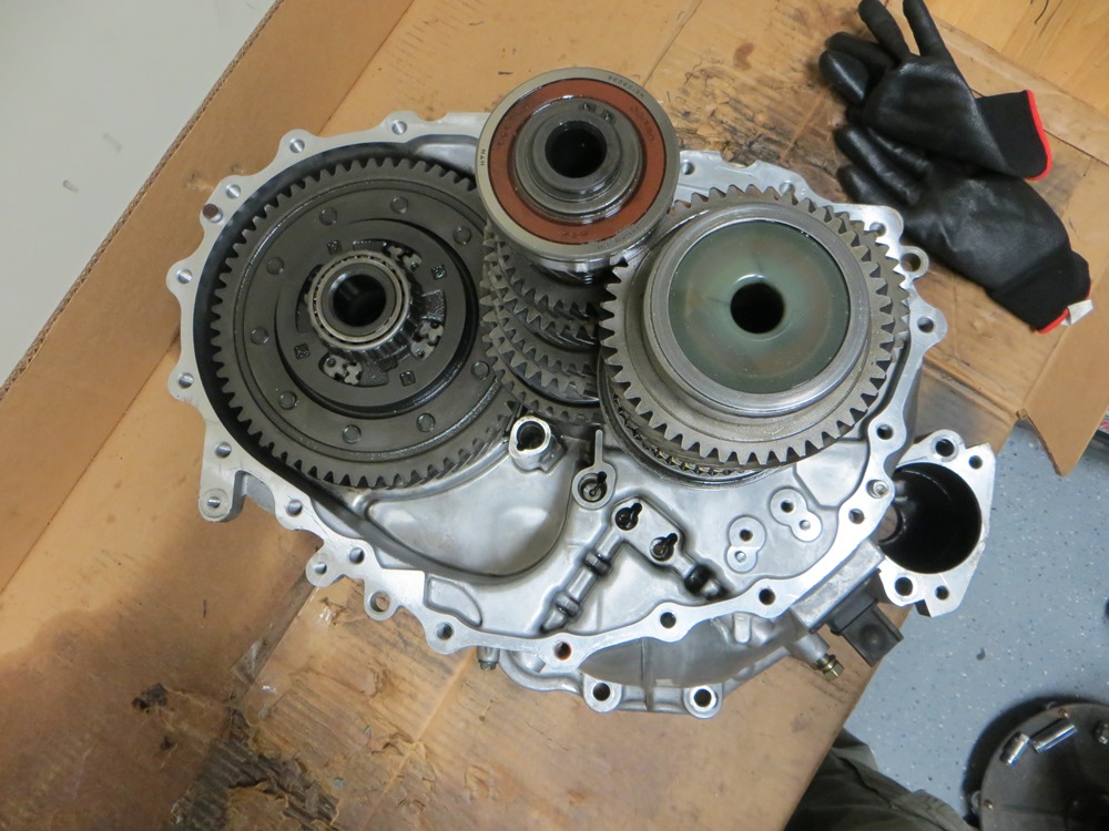
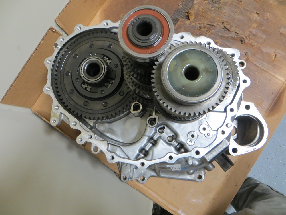
Maxima – Gear Stacks and Differential
SpecV – Gear Stacks and Differential
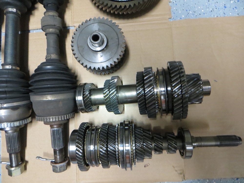
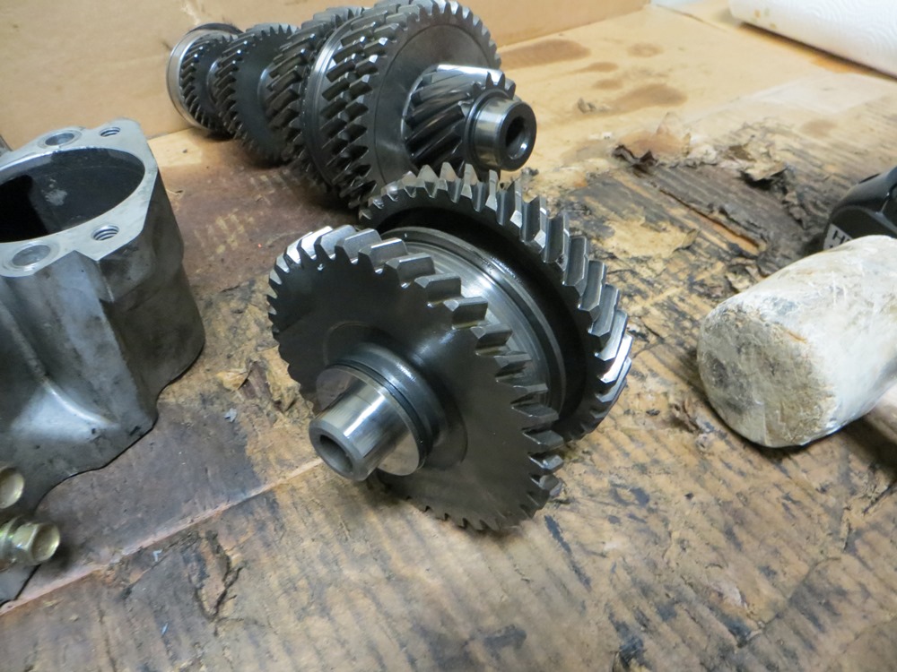
Maxima – Input, Main, & Reverse Shafts and Axels
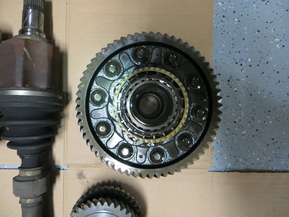
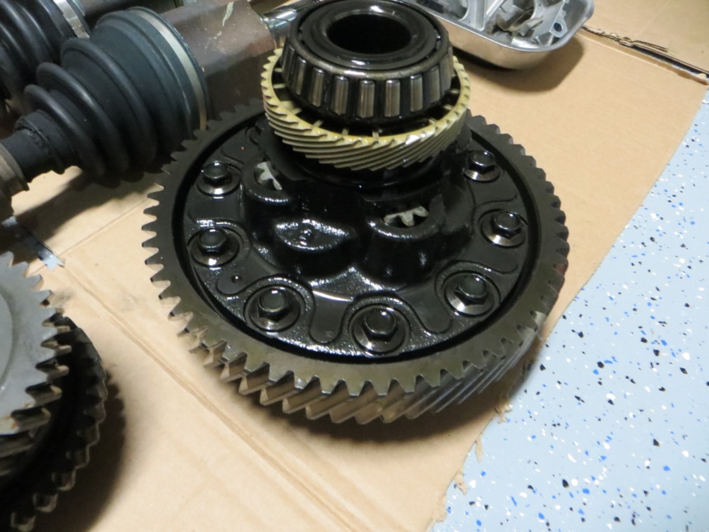
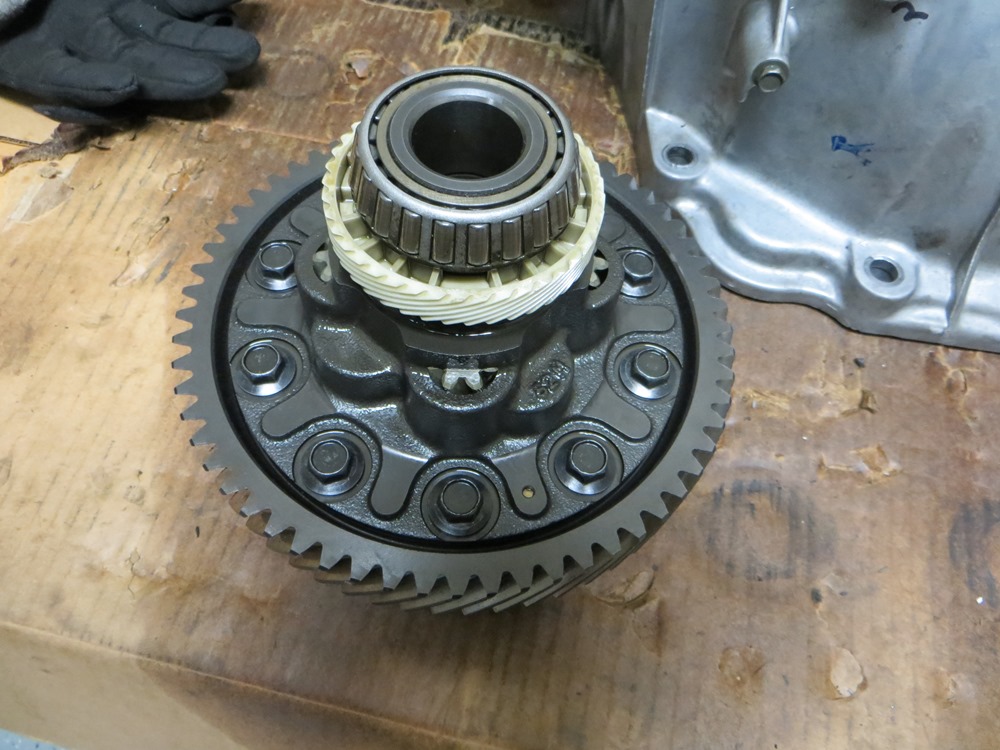
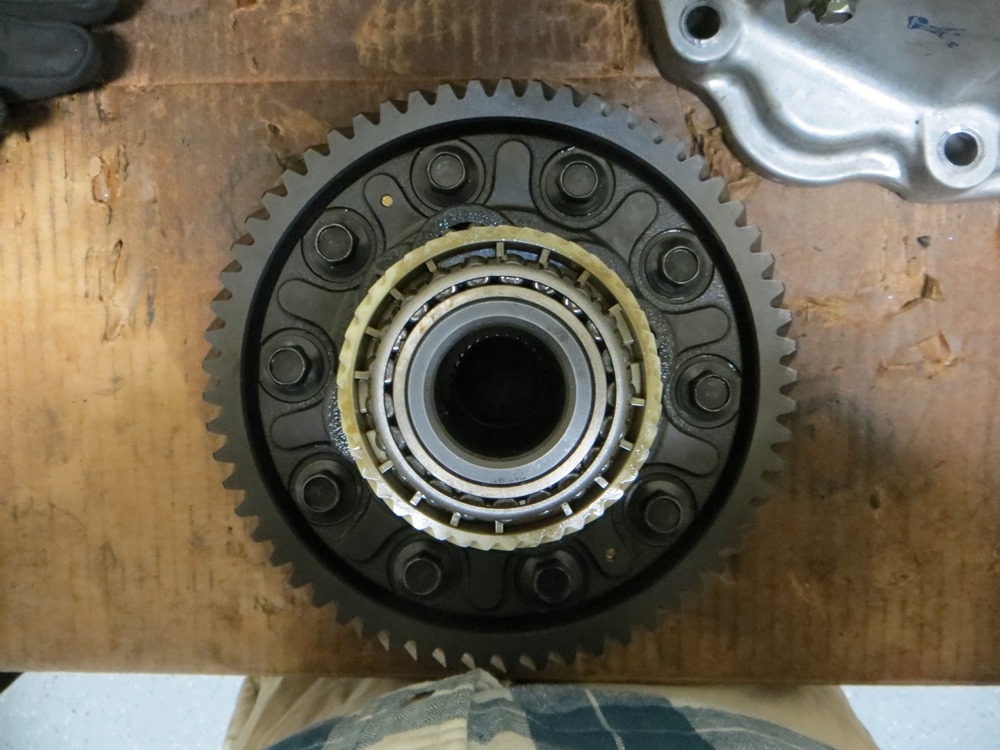
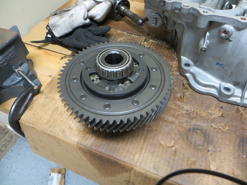
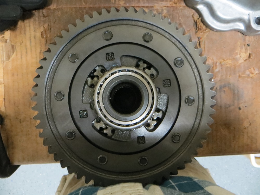
Maxima – Final Drive & HLSD
SpecV – Final Drive and HLSD
SpecV – Reverse Gear Set
Cleaned Maxima Bellhousing (Used acetone and cloth)
Cleaned Differential Side of Bellhousing
Maxima Final Drive and HLSD from SpecV
SpecV Reverse Gear Set
SpecV Gear Stacks and Maxima Final Drive in Bellhousing
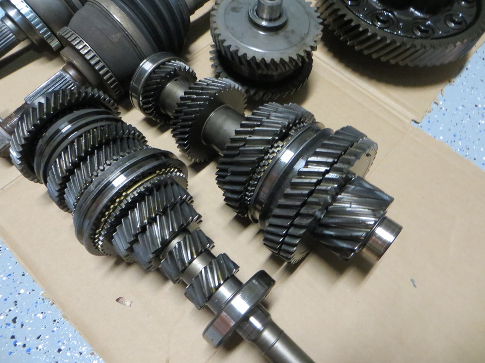
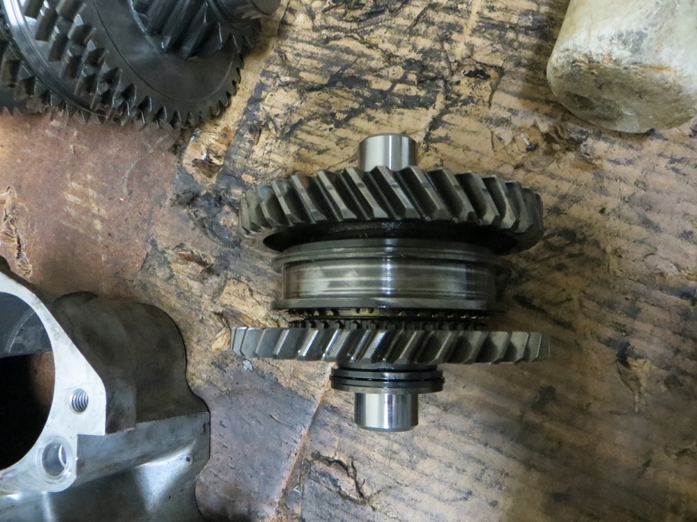
Maxima Final Drive Meshed with SpecV Mainshaft
SpecV Mainshaft Meshed with SpecV Input Shaft
SpecV Input Shaft Meshed with SpecV Reverse Gear Set
Detail SpecV Main and Input Shaft
SpecV 5th/6th Shifter Fork with Maxima 5th/6th Shifter Fork Rod Detail
The SpecV 5th/6th Shifter Fork Rod had a pretty significant burr on it, and wouldn’t actuate properly. So I used the Maxima version.
SpecV Check Ball and Spacer for 5th/6th Rod
SpecV 1st through 4th Shifter Fork with SpecV Rod Detail
SpecV 1st/2nd Shifter Fork Detail
SpecV Reverse Bracket Detail
SpecV Reverse Shifter Fork Detail
SpecV Reverse Tilt Mechanism Assembly
SpecV Check Ball and Spacer for Reverse Rod Mechanism
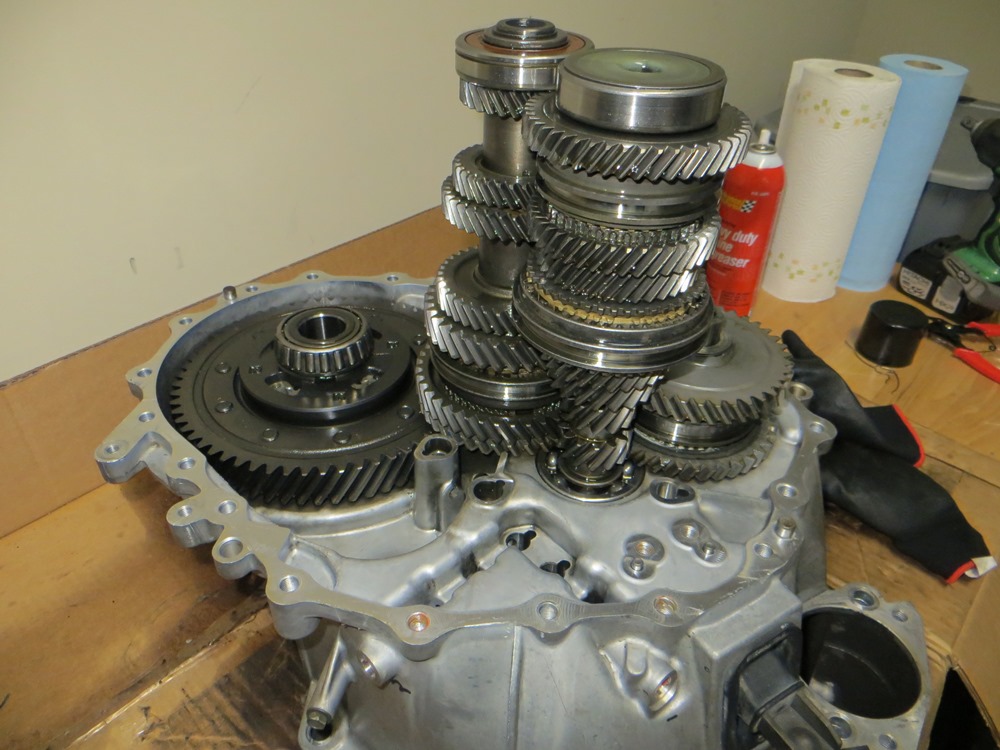
Fully Assembled SpecV Guts and Transaxel Case on Maxima Bellhousing


")


 Disconnect your MAF sensor ( while your here this would be a good time to use MAF sensor cleaner as I did )
 Using pliers remove the vacuum hose carefully and remove the rest of the intake box and set it aside.
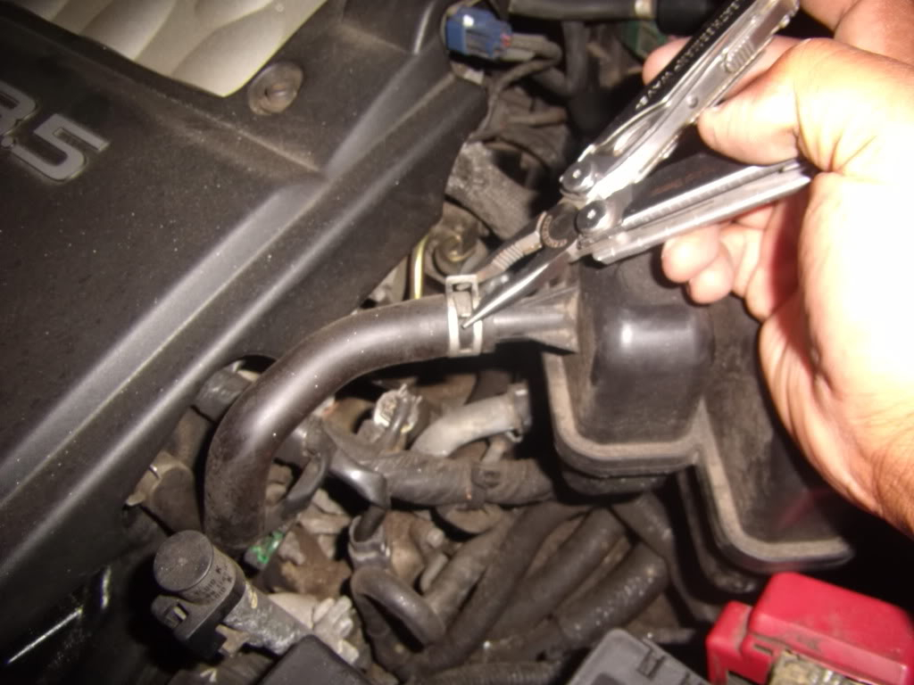
 Now move on the upper tube that’s connected to the intake manifold and using the flat head loosen that connection.
 Set aside that tubing as well
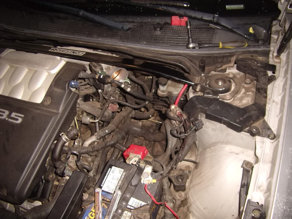 Now that you have the room you be able to access the bank sensors better, in this case, were going for Bank 1 which is the green clip located closer to the firewall but just at the base of camshaft near ignition coil 1 as well ( Bank 2 is closer towards the front almost 6 inches from Bank 1 in the direction facing the car bumper still with the same green clip.
 Using a 10mm socket and extension remove the bolt holding the sensor in place.
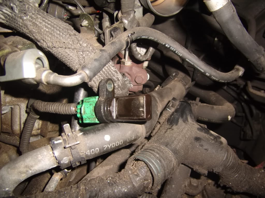
 There is also a small clip holding the sensor harness against a plate to remove this clip so you can manage the sensor better.
 Replace all parts in the order they were taken off. Clear your CEL and all set.


")


")