Both the Nissan 370Z and the Infiniti G37 calipers are the same size, simply done in different colors respectively. They both will interchange 100% with each other, and all hardware remains the same for both calipers.
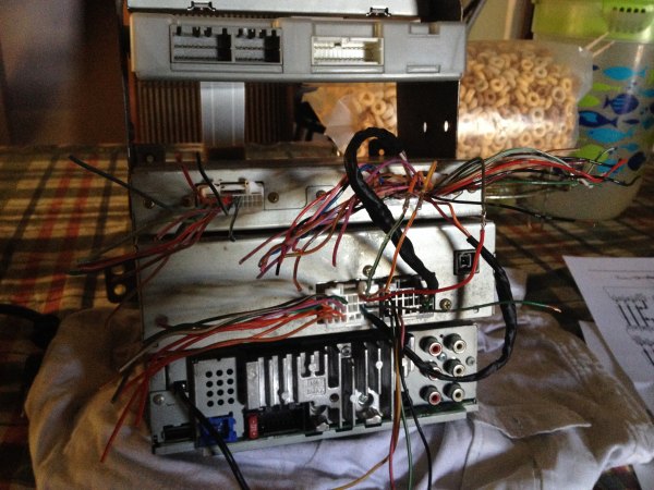
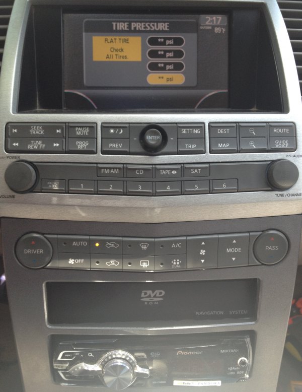
1. Navigation Display Screen (28090 CA100)
2. Display Control Unit (28330 ZC00A)
3. Navigation Unit (25915 CB804)
4. GPS antenna (I bought an aftermarket one that works)
5. Plugs that fit the back of these units (Just searched for Nissan plugs on eBay and bought what seemed to fit).
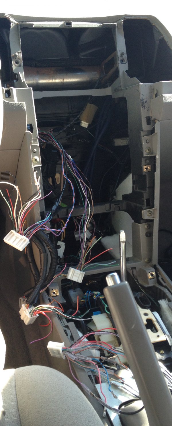
The Display Control Unit and Navigation Unit came off a 2005 Infiniti QX56. I didn’t buy any special wiring harness, but be prepared to wire 50-70 wires. Most of these wires are interconnected with the control units mentioned above, and only about 20 wires need to be connected to the car.
The schematic for the integrated display system is on page 70 and for the navigation system on page 111.Choose your year, then it’s under the “av.pdf”.
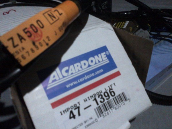
I just wanted to share my experience, I now have all 4 windows auto up/down and all 4 roll up/down with the remote on my 2005 Nissan Maxima.
I had to buy:
The master switch with all auto switches.
The rear auto switches.
Rear window power motors. The new motor has 6 wires and the original has 2 wires. The new motor has a sensor that tells the window where it’s located, open vs closed and everywhere in between.
Rear door harnesses specifically made for the 4 seater Maxima. The new rear power window motor and rear switches use a different electrical connector.
Note: I had to do some rewiring at the master switch to send the two needed connections to the rear windows.
I sent the Power Window Serial Link and the BAT from the master switch to the rear switches. The auto switches you can get used from a Maxima that had those, the auto rear ones are on eBay right now.
The left harness is 24127-ZA500 and the left window motor is 47-1396. The right components have similar part numbers.
Separate the chrome finisher from the shift knob by pushing it down.
Remove the shift knob (1) by removing the spring clip and pulling up. Then remove the chrome finisher (2).
Set the parking brake.
Pull up to release the clips and remove CVT finisher.
Disconnect the bulb housing from the assembly.
Pull up on the rear portion of cluster lid C, once the 4 bottom clips are disengaged, pull rearward to release molded clips at the top of cluster lid C.
Disconnect the electrical connectors.
Remove front air control, storage bin, hazard switch, aux in jack, and power outlet.
Remove cluster lid D screws using power tool.
Pull cluster lid D toward rear of vehicle to release clips.
Disconnect the electrical connectors.
Remove the audio switch (if equipped) and the center vent ducts.
Remove the screws (1), disconnect electrical connectors and remove the center stack (2).
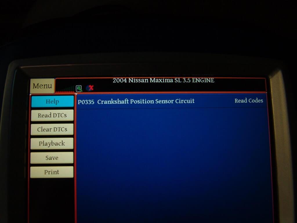
This 2004 Nissan Maxima came in with the complaint that the transmission would not shift properly. The customer stated it felt like the transmission was starting in a high gear. I really did not want to work on this vehicle as the customer informed me that the engine and transmission had both been replaced with used parts. You just never know what you will run into when going behind someone else. First the code checks.
Code P0335 stored in the PCM. although the customer had not complained about it, I had noticed that there was an extended crank time before the engine started.
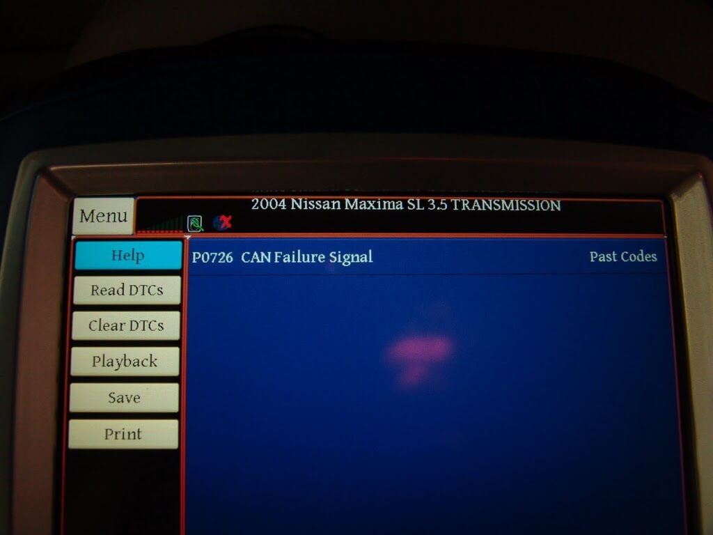
The TCM had a code P0726 stored for a CAN Failure system. In case you were wondering CAN stands for Controller Area Network. This means that there is a communication problem between modules.
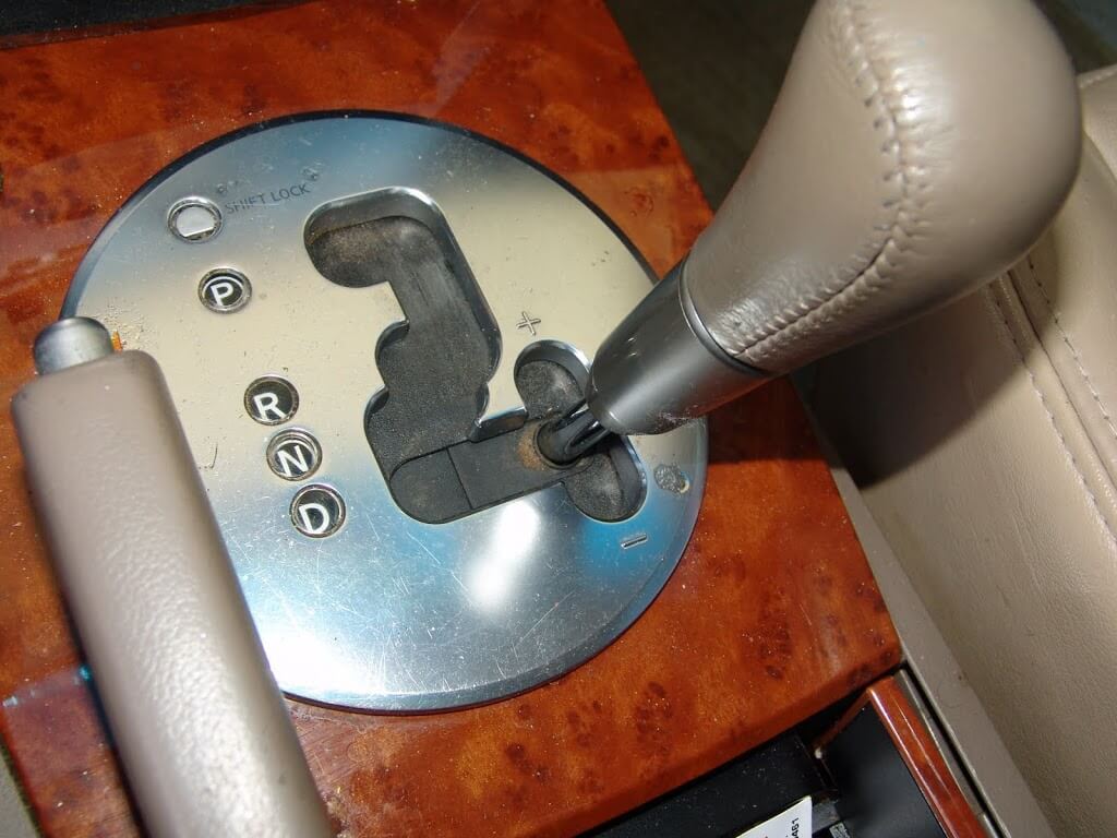
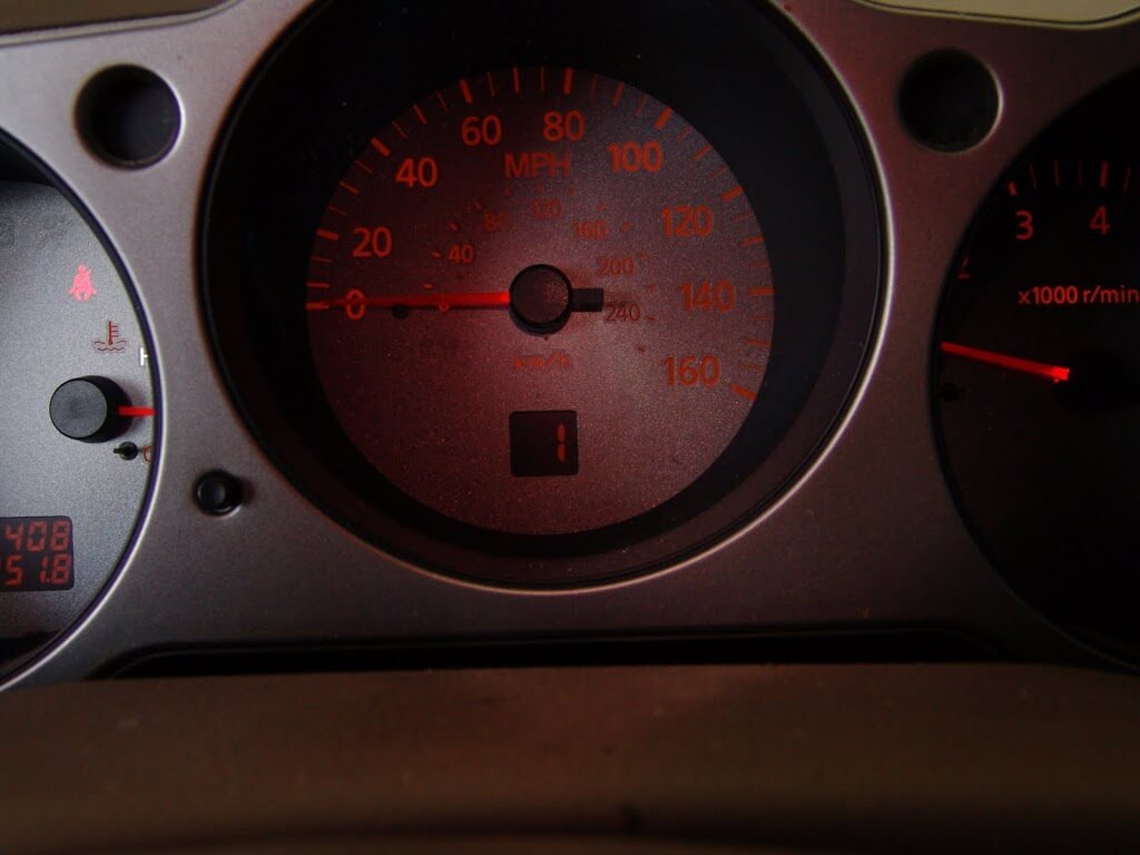
With the key on and the gear selector in the manual shift position the gear indicator in the instrument cluster shows that the transmission is in the 5th gear.
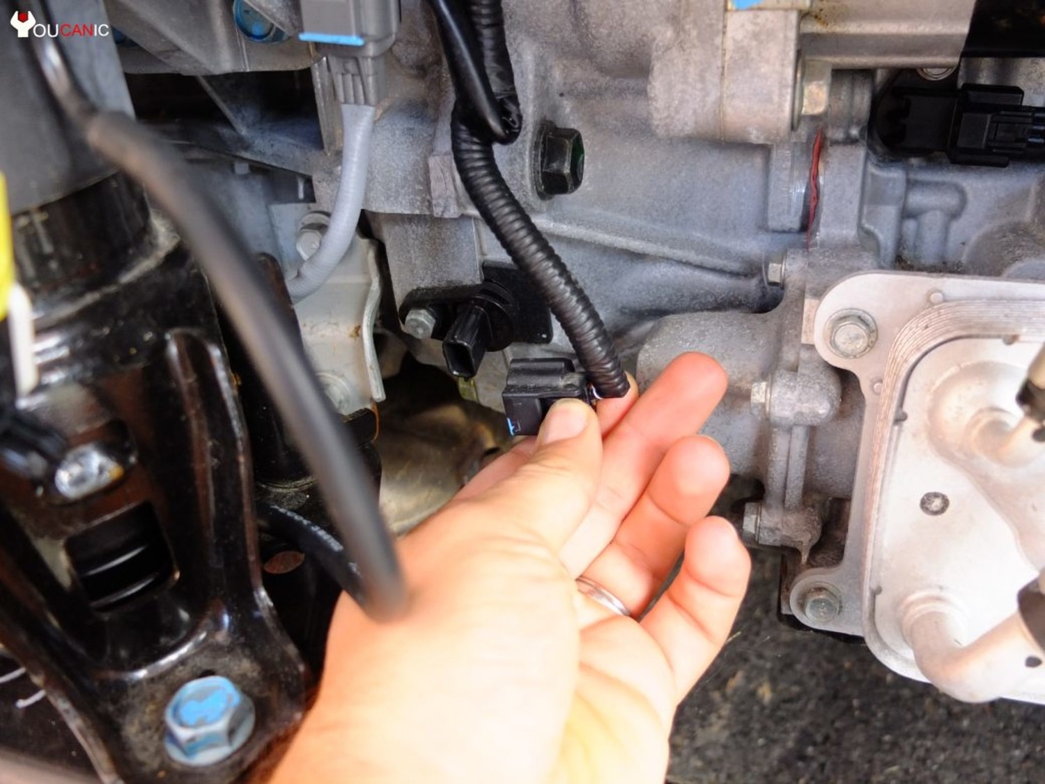
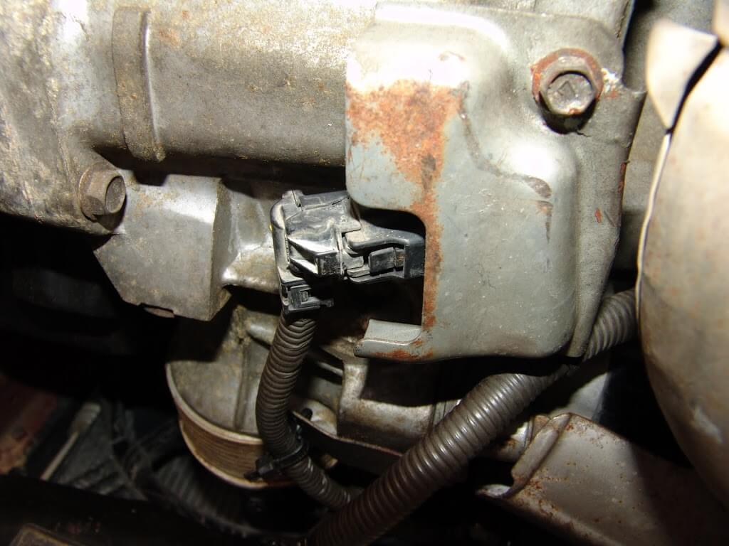
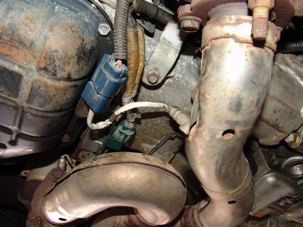
I wanted to do a little research, in that I have never seen a code P0726 before and I wanted to know a little bit more about it. I found that there are some real world anomalies with the factory diagnostic procedures. The TCM is supposed to use a crank sensor signal along with other data to determine shift patterns. The real world has found that cam sensor signals are also involved with this process. The engineers it seems did not plan on this or they did not inform the service information writers about it. Since I did have a crank sensor code I decided to start there. The crank sensor is located at the bottom center of the engine just below the flywheel area.
Everything looks okay here or does it? Kind of strange how the end of the connector looks like it is lined up perfectly with the edge of the sheet metal shield. A gentle pull revealed that it was not fully seated.
Could it be that it was that simple. This vehicle had been to two other shops before arriving at mine. Using a pry bar, I straightened out the sheet metal shield.
Then installed the connector until the lock snapped into place.
Of course while I was looking around at the problem I noticed quite a few things out of position.
Gee, you think a wiring harness laying on an exhaust pipe might cause some problems?
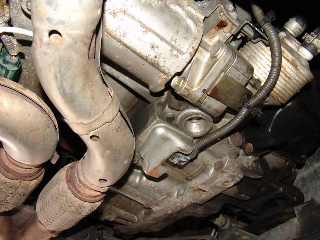
It amazes and worries me that someone can actually get an engine and or transmission in and out of a vehicle and leave something like this a mess. I had to round up a few bolts and finish installing a couple for brackets and heat shields. Then reroute the oxygen sensor wiring so that it would not be laying on the exhaust.
It does not look too bad now but I informed the customer that the engine installation needs to be gone over to make sure nothing else is loose or not installed.
Now the shift indicator shows that the transmission is in 1st gear. Both the PCM and TCM codes are now gone. The engine also starts as it should.
This one will be back in a few weeks to finish going over the wiring under the hood.
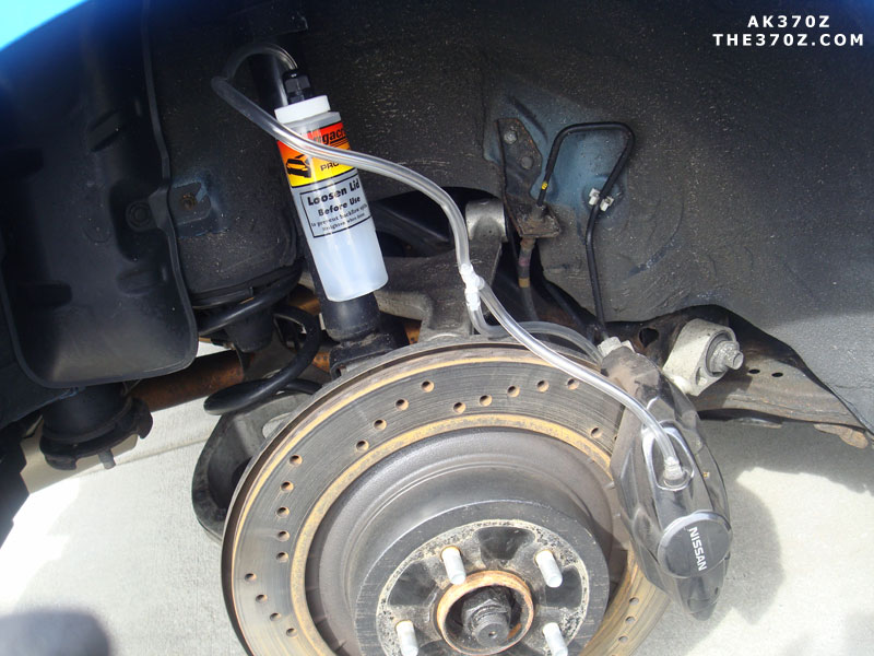
I recently replaced the ABS Actuator on my 2004 Nissan Maxima. Since the job requires removing the brake hard-lines, you will need to bleed all of your brakes to get all the air pockets out. Easy enough right??
Well……. I bled the brakes 4-5x times and the pedal still kept going down to the floor. Literally, no pressure at all. I started to think that I didn’t tighten one of the hard-lines properly or the calipers were bad. But I didn’t notice any brake fluid leaks or issues.
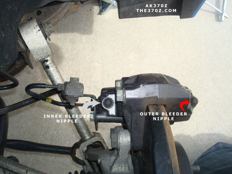
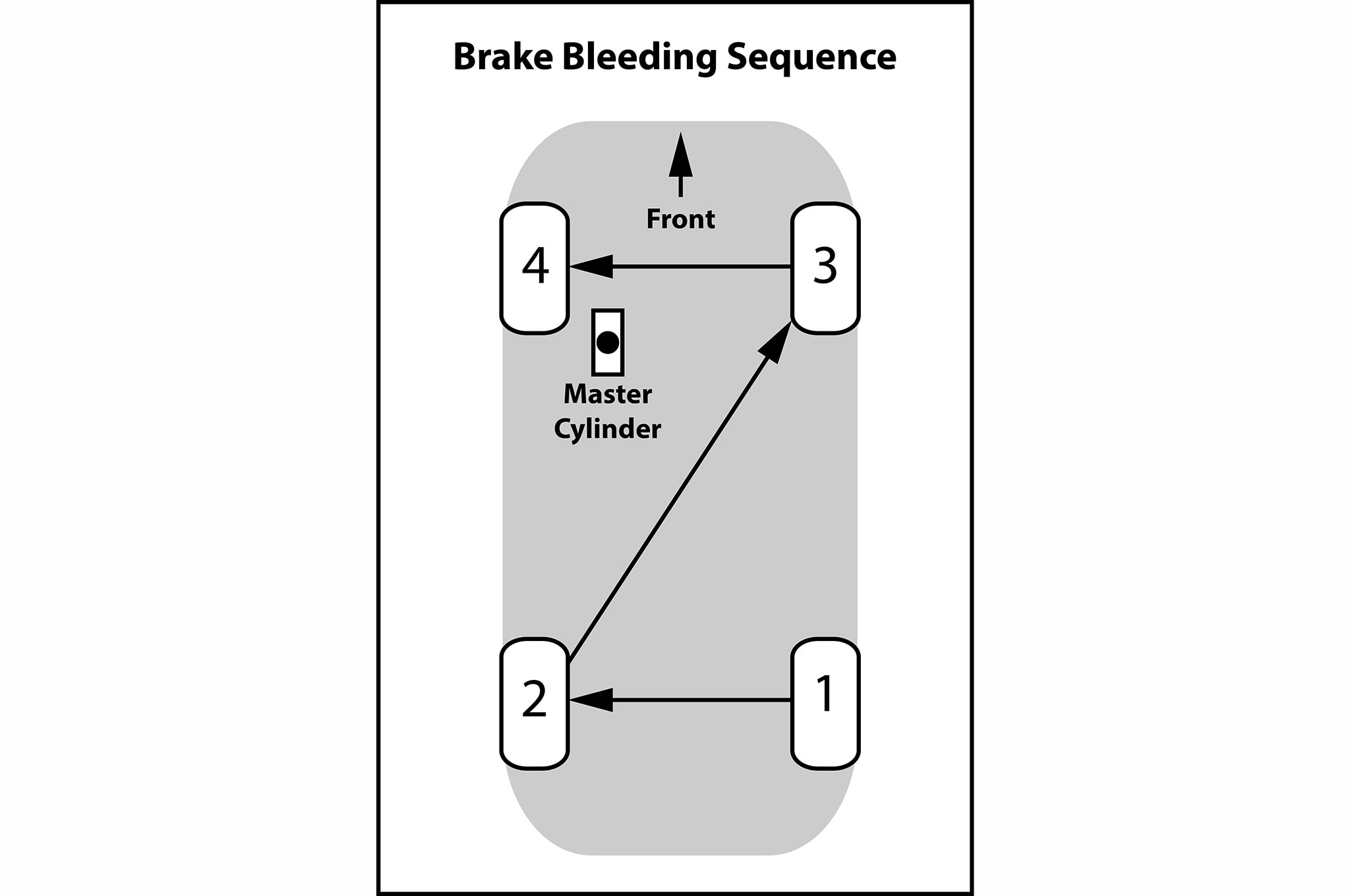
I reached out to my buddy Raul (@tuneonthego) and he asked if I bled both the inner and outer bleeder. I definitely did not do that (and totally didn’t even notice the inner valves). You are supposed to bleed the inner valve first and then the outer. I went back and did both following the standard bleeding procedure.
AND VIOLA….. brakes were solid and no longer going down to the floor. In total, you have to bleed 8 bleeder valves. Hope this helps someone who has the same issue.
Photos Courtesy of AK370z:
Inner and Outer Bleeder Valves
You can buy this nifty bleeding kit which allows you to do both bleeder valves at once. You can get itfrom Amazon for $20 bucks. I personally did it using my home-made kit, 1 valve at a time.
Standard Brake Bleeding Procedure Sequence
My Akebono BBK (Love these Brakes. Excuse the dirty wheels)
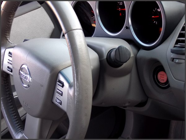
In my 08, I put the heated steering wheel switch to the left of the steering wheel just because it was easier and shorter wire runs. Run a wire from the battery with an waterproof inline fuse holder with a 10a fuse in it. Connect that wire to terminals 1 and 3 on the relay. Run a wire from terminal 5 on the relay to terminal 1 on the clock spring and terminal 5 on the heated steering wheel switch. Run a wire from terminal 2 on the relay to terminal 2 on the switch. This is the switch, relay and clock spring that you need. Notice on the clock spring that it has a little two wire plug. That is what you need. That is the one for the heated steering wheel. Most that you will find listed on ebay do not have that plug.
This will make the job easier. I found one on an Infiniti heated steering wheel. Probably going to be tough to find.
It plugs into the back side of the clock spring.
You will need a tap a fuse with a 10a fuse. Run a wire from it to terminal 1 on the switch.
Run a wire from terminal 2 on the clock spring to ground. Run another wire from terminal 6 on the switch to ground.
Terminals 3 and 4 on the switch are for illumination. You need to tap into wires running to terminals 3 and 4 on TCS switch. You can tap into the illumination wires running to any of the surrounding switches.
I know it shows in the illustration that the heated steering wheel switch is located by the heated seats switches. Location isn’t important. It’s wherever you want to put it.
When looking at steering wheels, this two wire plug is what you are looking for. Red and black are the wire colors. Search for 04-08 Nissan Maxima heated steering wheel.
This how-to is for getting rid of the orange side makers on your 6thgen headlights. Headlights look so much better with clear side markers.
Materials needed :
OEM Headlight
Florescent Light Cover (Home Depot)
Silicone
Sandpaper 60 Grit to 100 Grit
Clamps (2-4)
Pliers
Chisel
Knife or Flathead screwdriver
I took the headlights off and I took the HID ballast and the D2S bulbs out of them and place them away from the heat. I didn’t use an oven instead used a heat gun letting me have more control.
Next when you open the headlight cover there is a screw on the lense take out the black screw and then slowly pull out the chrome piece containing the amber piece. Once done take a knife or a screw driver ( flat head ) and slowly pry out the amber piece the lower part is easier to take out but you have to jiggle out the upper part because is tight.
Take the florescent light cover * under 10 $ from home depot* and using the chisel cut a piece that can be used to trace out the amber piece in which you would replace. Use the chisel to cut the piece of florescent light cover to a smaller size or use a pair of pliers to clamp out the unnecessary pieces that are remaining and close to your out line.
Getting near the outline that you traced? Then is time to start sanding I used 60 grit and then worked with 80 to 120 .. but mostly 60 and here are the end results but close enough keep sanding until is small enough to fit back into the lenses.
Use silicone to glue it on the edges of the chrome piece all you need is to use the tip or something to align it to the edge so that it won’t show the glue . next use clamps to hold it in place and leave it there until it dries. After its dried put back the chrome piece into the lenses and screw it in heat up the oven or use the heat gun to put it back together and then just repeat to the other side.
Put back your D2S bulbs and ballasts all these came off fine for me just with patience and screwdrivers.. All is done take a walk outside and put it back into the car and put it all together and get some stealth bulbs .. I used Sylvanias 1157’s that are clear when off but orange when lit.
I was getting the following code: P0335 Crankshaft Position Sensor A Circuit Malfunction
This code was causing my car to go into “limp mode” and wouldn’t go over 3500 RPM. Also, don’t confuse this sensor with the Camshaft Position Sensor. The sensor is very easy to change. All you need is a 10MM socket.
Symptoms:
Car hesitates to start (or may not start at all)
Engine stalls when it is warmed up
CEL Code: P0335 Crankshaft Position Sensor
The Fix:
I ordered a sensor from eBay which claimed to be OEM. The part number is 23731-AL60C. While the car started up fine, it still wouldn’t rev over 3500 RPM. Likely a faulty sensor. So I went to my local Advanced Auto and purchased a new one. With the discount code, it came out to $35.00. After installing the sensor the car started up perfectly and went out of limp mode. I went for a quick drive and code was permanently gone. I’m always about OEM products when it comes to sensors. However, in the case the aftermarket one below work just fine and comes with warranty. Just ensure you keep the receipt.
5-Speed Auto Crankshaft Position Sensor Location
The crank sensor is located at the bottom center of the engine just below the flywheel area.


")


")


")


")