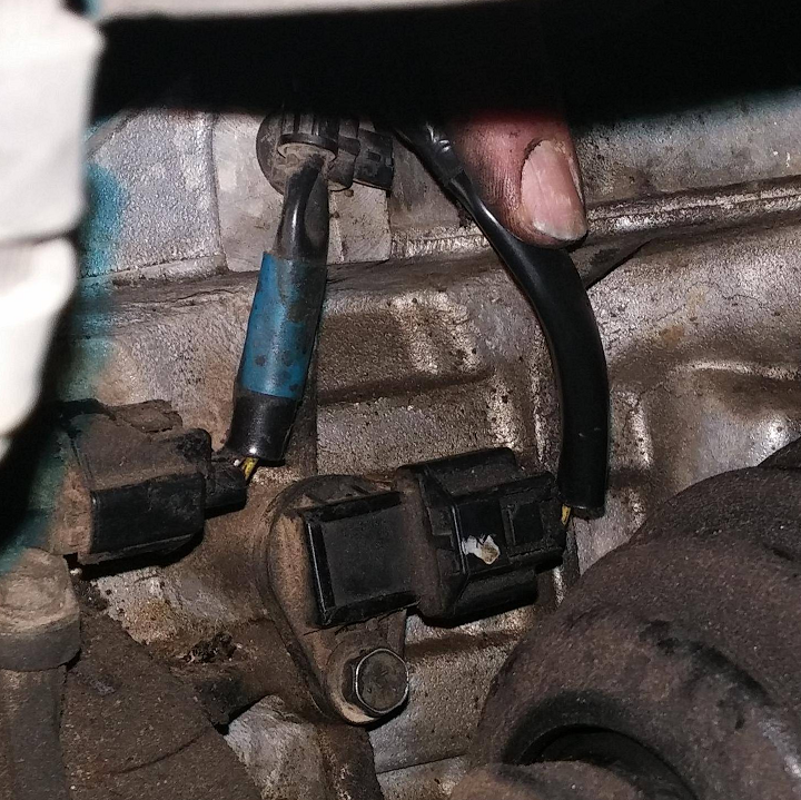
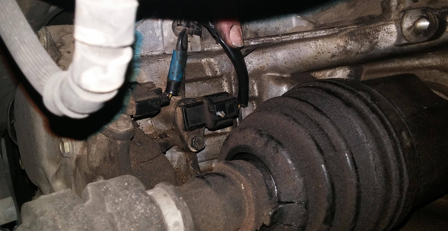
I was getting ready to just buy and replace the sensors. However, I decided to check the harnesses for these two sensors. Surely enough, the harness had an exposed wires due to corrosion and the connectors were very loose. I fixed the exposed connections and tapped up them up nice. I also ensured the harness plugs were properly secured. And PROBLEM resolved for these two codes.
This video shows you how to remove and replace your Crankshaft Pulley. It’s also a good idea to change the Crankshaft seal which is only a few bucks. Crankshaft seals on the VQ are known to leak over time.
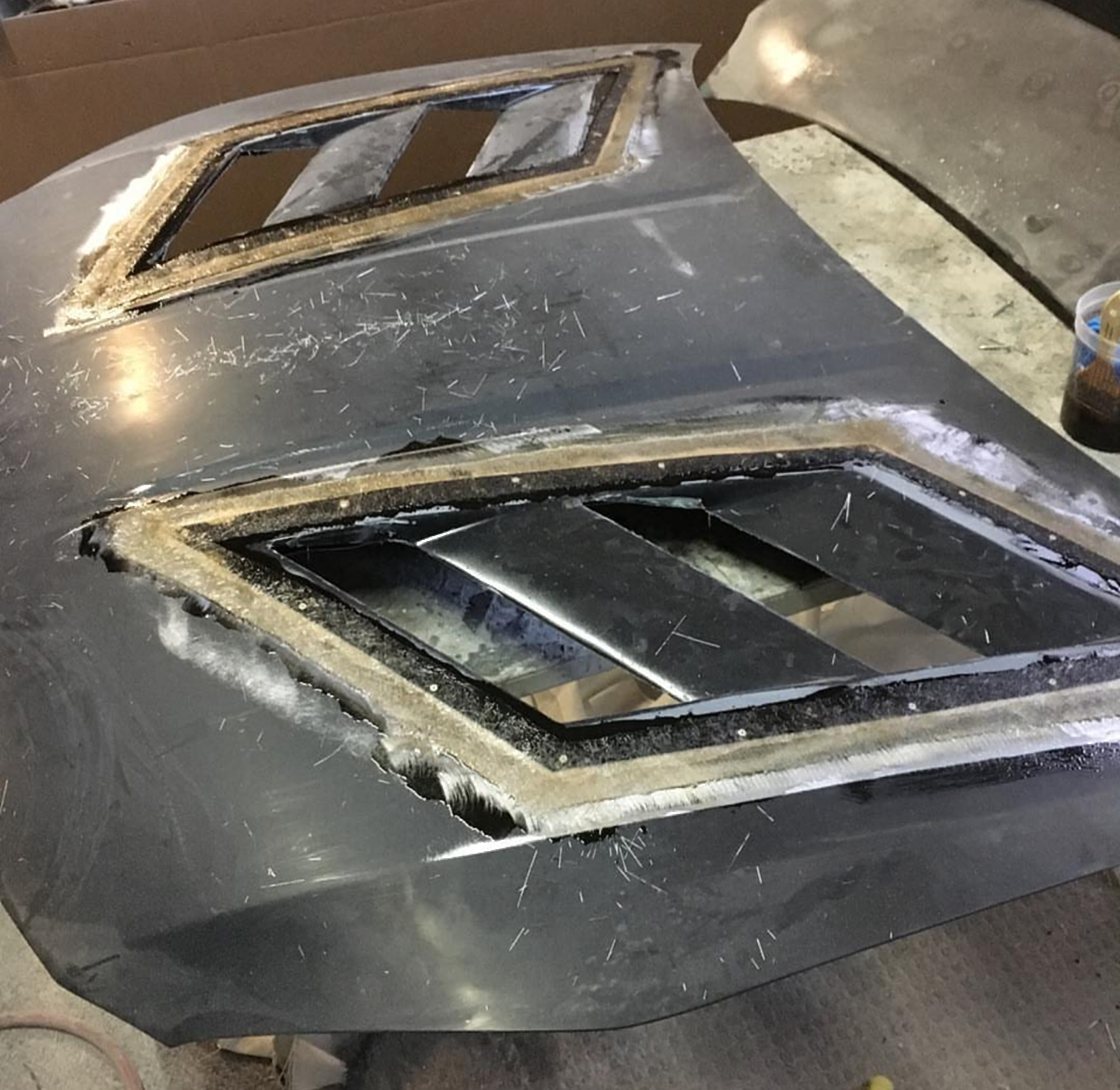
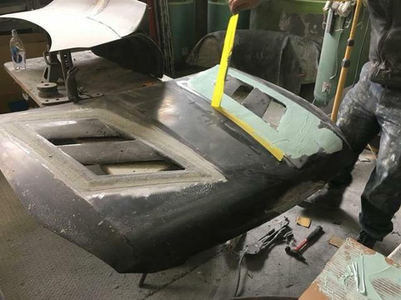
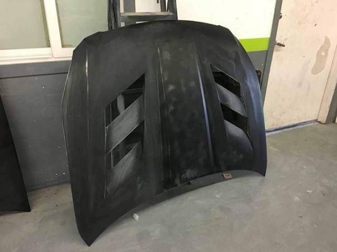
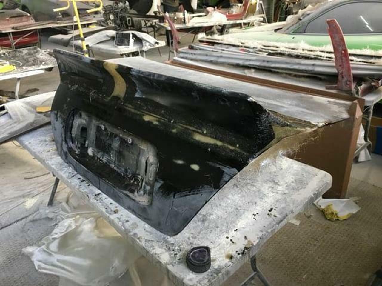
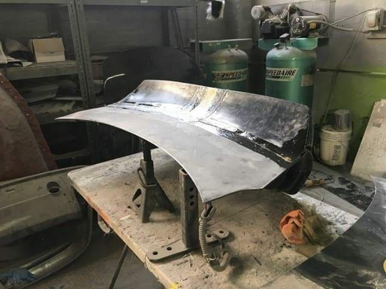
David is currently prepping for car show season and working on some very unique mods. Below is a teaser of the hood and trunk that he is working on. This post will updated with progress and ultimately the final product.
The SSIM (Secret Sauce Intake Manifold) was created years ago by member SR20DEN. This involves cutting the shelf out of the main chamber of the upper intake manifold and removing the VIAS assembly. This will still lose a little low end power, but the gains in the top end are very noticeable. It’s definitely a modification that is worthwhile.
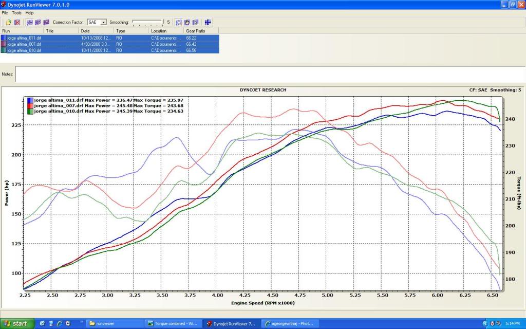
Below are the results of 3 different Intake Manifold setups. All runs done on the same dyno with the same AFR (tuned for 13) and around the same temp. Stock (runfile11), SSIM (runfile10), VIAS delete (runfile7). Your constructive input is welcome but I am not here to argue about any of my results, this is what I did and that is what I got end of story so please no flaming. Enjoy!!!
Stock IM with functional VIAS.
Stock IM with VIAS deleted, NWP Block plate used.
SSIM with VIAS deleted, NWP Block plate used.
All three HP overlay.
All three TQ overlay.
All data combined.
My thoughts on the SSIM vs Stock.
First of all I am suprised that the SSIM did so poorly when compared to both the Stock setup and the VIAS delete.
It posted losses across the board, it only begun to edge out the stock setup after 5600rpm with a gain of 12hp
at 6300rpm.
Against the VIAS delete setup it made the same peak power but posted some gains after 6100rpm, average of 5hp with a peak of 7hp at 6500.
It was totally killed by the Stock setup from 2500rpm until 3800rpm, max of 24tq at 3400rpm. Never made any gains in usable torque.
Killed by the Stock setup for HP as well, losses from 2500rpm until 3900rpm, an average of 10hp with a peak of 16hp at 3500rpm lost to the stock setup.
From 3900 until 5600 they were about the same.
My thoughts on the VIAS delete vs Stock.
3800rpm seems to be the magic number in this comparison. Below 3800 the Stock setup is better but after that its all gains with the NWP Blockplate and the VIAS delete!!!
From 3800 all the way to redline with the VIAS delete I showed an average 8hp gain across the board with a peak of 10.5hp at 6000.
From 2700 until 3800 the Stock setup was good for an average of 8hp over the VIAS delete with a peak of 9hp at 3400.
From 3800 until redline the VIAS delete made an average of 8tq more with a peak of 10.5tq at 4200.
From 2800 until 3800 the Stock setup was good for an average of 10tq more with a peak of 16tq more at 3400.
The verdict….. Its really just up to what you want to drive with, I am choosing the NWP Block plate with an unmodifed IM for now.
I like the power from 3800rpm until redline rather than power below 3800rpm, I feel the losses down that low are worth the gains I see up high. When I stomp on the gas I dont stay below 3800 for very long, this makes the VIAS delete a beneficial mod IMHO.
The gains from the SSIM is irrelevant since it only starts to make HP after 6100rpm and totally destroyed all low end torque. Since I run out of engine the SSIM may be a viable option with a TS ECU and a higher redline, timing etc, etc.
This is a gallery of Secret Sauce Intake Manifold (SSIM) Setups. The SSIM (Secret Sauce Intake Manifold) was created years ago by member SR20DEN. This involves cutting the shelf out of the main chamber of the upper intake manifold and removing the VIAS assembly. This will still lose a little low end power, but the gains in the top end are very noticeable. It’s definitely a modification that is worthwhile.
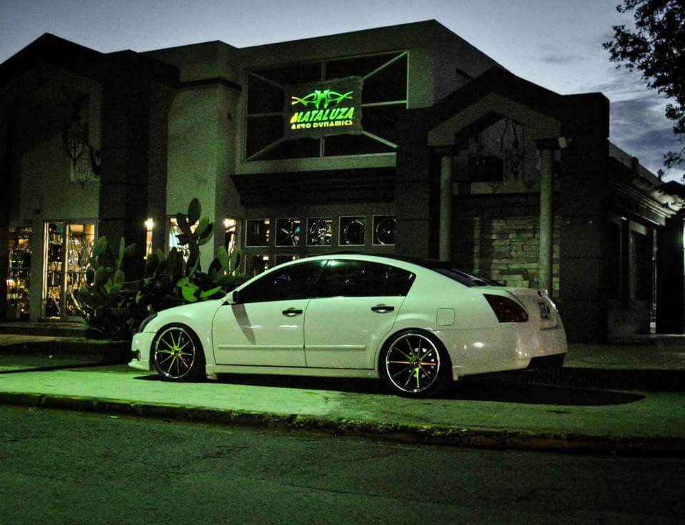
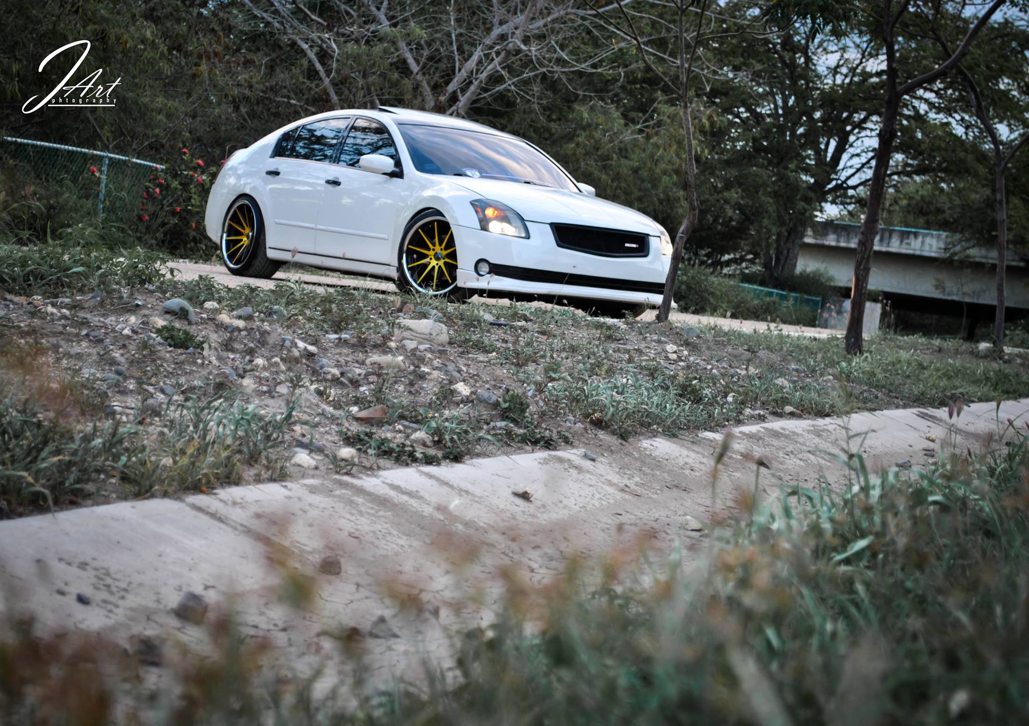
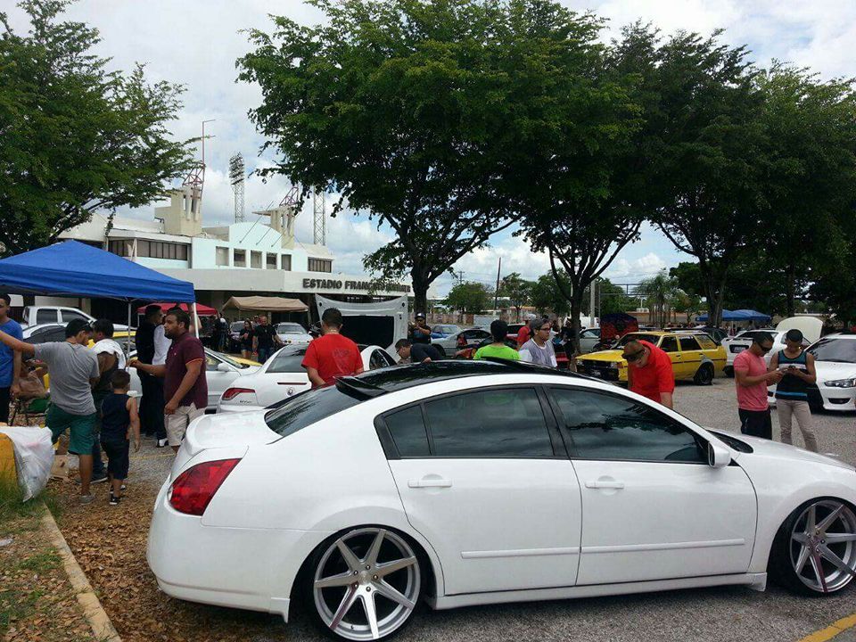
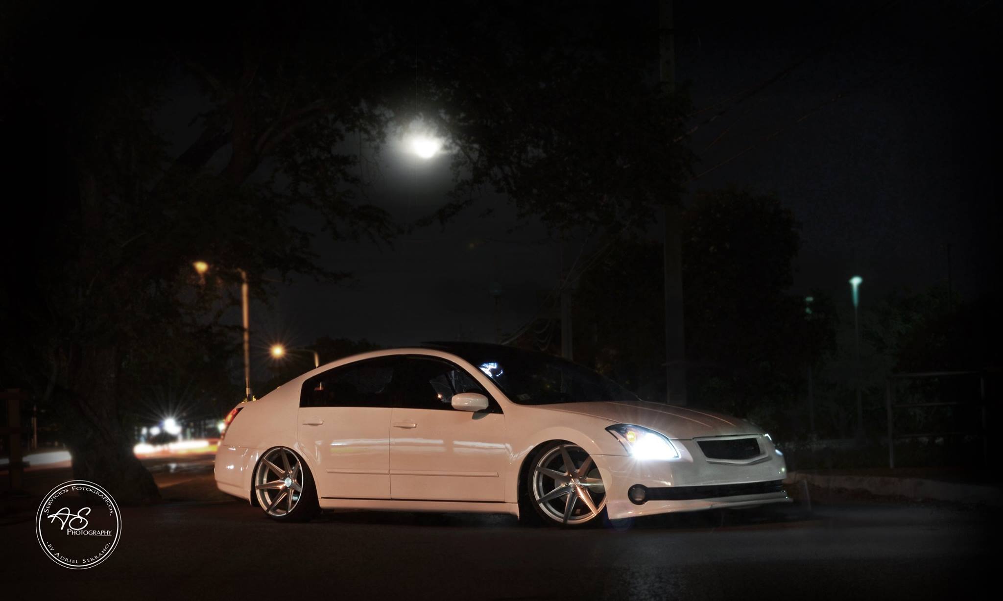
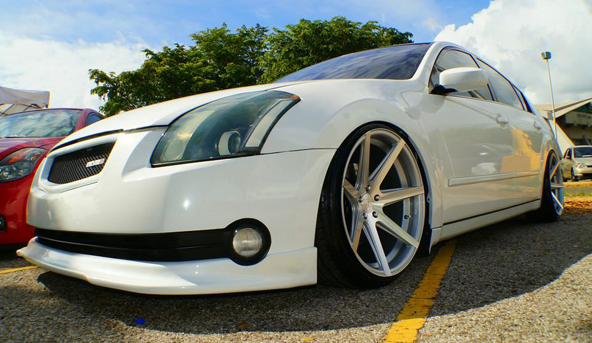
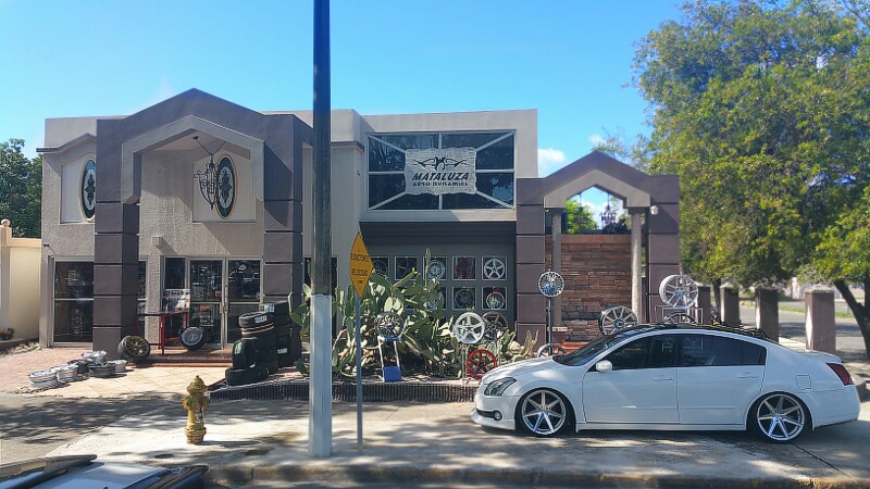
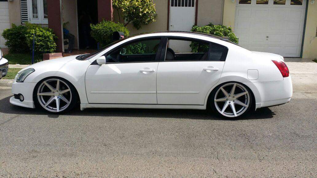
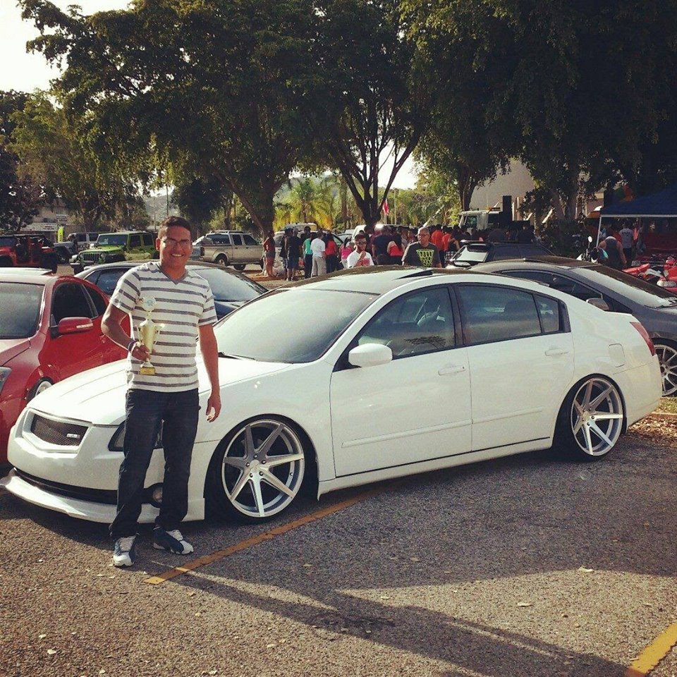
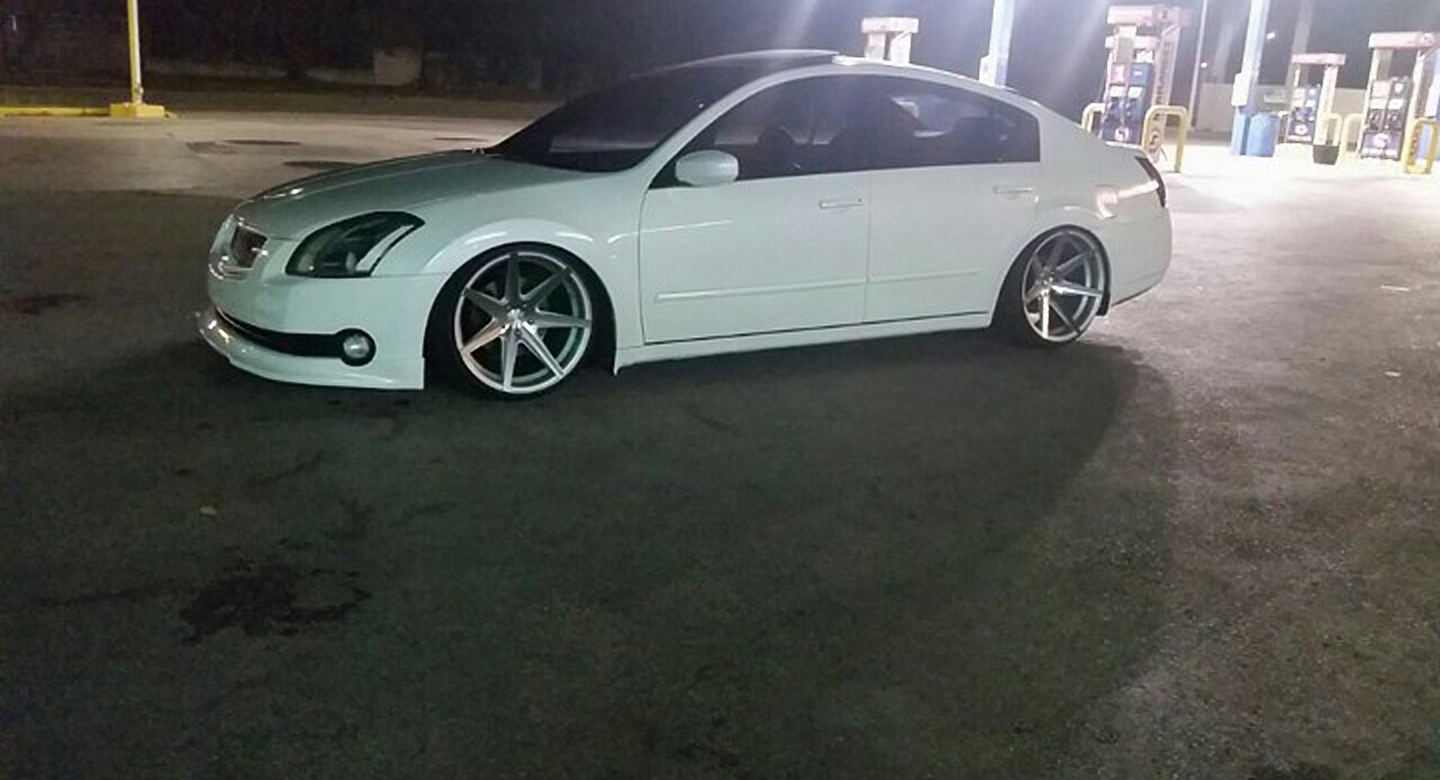
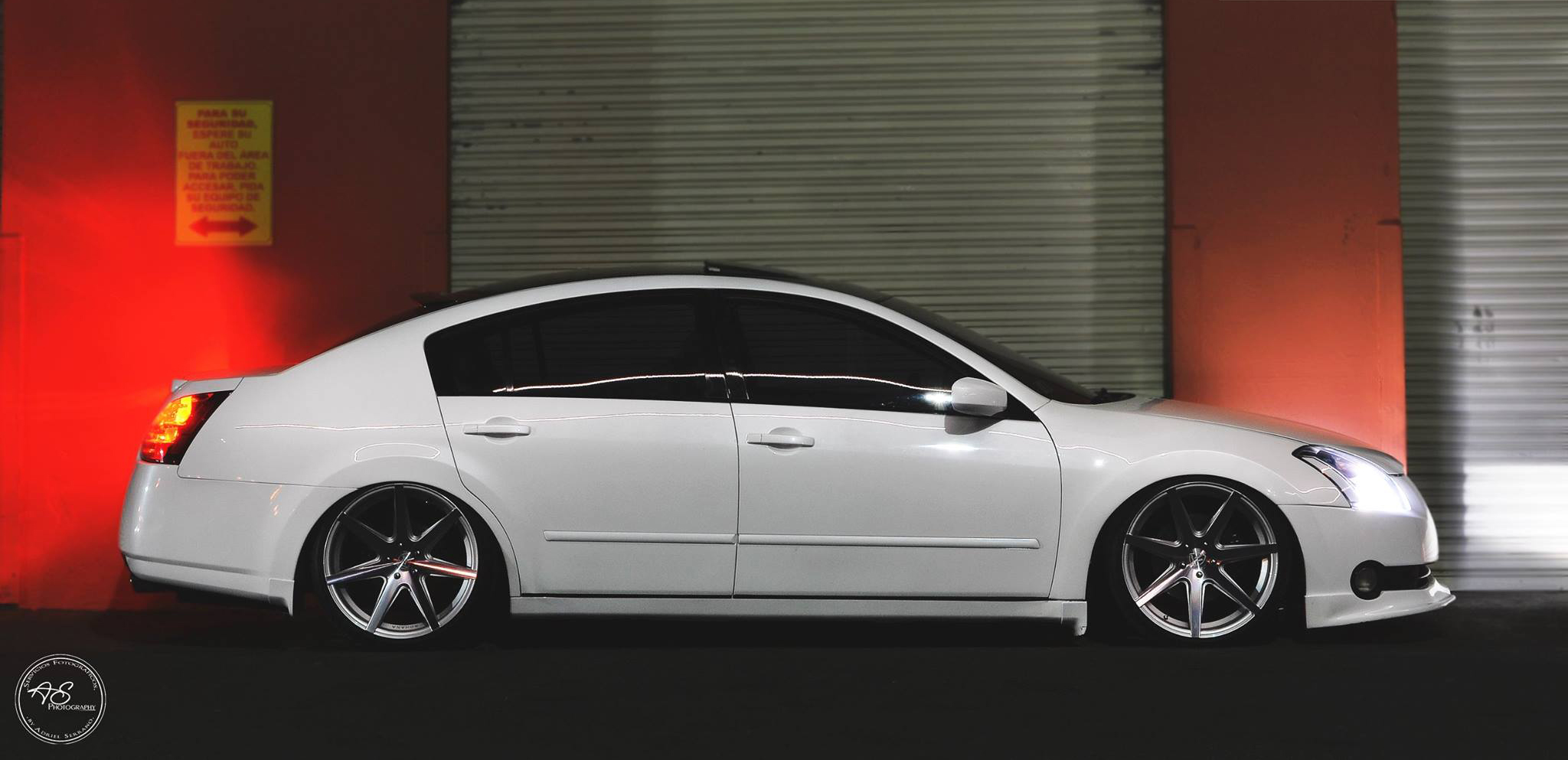
Year: 2005 Model: Maxima Color: Custom Lexus IS-F White Transmission: Manual 6-Speed Trim: SE
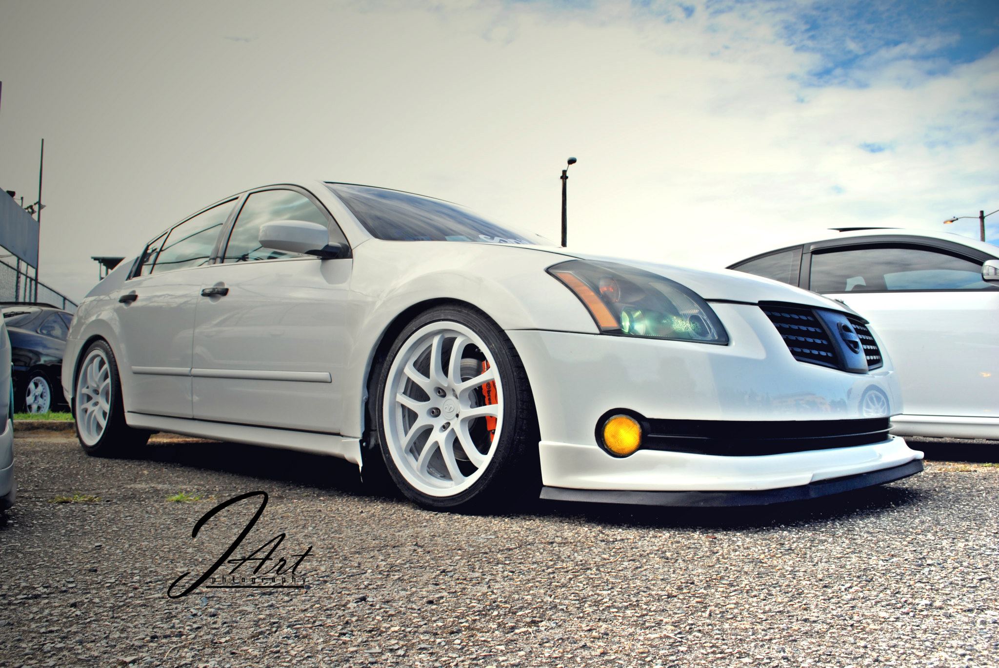
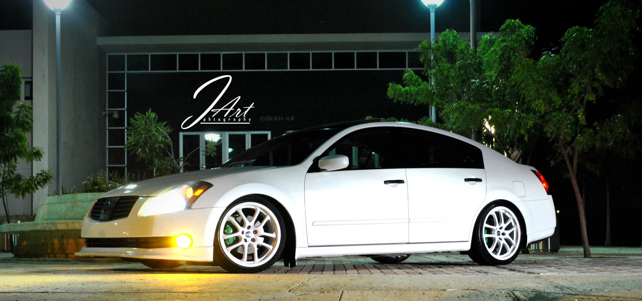
This is Richard’s 2004 Nissan Maxima. He lives in Ponce, Puerto Rico. His 6thgen has come a long way and continues to look better and better! More progress and updates to come. Awesome work.
This 2007 Nissan Maxima came in with the complaint that the gas gauge was stuck on empty. Actually a closer look revealed that the gauge needle was stuck under the empty stop peg. Due to the coloring of the instrument cluster lens I was unable to get a picture of this before disassembly.
If you have a strong magnet you can use it to move the gas gauge needle into the correct position. If you do not have strong magnet or if you just need to know how to remove the instrument cluster, continue reading.
The top cover over the instrument cluster assembly is held in place by spring clips as shown in the next picture. To unfasten the cover lift up to release the clips. Note that there is a tether cable that attaches the cover to the dash carrier. It does not need to be removed. In fact I do not even know if it can be without damaging something.
There is one phillips headed screw behind the middle of the assembly that needs to be removed.
I was also hoping that the other two phillips screws were all that was left to remove the instrument cluster. They do have to come out for the final disassembly to correct the needle issue but not now.
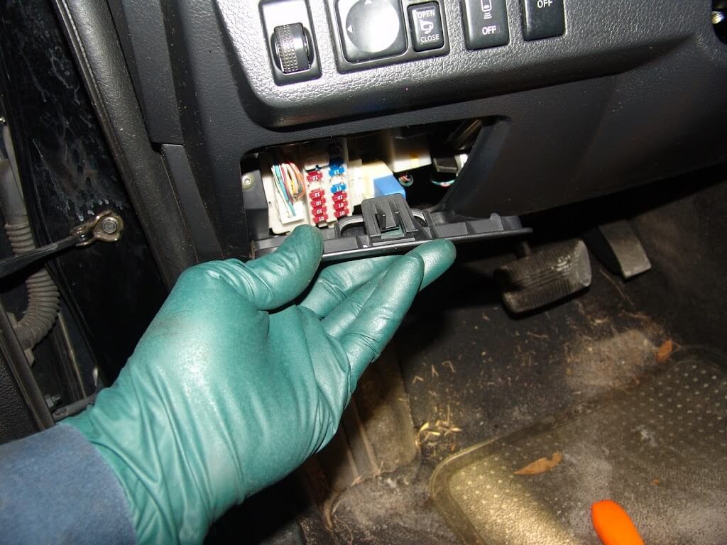
I could feel something holding the bottom of the instrument cluster so I wanted to remove the covers under the steering column. Removing the fuse box cover reveals ons crew to the left.
It has a torx head. There is also one other matching screw under the right side of the panel.
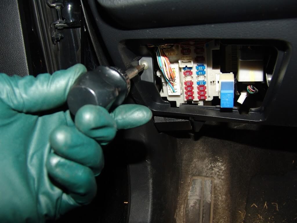
I am not sure if the inner steel panel actually has to be removed but it is only two screws and it made it much easier to take some of the following pictures.
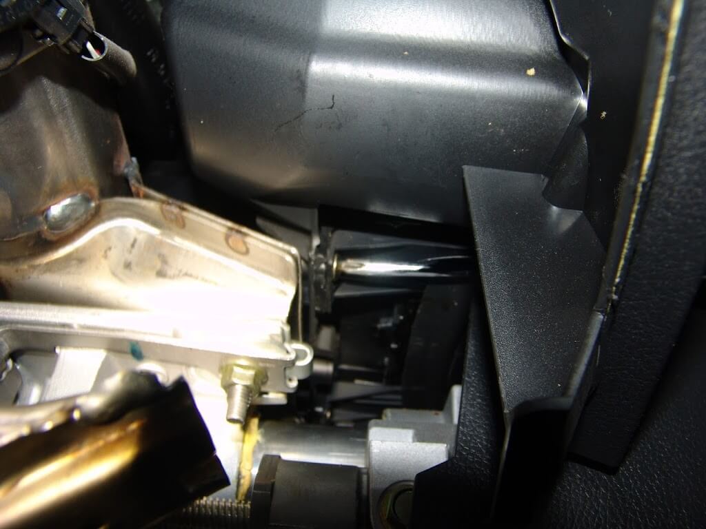
To remove the two lower retaining screws I used a long phillips head screwdriver and magnetised the tip. Also I extended the steering column all of the way out towards the driver’s seat and then fully down.
Looking under the dash I could see where to move the tip of the screwdriver to align it with the screw.
The one on the right is a little bit more difficult to locate and remove. In fact I had to get my longest phillips screwdriver out to do this efficiently. For reassembly I inserted the screwdriver on the left side of the column and attached the screw to the magnetic tip, then carefully slid it to the right to align it with the mounting hole. I know this takes a few special tools and is somewhat tedious but it beats having to drop the steering column and possibly more.
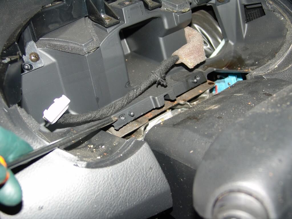
There is one harness connector to remove. The harness also is attached to the cluster by clip shown in the center of the next picture. I am pointing to the left lower mounting screw hole with my screwdriver.
There are a series of plastic clips all of the way around the instrument cluster assembly that have to be dislodged. Also the two screws mentioned earlier.
With the cover removed it is easy to see that the needle is on the wrong side of the stop peg.
A simple little flip with my screwdriver…
…and the needle is back in it’s correct location.
If you want to avoid this problem altogether, never disconnect and reconnect the battery connections with the ignition switched on.
This document has been composed with the online instant web content editor which can be found at htmleditor.tools


")


 Setups")