Member Credit: EddyMaxx (Additional photos/info by chrisaust and CleanMaxx)
Are you looking to get rid of that orange cluster on your 2004-2006 Nissan Maxima? Well you can install an 07-08 cluster very easily as everything is plug-n-play. All you need to do is purchase a cluster with miles closest to your car and cluster cover/hood. The 07-08 cluster will also work on 04-06 6-Speed 6thgens (even if you are HR swapped lol).
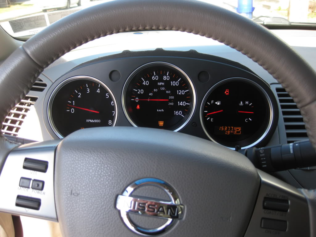
Below is a photo of the 04-06 OEM cluster (all orange….yikes). The only members I’ve seen that like the orange are the ones with the peanut butter elite orange Interior (only because it matches the theme of the car). You can also add custom LEDs to your existing 04-06 cluster but most members just want a newer and refreshed look.
The first step is to buy a speedometer/cluster from eBay or local junkyard (or Facebook Classifieds). Try to get one as closest to your current mileage. You can also pay for an odometer adjustment but just easier to get a closer one to your actual mileage.
The pricing for the cluster is anywhere between $60 and $120 depending on where you get it from. Make sure to also buy the cluster cover/hood as well. Some people forget about this. The cover is usually around $40-50 bucks.
The whole swap takes about 45 minutes to an hour.
You will also need the following tools:
Phillips screwdriver
Flat-head screwdriver (or preferably something thin and plastic)
Socket wrench only if you need to disconnect battery to work on electrical system (not really required)
Something to cut plastic (for creating hole to route cluster plug/harness)
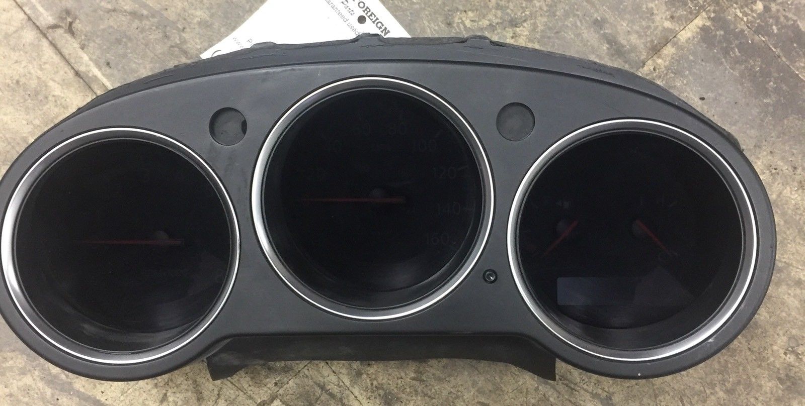
Photo of the Purchased Cluster/Speedometer (Miles were very close)
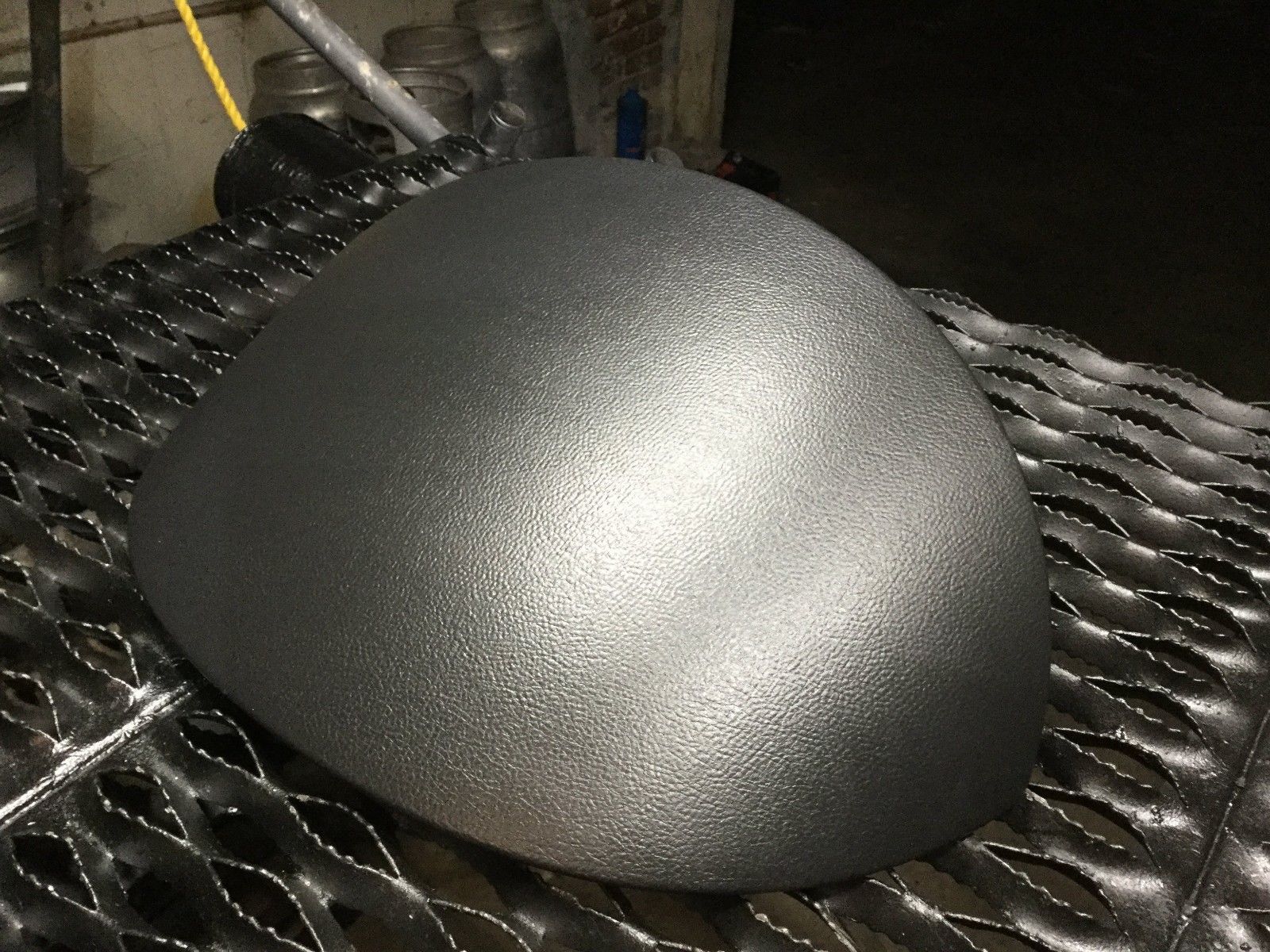
Photos of Cluster Cover/Hood
Steps to remove the old cluster and add new cluster
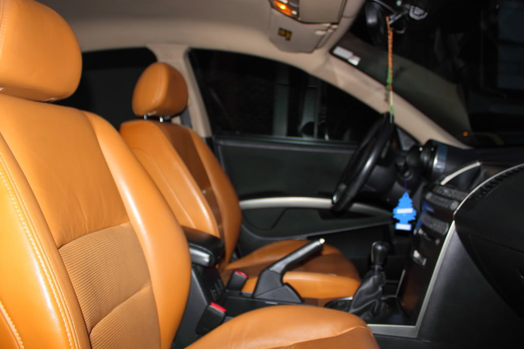
Underneath the steering wheel there are 3 screw holes… Remove these screws with Phillips screwdriver. Adjust the steering wheel all the way out and down. Inserting flat-head screwdriver in between two plastic pieces on the right side of the steering wheel where the windshield wiper knob is. Carefully pop apart plastic housing surrounding steering wheel and set aside. Remove plastic covering over gauges. Using flat-head screwdriver or thin plastic, slide under top middle plastic piece and slowly lift up to pop out. Then slide under each piece on left and right, pop out front part first, then lift and pull towards you. On top of gauge cluster is one single screw, remove this: Under gauge cluster are two hidden screws, unscrew both but don’t remove, it’s easier to pull out gauge cluster and screws will come out with it, then you can take them out.
Mount new cluster on the dashboard.
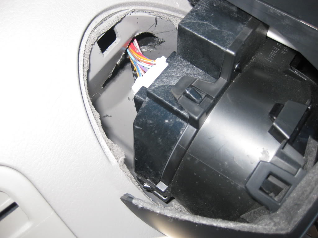
You will notice that the speedometer plug is on the opposite now. Since the plug is short, you will need to cut a hole and route the plug over to the left side. You can also stretch the harness if you don’t want to cut a hole. Just very careful.
Cutting the hole out will make it easier for you to route the plug into the new cluster. Simple and EASY!
Follow the reverse steps of removing the cluster and add back all the screws. Put the cover/hood back. Start the car and you are all SET! Enjoy your new cluster.
Below is an example of the final product. The clusters below have modded LEDs which you can also add.
This installation process is for a set of Eibach Suspension Springs Pro Kit 6369.140 with 2.0″ drop in front & 0.8″ drop in rear.
REAR END: 20-30 minutes
Tools Needed: Air rachet or air gun, 18mm socket 3/4″ open wrench & adjustable floor jack
These instructions are bases on having a hydraulic lift
Loosen lug nuts
Raise car
Take tires off
Place adjustable floor jack just under the lower control arm to where it rests with just a little pressure to keep it inplace
Remove nut & bolt
Lower floor jack until completely out of the way (The spring will NOT shoot out as you lower jack)
Push down on lower control arm & remove the OE spring
Use the OE “lower” bushing with new Eibach spring
Install new spring with lower OE bushing ensuring you line up the bottom of the spring with the ‘stop’ in the lower control arm.
Raise arm back into place
Put nut & bolt back in place
Once back in place & secured, remove floor jack & proceed to other side.
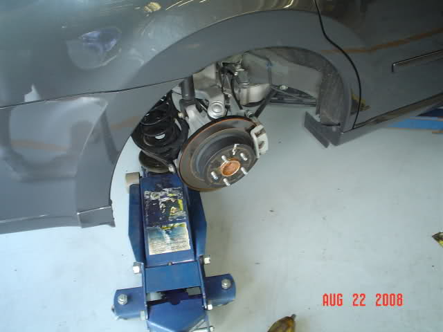
FRONT END: 2-3 hours depending on experience
TOOLS NEEDED: Air ratchet or air gun, 17mm socket, 3/4″ open wrench
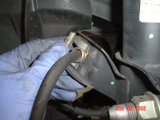
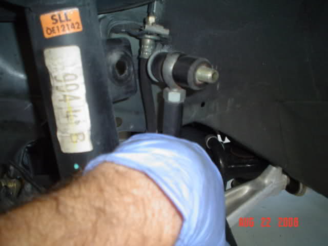
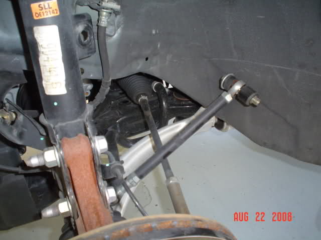
You have 2 bolts that hold the brake in, 1 bolt for your upper control arm, your brake hose ‘clip’ & 2 small rubber grommets
Remove all of these parts (bolts, nuts, grommets, etc)
Then go into the engine bay & remove the 3 bolts (14mm I think) that hold your strut in place. If you have a FSTB, you’ll have to remove this also. Do one side at a time!
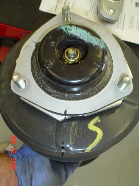
6. Remember how your strut arm looks when you pull it out. It’s best to mark each item with a straight line using a permanent marker as shown below after you remove it.
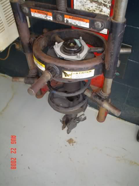
7. Now take it to the spring compressor & compress the spring.
8. Tighten the spring down in the compressor, unbolt the top bolt & remove everything.
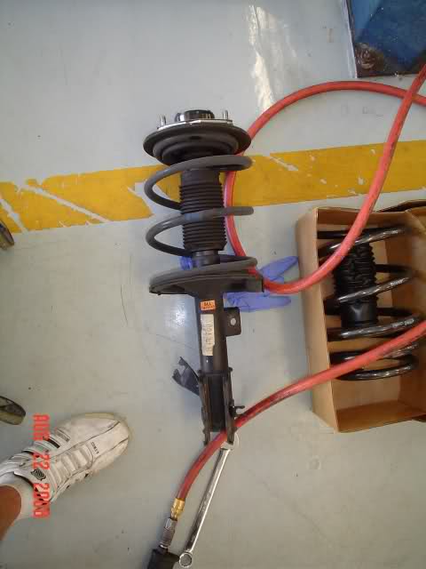
9. Be sure you install the new bushing and dust cover before you compress the spring back together.
10. Line up the new springs in the coil & compress it just enough to place the bolt back on.
Before:
After:
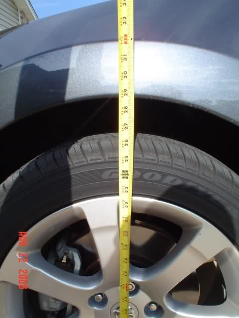
11. Before front drop: 29″
12. After front drop: 27″
13. Before rear drop: 27 5/8″
14. After rear drop: 27″
Instructions on how to replace stock taillight bulbs with LED’s (or can be followed for regular bulb replacement)
Parts
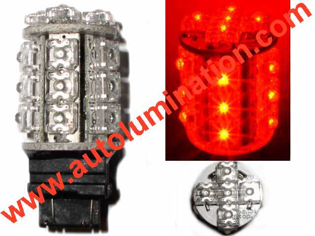
I bought these particular bulbs from autolumination.com(link is external) it’s the Light Tower II. I’ve tried out many different bulbs and these finally work.
20 Powerful Wide Angle Oval LEDS
15 side facing LEDS
5 forward facing LEDS
We require the 3157 bulb (not 1157) So you’ll need 4 3157 Red for the rear (dual circuit, parking light/blinker or brake)
The front Ambers are 1157 (socket type not wedge type)
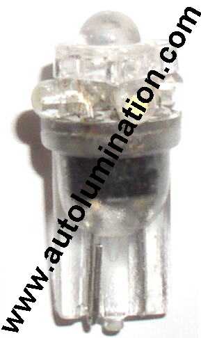
Here’s the bulbs I used for the rear side marker lights
(I also used these for the reverse, foot wells, license plate and stock alarm light)
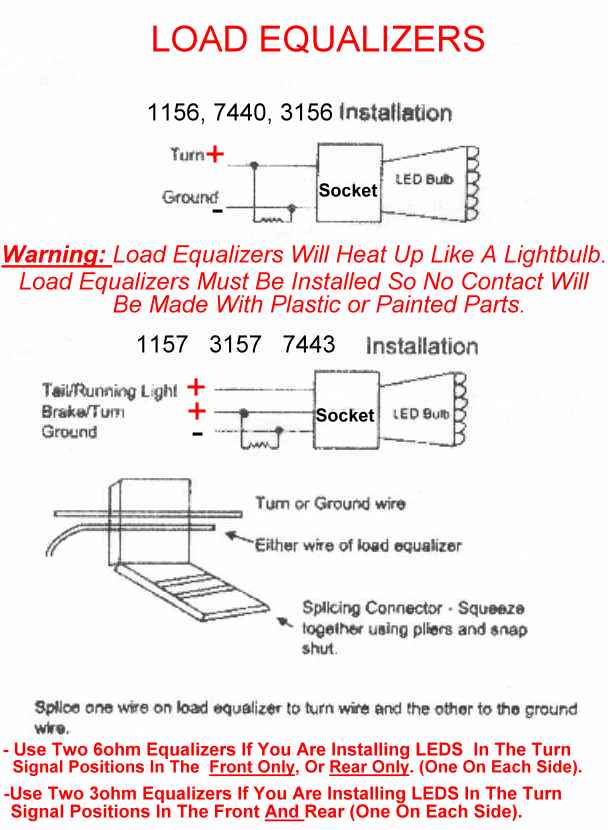
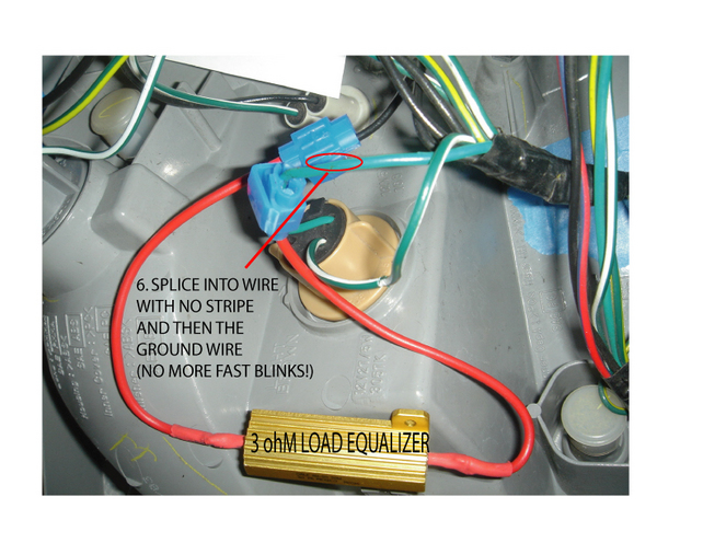
I also ordered 2 3ohm (One on each side covers front and rear) load equalizers as well because I have the fast blinking dilemma you get with LED’s. The load resistor simulates the resistance of the incandescent bulb and restores the turn signal to normal operating function with the led. Here’s the diagram to install these:
Install
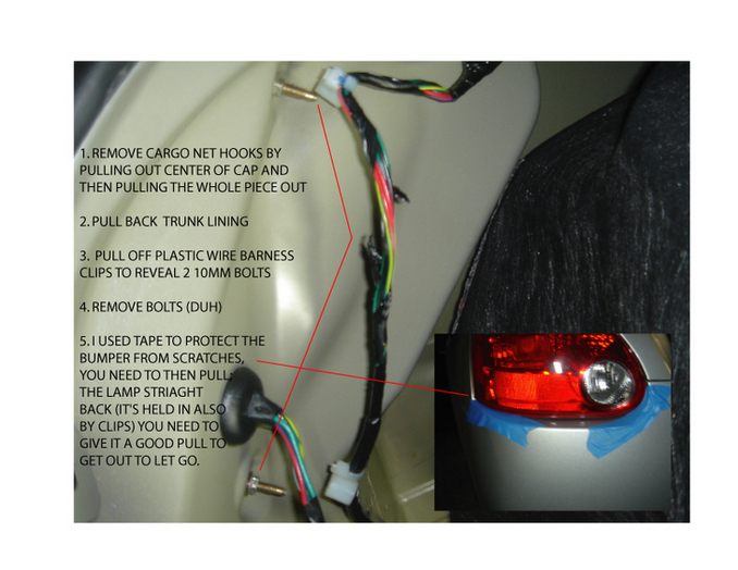
Note: When removing the taillight assembly, you do NOT just pull out the red glass.
The painted frame portion between the glass and trunk lid is a part of the taillight assembly..
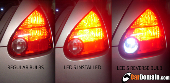
Before and after pics:
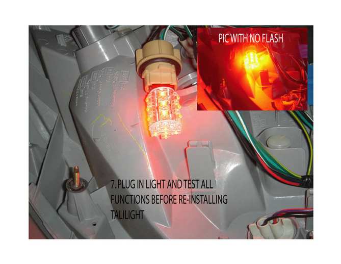
As you can see they are much brighter than the stock bulbs and the color in person is a way deeper red than stock. I also replaced the reverse bulbs and side marker bulbs with LED’s.. looks sweet So my entire rear housing is LED I used the matrix LED’s from autolumination.
Why is it important to have wheels properly torqued?
Overtorquing wheels can damage alloy wheels, snap lugs, and can also make it very difficult to remove a wheel with the standard Maxima tire wrench should you have a flat in the middle of the night in the middle of nowhere.
Unevenly torqued wheels can easily result in damage to brake rotors. Undertorqued wheels can result in your having to pay for the cow killed by your wheel as it zips across the meadow.
WHEN?
As soon as convenient after taking delivery of your Maxima, and after every instance when anyone has removed any wheel for whatever purpose (such as tire rotation or brake work/adjustment). Nissan also recommends that the wheels on a new Maxima should be retorqued at around 600 miles. If you did not do this, but the wheels have not yet been off your Maxima, please consider doing it soon..
AMOUNT?
As folks who work on your car are generally only concerned with making sure your wheels don’t fall off, the universal trend is to overtorque. Partially in view of the same concern, manufacturers tend to overstate the amount of torque needed for cars. Here is an example: 70 foot pounds of torque would easily be sufficient for the 6th gen Maxima. ‘Erring’ on the cautious side, Nissan recommends 80 foot pounds. My ’04 SL was actually delivered with from 87 to 96 foot pounds on every lug nut.
I have kept my wheels torqued at 75 foot pounds for over a decade. My son has used 70 foot pounds on all his vehicles for almost twenty years. Less venturesome souls should still torque to no more than Nissan specs (80 foot pounds).
WHICH TORQUE WRENCH?
Ignore the ‘flex’ wrenches; they are not accurate. Stick to ratchet (click) wrenches. Ignore the ‘inch pound’ wrenches; they are not for wheels. Stick with ‘foot pound’ wrenches. It may be possible to torque Maxima wheels with a 3/8″ drive torque wrench, but I would never torque wheels with anything but a 1/2″ drive wrench.
Torque wrenches are sensitive instruments, and should not be abused. They are one of the few tools Craftsman will not back with a lifetime warranty; they cover them for only one year. But with proper care, and an occasional recalibration, they should last decades.
I use Craftsman (Sears), but others such as Kobalt (Lowes) and Rigid/Husky (Home Depot) are probably comparable. Expect to pay from $60 to $80 for a top grade wrench, unless you have a coupon or hit a sale.
SETTING THE TORQUE WRENCH
Read the directions accompanying the wrench very carefully. Not all wrenches are alike. One common setting method is to twist the grip until the cursor is on the ‘tens’ marker (such as 70 or 80 or 90) at or below your desired setting. Then twist the ‘fine selector’ collar until the exact pound you want is centered on the scale.
For 75 foot pounds, we turn the grip until the cursor reaches 70, then turn the ‘fine selector’ collar until its cursor reads 5.
For 80 foot pounds, we turn the grip until the cursor reaches 80, then set the ‘fine selector’ collar to 0.
Once we have the desired foot pounds set, we must turn the ‘locking collar’, else the setting will not hold during use of the wrench.
SOCKET?
Use ONLY DEEP SET (LONG) socket, otherwise an extension is needed. Unless you are fumbling with a 3/8″ drive torque wrench (a no-no), the socket must be 1/2″ drive. The OEM lug nuts on ALL 6th gen Maximas are 13/16ths”. Although a 6 point socket (6 coves inside opening) is preferable for wheel work, most deep set sockets come with 12 points, and these work fine for torqueing.
Many Nissan dealers put one locking lug nut on each wheel. For reasons that escape me, the coded socket furnished to turn these locking lug nuts has a drive end that requires a socket slightly larger than the 13/16th” of the regular lug nuts. I bypass this problem by using a 21mm deep set metric socket, which works well with both the 13/16ths lug nuts and the drive of the locking lug nut socket. If we carefully measure the tire tool that comes with the Maxima, we find it is actually 21mm, not 13/16th”. Just another Nissan quirk . . .
TORQUEING WHILE MOUNTING WHEELS
Mount wheel onto hub. Hand-tighten all lug nuts. Use Maxima OEM tire wrench (the torque wrench may also be used for this) to VERY LIGHTLY snug the lug nuts.
Lower the car until the tire has good contact with the ground/floor. Torque each lug nut to specs (Nissan says 80 foot pounds, I use 75). IT IS IMPORTANT (for the wheel, rotor, etc) to torque the lug nuts in one of these two ‘across-the-hub’ orders: 1-3-5-2-4 or 1-4-2-5-3. Either of these orders may be used in either a clockwise or counterclockwise direction. In order to keep things simple, I always consider the lug nut nearest the valve stem as #1, and number clockwise.
When using the torque wrench, apply a steady pressure, using only the grip, and being alert for the ‘click’ and sudden slight slippage that tells us the appropriate torque has been reached. Release pressure on the wrench immediately, as further pressure takes the torque past the desired setting. Never slip a pipe or other ‘extender’ over the handle to ‘make things easier’.
Starting the torquing with the handle at the ‘4 oclock’ position works best for me. That enables the pressure to be applied in a natural downward direction, and reduces chances of damage to the car if anything slips.
ADJUSTING TORQUE FOR WHEELS ALREADY MOUNTED
Read the last two paragraphs in the preceeding proceedure (Torqueing While Mounting Wheels). Car should be setting on ground/floor, which does not have to be level. Using the Maxima OEM tire tool (or other suitable wrench or breaker bar), loosen a lug nut slightly. Torque that nut to the desired foot pound setting. Proceed to the next lug nut.
In this procedure, it is not necessary to follow the ‘across-the-hub’ torqueing order given above for mounting wheels, although I still use it from habit.
Decided to take pictures as I changed the ATF in my 2005 Nissan Altima SE-R (Should be similar for 6th gen Maximas) since I couldn’t really find any how to’s prior to attempting my first ATF change using the Drain and Refill method. Usually people do 3 drain and refills with a short drive inbetween each making sure to engage in every gear. Some signs that an ATF Drain and refill is needed: harsh shifts, black ATF on dipstick, ATF smells burnt, metal shavings on drain plug, 30k miles.
First off, Nissan recommends Matic K automatic transmission fluid from Nissan. Cost me $10.82 a quart. Ranged up to $20.xx around my area. Anyone worried about attempting this themselves, with little or no mechanical experience, if you can change your own engine oil, you’ll be fine. I actually think its easier then changing engine oil. I would rate it at a 2/10 with 10 being the hardest. Lets begin.
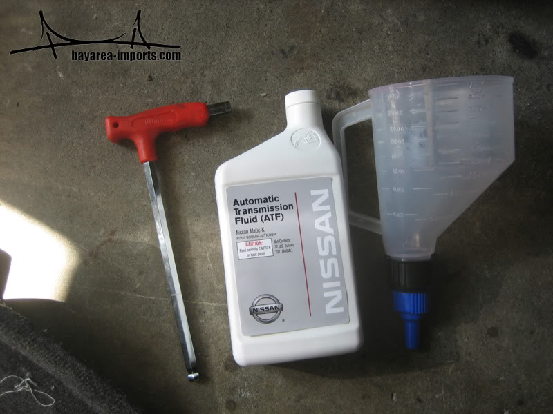
Tools I used: 10mm Hex, Funnel (the one I used has open/close option) and ATF Matic K for 5AT:
Drain plug is located right next to the front electric motor mount. Drivers side, facing the front of the car:
Jack up the car safely and locate the drain plug:
Take off the drain plug and let the fluid drain until it stops. Anything from 2-5 quarts can come out at one time. The rest stays in the torque converter (My old ATF wasn’t that black, it was actually still pretty red, I had left over engine oil in the tub):
Put the drain plug back on and locate the dipstick. Take dipstick out and put funnel in the opening. This is where the ATF will be poured in:
Pour new Matic K ATF fluid into funnel (Looks almost like syrup for Italian Icees but smells nothing like it ):
Pour the same amount of ATF in as you took out. I poured the old ATF into empty quart size bottles to make sure its correct.
Now you’re done with your first ATF Drain and Refill. Go for a short drive making sure to engage in every gear :shift:. I noticed smoother and crisp shifts. My brother said he couldn’t even feel 1st-2nd which was the worst before.
It is common practice to drain and refill 3 times to get majority of the old fluid out. I only did it 2 times as my old fluid didn’t seem that bad, and I didn’t find any metal shavings on the drain plug.
Enjoy smooth shifts from now on…
I want to add that this is my FIRST time doing ATF drain and refill. The above may not be the best or fastest way, but it was the way that I did it. If there are any tips or advance that can be added to this, please feel free.
Prevent heat from transferring from your heads to intake manifold and throttle body! Improve Airflow by eliminating the need for intake gaskets. Each spacer is CNC Machined to the highest tolerances to ensure the best airflow possible. All NWP spacers are port matched to your stock intake ports. A smooth transition from one manifold to another is very important for optimal airflow.
Don’t be fooled by other spacers and thermal gaskets that aren’t properly matched to your intake ports! Never have to replace your intake gaskets again! These intake spacers will last for life and do not require improperly sized OEM intake gaskets! Experience an intake manifold that’s cool to the touch! Experience a better quality product with NWP!
All of our performance parts are made in the USA!
Price: $225
Includes:
– Two 1/16″ High Quality CNC Machined Phenolic Intake Manifold Spacers (Lower Intake Manifold)
– 1/4″ High Quality CNC Machined Phenolic Intake Manifold Lower Collector Spacer (Upper Intake Manifold)
– 1/4″ High Quality CNC Machined Phenolic Intake Manifold Upper Collector Spacer (Elbow)
– 1/4″ High Quality CNC Machined Phenolic Throttle Actuator Spacer (Throttle Body)
– Intake Manifold Upper Collector Coolant Bypass Fitting
– 4 Lengthened Zinc Plated Grade 8 Throttle Body bolts and washers
– 4 Lengthened Zinc Plated Grade 8 Elbow bolts and washers
– 3 Lengthened Zinc Plated Grade 8 Upper Intake Manifold bolts and washers
– 2 Lengthened Zinc Plated Grade 8 Upper Intake Manifold offset studs
– Printed Detailed Installation Instructions with Photos(Click link to download .PDF)
– Two Die Cut Silver Vinyl NWP Engineering Decals
You can start this project from any part you wish, so you do not have to follow the order I did things. I started in the front, and worked my way to the rear of the car for the most part, although you do have to jump around when you get close to the end.
AS WITH EVERY JOB YOU DO THAT REQUIRES UNPLUGGING ANYTHING ELECTRICAL, DISCONNECT THE NEGATIVE BATTERY TERMINAL BEFORE YOU BEGIN!
Tools Needed:
– Phillips Head Screw Driver
– Flat Head Screw Driver
– Panel Popper Tool
– Small Pick-Tool Set
– ¼” Ratchet
– 10mm Socket
– 12mm Socket
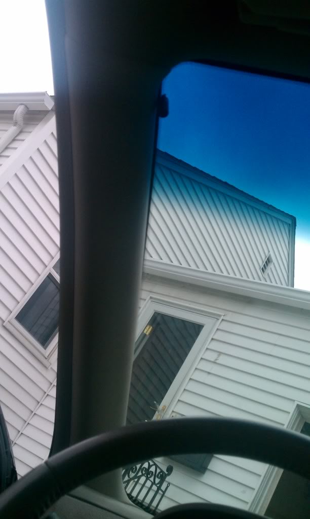
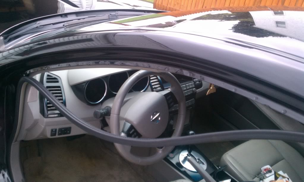
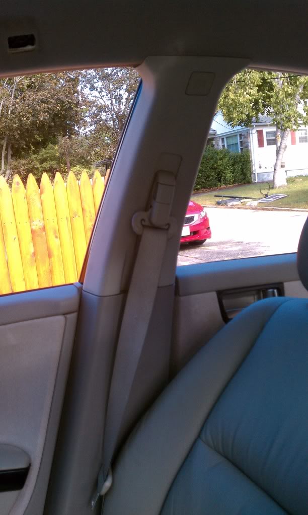
First, I did the A-Pillars:
Start by pulling back the rubber molding inside the door jam, giving you better access to the door side of the pillar.
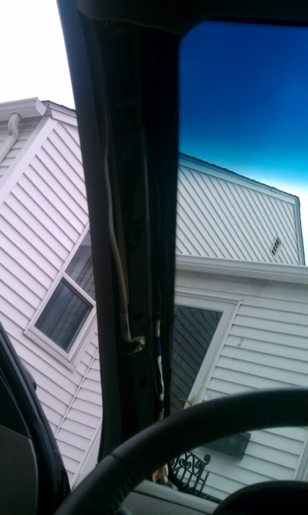
Next, use the panel popper tool to pop the clips out on the pillar, starting at the top, working your way down towards the dash. Start from the outside, then the inside directly across, until you have popped all of the clips out. Once you have all of the clips popped out, you will have to sort of wiggle the bottom out from behind the dash. Repeat for the other side.
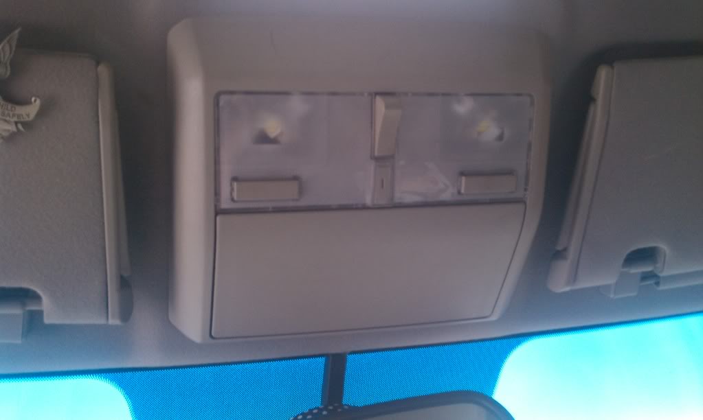
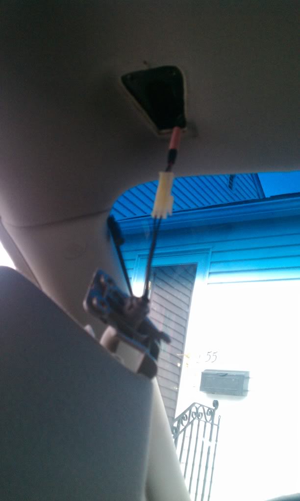
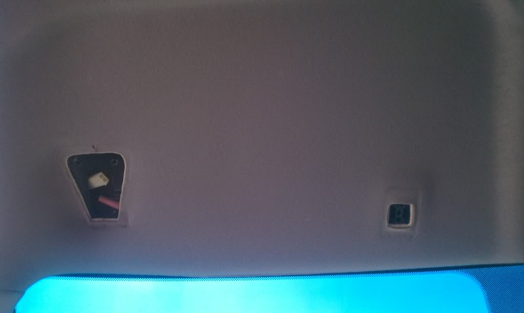
Second, The Dome Light/Sunglass Holder:
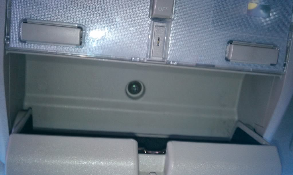
Start by opening the sunglass case, revealing the Phillips head screw holding it to the roof.
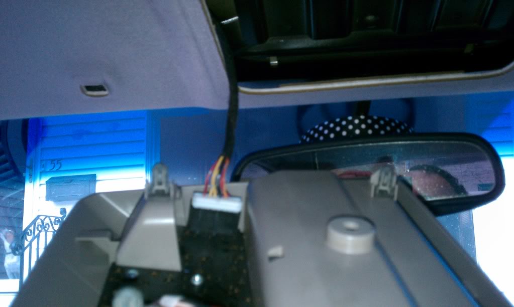
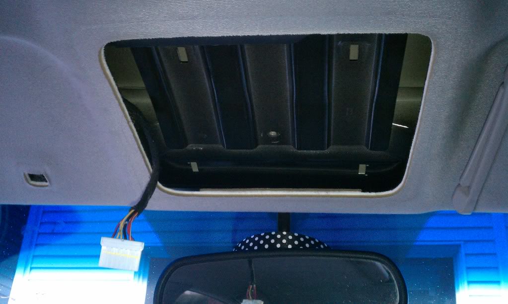
Remove that screw with your Phillips head. Once the screw is out, start pulling down the piece one corner at a time. It will take some decent strength pulling, so don’t be nervous. Start at the back two corners, then the front two corners. Once you have all four corners out, you will see the harness for the dome lights hanging.
Once you have the piece down, unplug the harness, and move on.
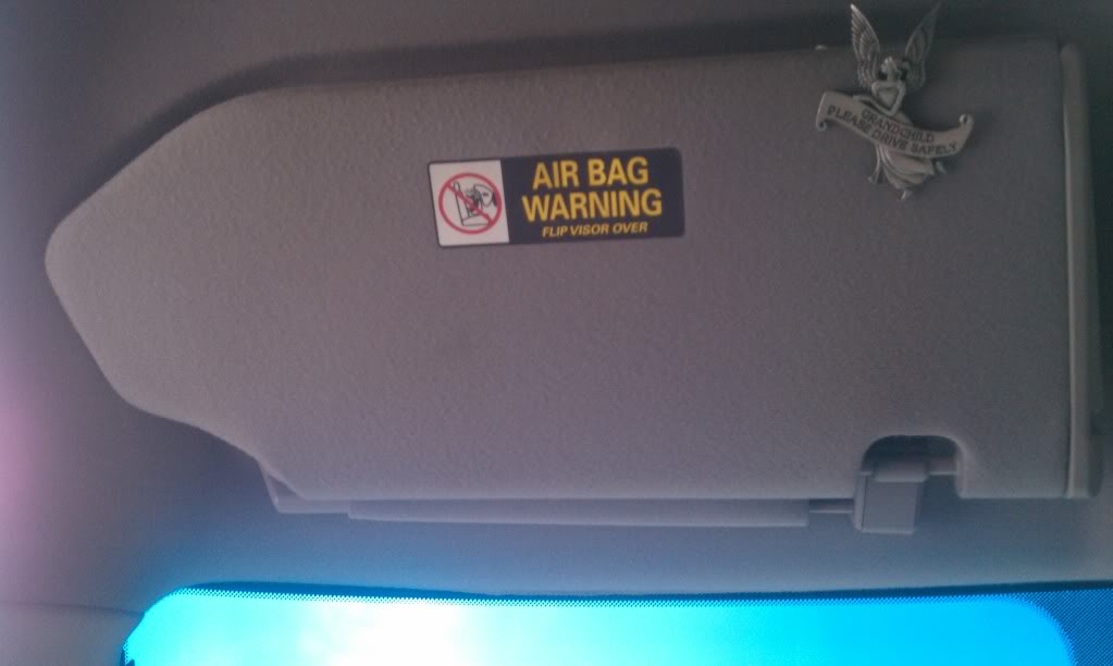
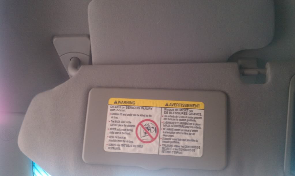
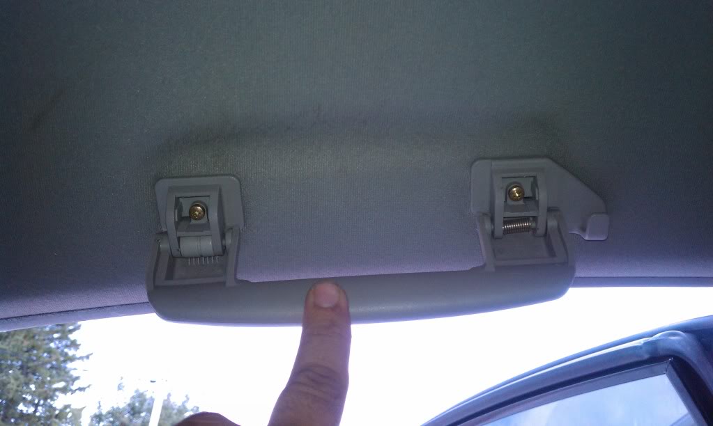
Third, The Visors:
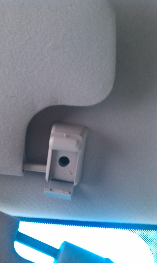
Pull down the visor, giving you access to the mounts on either side.
Using one of your pick tools, remove the plastic covers on each mount, revealing two Phillips head screws under the large mount and one Phillips head screw under the small mount.
Remove the three screws, and lower the visor, revealing the harness for the vanity lights.
Unplug the harness, and repeat for the other side.
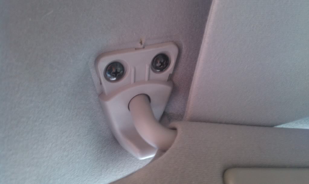
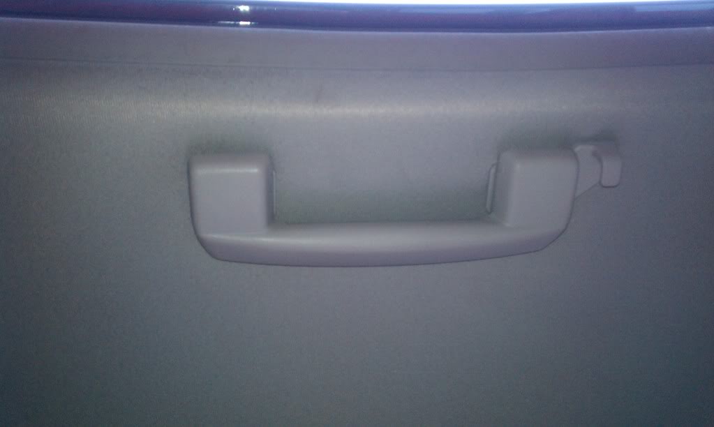
Fourth, I did the “Oh-Shit” Handles:
“Open” the handle by pulling down, and you will see a plastic cover on each end. Use one of your pick tools to remove those plastic covers, revealing two Phillips head screws underneath.
Remove the two screws, and the handle will come right off. Repeat for the other 2 handles.
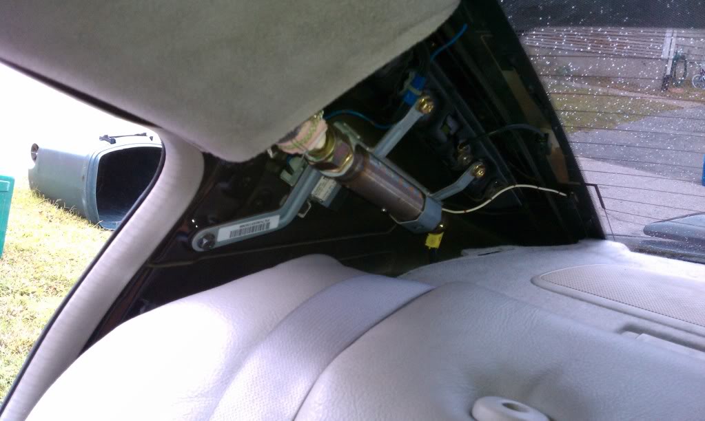
Fifth, I went to the B-Pillars:
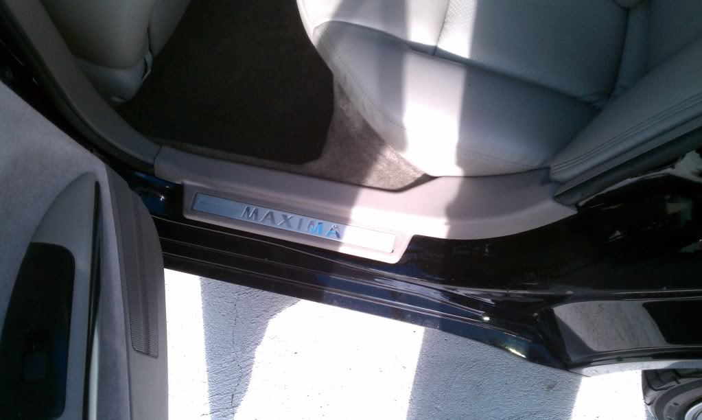
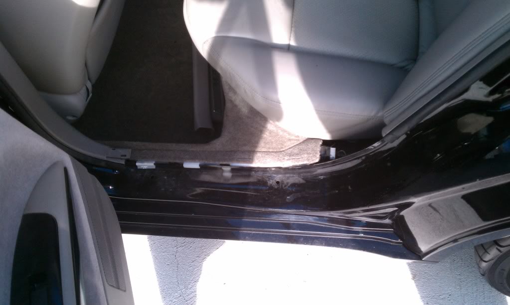
The B-Pillars take a little more work to get out. You could probably sneak them out easier, but I didn’t want to risk snapping a clip or breaking anything, so I took this route. Start by removing the moldings in the bottom of the front door. Just use your panel popping tool or flathead screwdriver to get under it from the outside edge, and pop it up carefully. Do the same for the molding inside the bottom of the rear door.
Next, remove the lower B-Pillar piece, by using the panel popping tool to pop the clips from the bottom up. Once you have all of the clips popped out, remove the piece and set it aside.
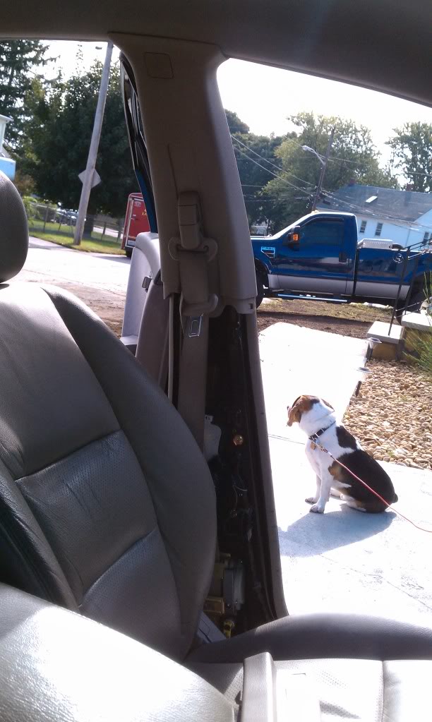
Next, you have to remove the seatbelt from the pillar. If you pull the adjustment tab on the seatbelt in the middle of the pillar, and twist it, it will reveal a 12mm bolt underneath holding the belt on. Remove that bolt, and let the belt hang.
Next, you need to pop the “SRS Airbag” pieces off the pillar with one of your pic tools, revealing a 10MM bolt underneath.
Unbolt that bolt, and you are ready to remove the pillar. Start at the bottom with your panel popping tool, and pop the clips out from bottom up, and the remove the pillar. Repeat for other side.
Now that the pillar is removed, re-attach the seatbelt if you plan on driving the vehicle while the headliner is removed. Also, reinstall the gold bolt that you removed from under the SRS Airbag piece, as that bolt helps hold the airbag in place.
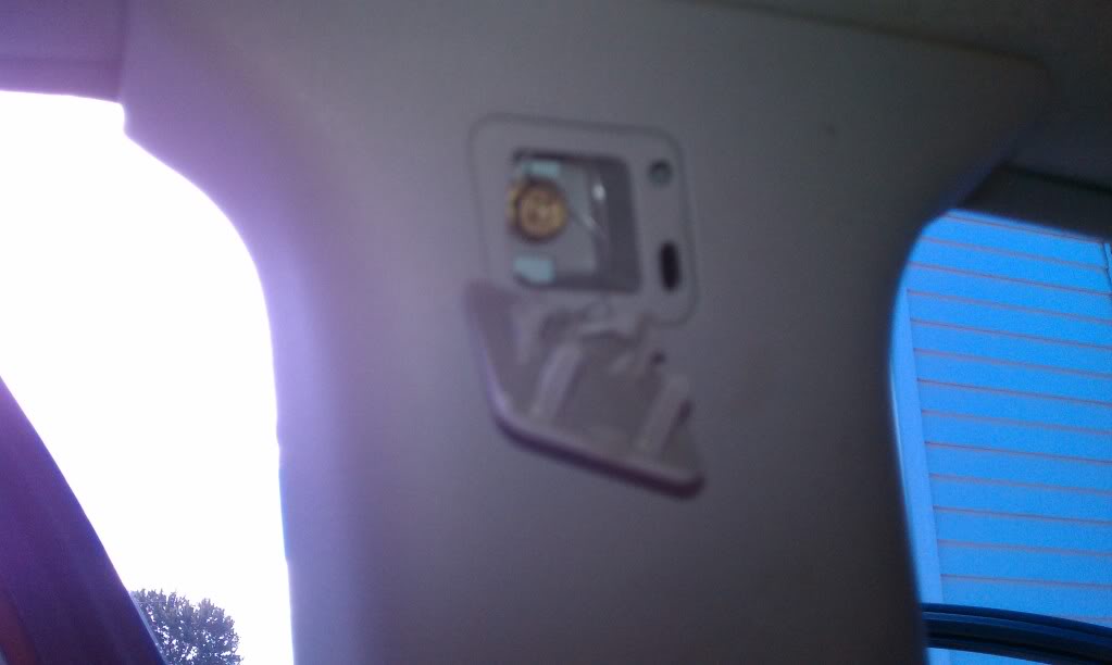
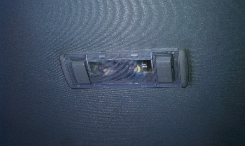
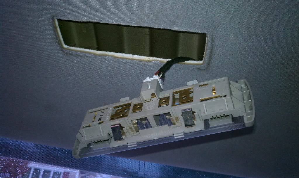
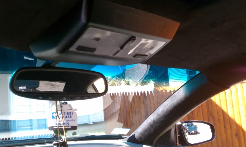
Sixth, The Rear Dome Lights:
Easily pull down on the dome light assembly until it comes down, revealing the harness for the lights.
Unplug the harness, and move on.
Seventh, The C-Pillars:
With your panel popping tool, start popping the clips out at the top of the pillar where it meets the headliner. From there, work your way down to the rear deck, and once you have popped all of the clips out, you will have to play with it and wiggle it out. Repeat for other side.
At this point, you have removed everything holding the headliner up other then the stuff on the headliner itself.
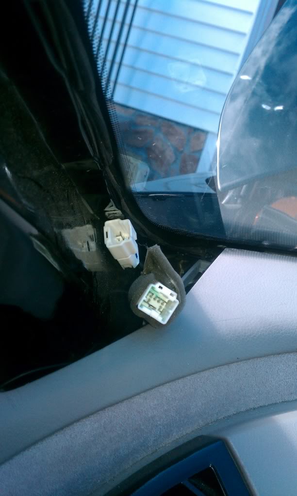
Next, unplug the two harnesses at the bottom of the driver’s side window. These harnesses are what run everything you just removed (vanity lights, dome lights, etc.), they have NOTHING to do with the airbags.
Now that the harnesses are unplugged, remove the three clips holding them to the pillar going up to the headliner.
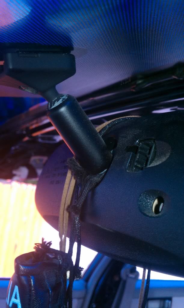
Next, unplug the harness on the rear-view mirror that runs to the harness, and let it hang.
Ok, so now the big drop down starts. Starting at the front doors, slip the headliner out from under the door moldings, so that it starts to hang. Continue on to the back doors as well, so that the headliner is free from front to back on both sides of the vehicle.
Now that that’s done, start to pull down the headliner from the middle of the front windshield. As you see/feel the Velcro release, work your way back, using the sunroof openings as spots to pull down on lightly. Once they are all undone, the headliner should hang, and you should notice a ground wire attached to a screw above where the driver’s side C-Pillar was.
Unbolt that, remove the ground wire, and put the bolt back in. You are now ready to wiggle the headliner assembly out of the vehicle.
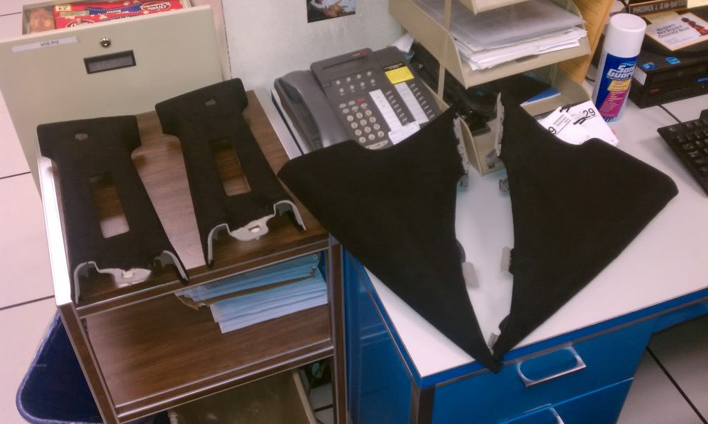
The Skyview Panels:
There is one silver 10mm nut, and one gold 10mm bolt holding on each panel. Remove those two items, and the only thing holding it on will be two white clips and a black metal clip, all of which just pop out. Drop it down, repeat for the other panel, and you are COMPLETELY done with the project. Well, other than putting it all back together.
The Sunroof Panel(Courtesy of DarkDog):
To remove you sunshade (slider panel), after you remove the headliner you will be able to see the rails your panel slides in. Towards the back of those panels, there are two white stops. There is a #1 Phillips screw in the top of each of these stops. Remove those screws, slide the stops out, and you will be able to pull your sunshade the whole way out through the back.
To reinstall, simply reverse the steps.. shade in, stops in place, screws in..
Alot of people dont think very high of doing this mod but if your not one of them and your interested enjoy!
What you need:
( all can be purchased at you local Lowe’s or Home Depot )
1. A razor blade or scissors
2. 3M red double sided heavy duty tape about $9.00
3. 1 9 foot roll of garage door bottom seal about $10.00
Steps:
1. Put the 3M tape on the door seal.
2. Clean the bottom of your bumper where the lip is going.
3. Start removing the tape plastic and attaching your new lip. lol
Below are the most commonly asked questions before starting this conversion. This very similar to getting the hybrid bumper which allows you to retain 2004-2006 Headlights/Hood with 2007/2008 Bumper.
“Where did you get your 2007 bumper?”
I got mine on eBay for about $50.00 on eBay, with about $50.00 in shipping. It was off a wrecked 2007.
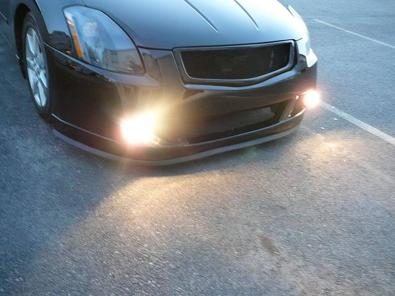
“What about the cornering lights in the stock bumper? I would lose those, so does the 2007 have corner lights?”
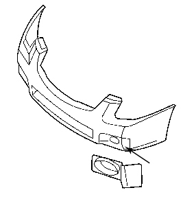
The stock 2007 does have cornering lights, but they’re in the headlight assembly. The 2007 has the FOGS down below (and we have them in the actual headlight assembly). You’d have to get some aftermarket fogs (the measurement is approximately 3.5″ x 3″, just in case you wanted to go that route. Or you can get 2007 OEM fogs, but those are always so expensive. Oh, and you’ll also have to get FINISH PANELS for the fogs. It’s the little matte plastic “covers” that go “around” the fog lights. It’s simply a cosmetic thing, and I purchased them from www.everythingnissan.com for $9.00 for both (you can also get the fogs there for a cheaper option). So that’s not an issue at all. Here’s what I’m talking about:
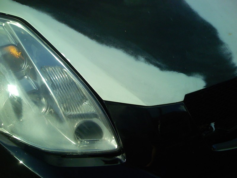
“Do the headlight line up?”
The headlights light up to an extent. There’s a SLIGHT gap under the light, but it’s nothing significant, and aligned properly there’s no gap at all. I’m still working on that. It’s nothing big though, and if you LIFT AND PUSH the bumper into place simultaneously, it should click in properly.
“What about the hood latch?”
This fits perfectly. No issues at all.
“How much did everything cost?”
– bumper – $100.00 (with shipping)
– contours around lights – $150.00
– paint bumper – $250.00 – paint hood – $250.00 – Finish panels – $9.00 – New 07 grille – $200.00 – 07 fog lights – varies. $70.00 – $300.00
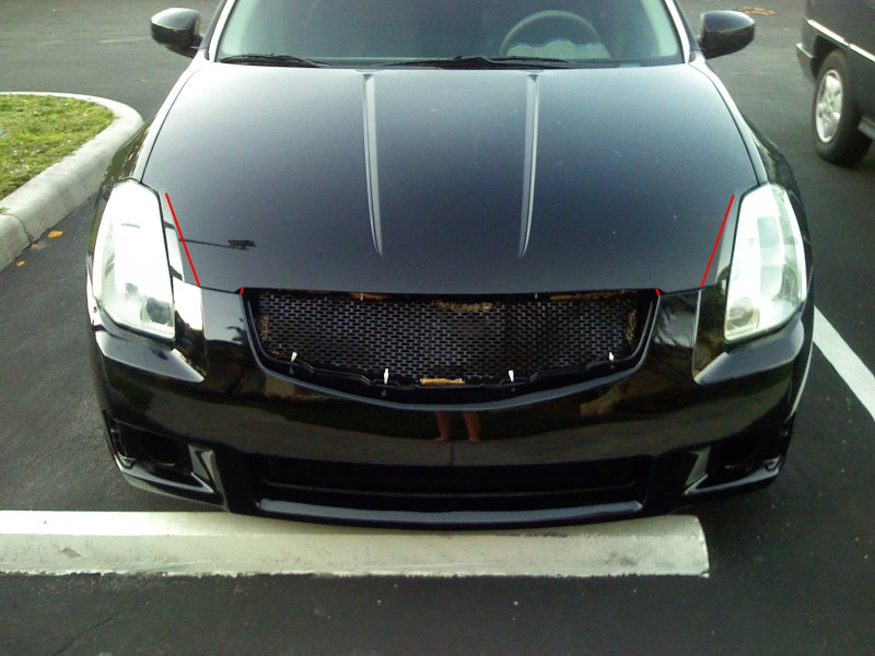
“What needs to be modified on the hood?”
The contour lines around the lights are different from the ’07 lines. Those need to be shaped to the right alignment. The hood needs to be extended a bit in the grille opening to line up properly. I actually just added a little bondo where the grille contours need to be lined-up, so that wasn’t a big deal. Oh, and there’s a slight overlap near the lights that needs to either be shaved or banged down. My bodyshop guy banged them down since the hood is aluminum. Keep in mind, after the hood work, you’re going to have to get the hood repainted. The red lines indicate where a body shop needs to bang and/or bondo to the right shape:
Contours:
Bondo in grille opening:
Reshape passenger headlamp:
Reshape driver headlamp:
Complete re-contouring:
Finished product:
“What did you ever do with the cornering light assembly and function?”
I have not done anything with the cornering assembly as of yet. I’m still in the market for some fog lights, and Luke said he’d help me wire them to be functional as fogs, not corners.
“Could you cop the 07 hood as well, instead of messing with the contours?”
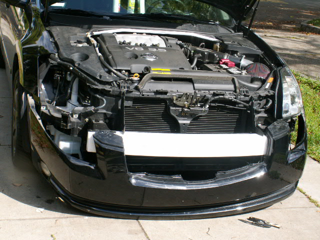
Well, it is possible, but then you’d have to cop the ’07 lights as well. OR modify THAT hood to fit the 04-06 lights. Either way a hood would have to be modified. At least as far as I can see. And if you did get the 07 lights, the quarter panels would have to be remolded too. I believe I went the cheapest and most effective route. Bumper Removal/Installation
The first step is to remove the grill. The plastic fasteners are easy to remove. If you have two small flat blade screwdrivers, like I didn’t have, you put each one on one side of the center part and pull it up. Then grab it and pull the whole fastener out. Put the grill aside somewhere where you won’t step on it. Now its time to remove the whole front bumper cover. You will need a Phillips screwdriver and your small flat blades. Start on either side of the cover. First you need to have access to some of the fasteners and screws. These are hidden behind the fender well plastic covers. Remove the fasteners that hold the fender well plastic. Remove enough of them that you can pry it open to get your arm in the TIGHT space to remove the screws. Once you get the fender well trim open, there are two screws that hold the cover on. They are hard to get at, but try. Unscrew the two screws. Then go underneath and see many fasteners that hold the underside plastic tray to the bumper cover. These were harder for me to remove. But I got them undone. Now do the other side. The front cover drops down exposing the lights. These are held on by 10 mm screws. Find them and remove them. Here is a pic of the car with cover removed and one headlight out:
Perform the reverse of removal for the 07 bumper cover and voila! Fog Light Rewire/Conversion
This section is for those planning to install OEM fog lights while controlling them using the factory fog light switch. After the 04-06 bumper is removed uninstall the headlights which are removable by 5-10mm bolts around the corners of the light. Once the light is removed perform the following rewire to allow the headlight fog lights to transform into an additional parking light circuit and for the bumper fog lights to now be the switch controlled fog light.


 Adjust the steering wheel all the way out and down. Inserting flat-head screwdriver in between two plastic pieces on the right side of the steering wheel where the windshield wiper knob is. Carefully pop apart plastic housing surrounding steering wheel and set aside.
 Remove plastic covering over gauges. Using flat-head screwdriver or thin plastic, slide under top middle plastic piece and slowly lift up to pop out. Then slide under each piece on left and right, pop out front part first, then lift and pull towards you.

 On top of gauge cluster is one single screw, remove this:
 Under gauge cluster are two hidden screws, unscrew both but don’t remove, it’s easier to pull out gauge cluster and screws will come out with it, then you can take them out.

.jpg)


")