The first step is to remove the grill. The plastic fasteners are easy to remove. If you have two small flat blade screwdrivers, like I didn’t have, you put each one on one side of the center part and pull it up. Then grab it and pull the whole fastener out. Put the grill aside somewhere where you won’t step on it.
Now its time to remove the whole front bumper cover. You will need a Phillips screwdriver and your small flat blades. Start on either side of the cover. First you need to have access to some of the fasteners and screws. These are hidden behind the fender well plastic covers. Remove the fasteners that hold the fender well plastic. Remove enough of them that you can pry it open to get your arm in the TIGHT space to remove the screws.
Once you get the fender well trim open, there are two screws that hold the cover on. They are hard to get at, but try. Unscrew the two screws. Then go underneath and see many fasteners that hold the underside plastic tray to the bumper cover. These were harder for me to remove. But I got them undone. Now do the other side.
The front cover drops down exposing the lights. These are held on by 10 mm screws. Find them and remove them. Here is a pic of the car with cover removed and one headlight out:
Scary, but its ok. The headlights are HEAVY so be careful. I pre-heated the oven to 225 degrees. Also, the area I was working in I wanted dry. So I cranked up the floor heater to 75 and really dried out the air.
Unscrew and remove the turn signal light. This is the easy part. Next, remove the metal box from the assembly. There is a bag of desiccant under the box inside. Remove it too. Unscrew the headlight cover and remove the wires from the cover. Unscrew the 4 screws that hold the headlight in place. Magnetize your screwdriver to help you. There are two other screws that hold a metal plate in. Loosen those and remove the headlight. Here is a pic of the headlight:
Put it in a plastic bag and seal it. Do NOT touch the bulb. Handle this as little as you can.
The fog light is difficult to remove. Unscrew one of the screws holding this spring wire in place. Carefully remove the spring and remove the bulb. Here are pics of the fog light:
Remove all brackets and anything with a screw. Do not touch the headlight adjustors. Now its time to bake it – 225 degrees for 15-20 minutes. Here is a pic of the light in the oven:
Remove light assembly with glove and use a putty knife to CAREFULLY pry apart the cover from the assembly. Do it cleanly and keep the sealant intact if u can.
Remove the chrome trim from the clear cover by unscrewing two screws. Here is a pic of the chrome trim:
Sand it with 1000 grit wet sand sand paper under running water until the chrome is scuffed. Tape the orange reflector. I tried to remove it and BROKE the chrome trim. Here is a pic of that disaster: Next, prime the trim. I used black Plasticote from Pep Boys. I primed the DRL lense because I was not going to use it. Its up to you if you want to or not. Here is a picture of it primed:
Then I painted it with gloss black paint using the Plasticote paint. I clear coated it also, I waited about 15 minutes for each coat to dry. Here is the trim after clear coat:
Now assemble the trim in the cover. Bake the assembly again for 15 minutes and put the cover back on. I used a damp towel to clamp the cover back on the light. I waited until the light assembly was totally cooled down before I put the headlights back in. Use the other light to help you to put back the lights and wiring.
Here is a picture of one light completed next to the other one:
Big difference, especially in person. The glare from the camera doesn’t show how nice the darkened light looks.
Do the other light and then install the lights in the car and reverse the order of removing the bumper cover and grill. Here are pictures taken after the lights were installed:
Before/After
A couple of tips:
Let the oven get completely preheated before putting the cardboard in. Make sure there is no tape on the piece of cardboard you use. Use the 2nd from bottom oven rack position.
I purchased some use Brembo brakes and had them PC red, I did not know any better and send them to get PC without removing the seals and piston. If I could do it again I would definitely remove everything before getting them PC. I could not find a DIY on G35driver so I decided to create this to help out other members.
For those that are curious the Brembo Front Calipers Rebuild Kit part # is: 41120-12U25
Rear Calipers Rebuild Kit part # is: 44120-12U25. The kit comes with Brembo seals and O-rings along with bleeder screw caps. I want to thank Rob from Z1 Motorsports for the kit and help.
First remove the clips, pin, spring and brake pads. I didn’t take pictures of this process since there are several DIYs showing how to accomplish these. You should end up with something like this. I would recommend cleaning the hardware
Remove the dust boot. There is a small hole, use a small crew driver to pop it out gently. It should come out really smooth.
Do the same for the rest of the dust boot.
After all the boots have being removed, the next step is to remove the pistons. I took several towels and roll them up and put it in the middle of the calipers to absorb the impact. Then I use my air compressor to put pressure and pop out the pistons. The air should go in the same hole where you connect the brake line.
There are different items that can be use, the most common is a piece of wood. I didn’t have a piece of wood so I use the towels and it worked just fine for me. Just be very careful during this process because the pistons will shot out fast and make a loud pop.
In one of my calipers only one of the pistons came out. I push the one that came out back in and then retry to get them both out at the same time with the air compressor, but again only one came out. I got frustrated after several attempts and improvised by prying it out with two flat head screw driver. If this happens to you I would put tape or something to protect the calipers and pistons. If you put down even force on both screw driver it will slowly come out with not problem.
After you get the pistons out, carefully use a small screw driver to pick out the O-ring, it should come out very easily. Not shown in this pic, but clean the inside really good and then lube it with brake fluid.
Let the new seal soak up in brake fluid prior to putting in.
This is how it should look after inserting new seal.
Clean piston then soak it in brakefluid along with the dust boot.
Install new dust boot
Pull down on boot until it catches in the piston groove, like this
Then pull up
Put piston in the hole so it sits straight, not crooked
Push the piston in gently until you feel some resistance .
Then hold the caliper as if you are hugging it and push the piston in with your fingers tip
Apply EQUAL pressure with both hands and it will slowly go in, be patient.
You don’t need to use a vice grip, clamps, or other tools. If there’s a lot of reistance, take out the piston, clean it, relube it, and try again
It should look like this went done. Follow the previous steps for all calipers.
The next steps are for installing brake pads. I purchased Project Mu B-Force pads, heard some good reviews. I put on brake quite to avoid brake noise. The rest of the pictures are really self explanatory.
If any one has any better way to perform any of these tasks please post it. This was my first time ever doing this I learned along the way. Peform at your own risk, I am not liable on anything that goes wrong using this guide.
The owner of this 6thgen (MLeo) had something that caught my eye on his car. When I asked him… he said its a Honda Accord lip. At first I didn’t believe him, but its 100% confirmed and 100% perfect fit.
For those looking for a new OEM style looking rear trunk spoiler…. here’s another option from the Honda Accord (08-09). I really like it and its super clean.
This write-up is for a 2003/2004. But the same steps are application to 6thgen Maxima. Also, for 7thgens you do not need brackets but the installation instructions still hold.
This DIY will take you through the basic steps to remove the existing brake components (calipers, rotors, lines) in order to install the Akebono brake kit that is standard on the G37S and the 370Z Track model (I think it’s called “Track”..can’t remember).
I wanted to note one more thing, you don’t to completly purge your brake fluid for this installation. I needed to change mine out, it had been a year and a few track events so it was time for replacement. You can simply disconnect the lines and cap them, just make sure to bleed the system when you get everything put back together.
Front Rotors (14″ Stoptech Slotted): 27lbs each ()
Rear Rotors (13.8″ OEM blanks, vented): 18lbs each ()
I will weigh the existing components next week and update this thread to show the delta in both unsprung and rotating mass.
Some tools needed for the install: Floor jack and jack stands. I used stands for the front of the car and my floor jack to raise the rear via the rear differential.
Basic set of sockets, wrenches. A 7/8″ socket was required to remove the bolts on the front caliper.
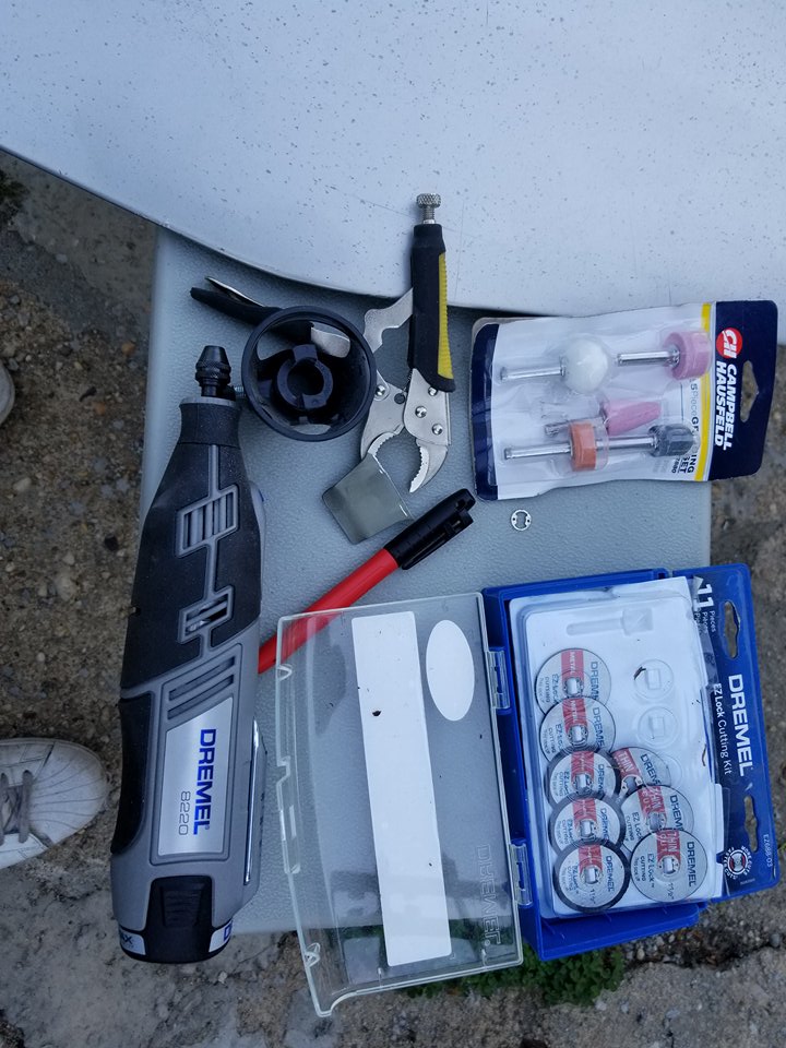
Tin snips, dremel, cutoff wheel or equivalent to remove/cut dust shields.
Vice grips
10mm open ended wrench (Akebono calliper bleeders)
Flathead screwdriver
Rubber mallet
Bowls and tubing to bleed brake system (I used 1/8” aquarium line)
Onto the install:
Break all lug nuts loose, raise car, remove wheels and set aside. You will have access to the existing rotor and caliper now.
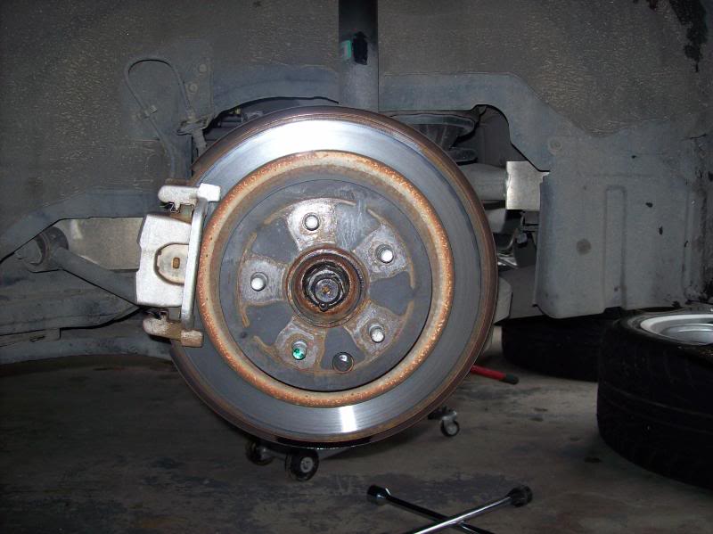
Front rotor/caliper
Rear rotor/caliper
Set up some bowls/cups (whatever works for you) under each caliper and drain brake fluid. Attach the tubing to the bleeder screw and slowly open the screw.
Rear drain setup
Front drain setup
I used the Motive 0107 bleeder to flush the brake system
Be very careful with brake fluid, it is highly corrosive and will eat through your clear coat and paint in a short amount of time.
Front caliper fluid drained
Rear caliper tubing
Rear caliper drained
Do this to all four corners. I started passenger rear, drivers rear, passenger front, then drivers front until all the fluid was evacuated from the system.
I bought stainless steel brake line with my kit, if you are using the OEM lines then ignore the next few steps.
Break loose the two bolts attaching the caliper. I used a 7/8” socket for these. If you have never removed these then it would help to spray some PB Blaster/WD40 on them and let them sit for a while.
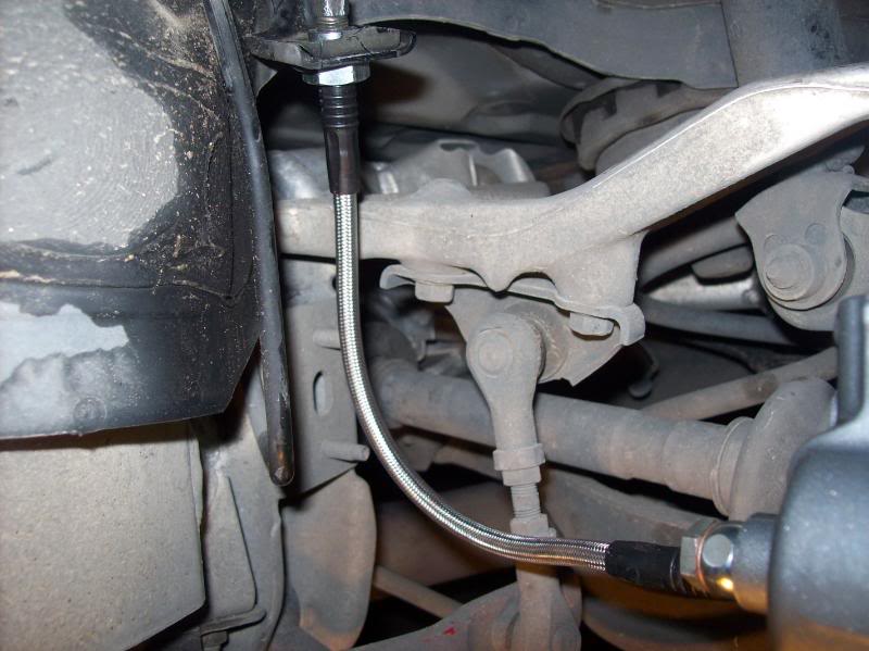
Remove the two 12mm bolts securing the OEM lines to the strut.
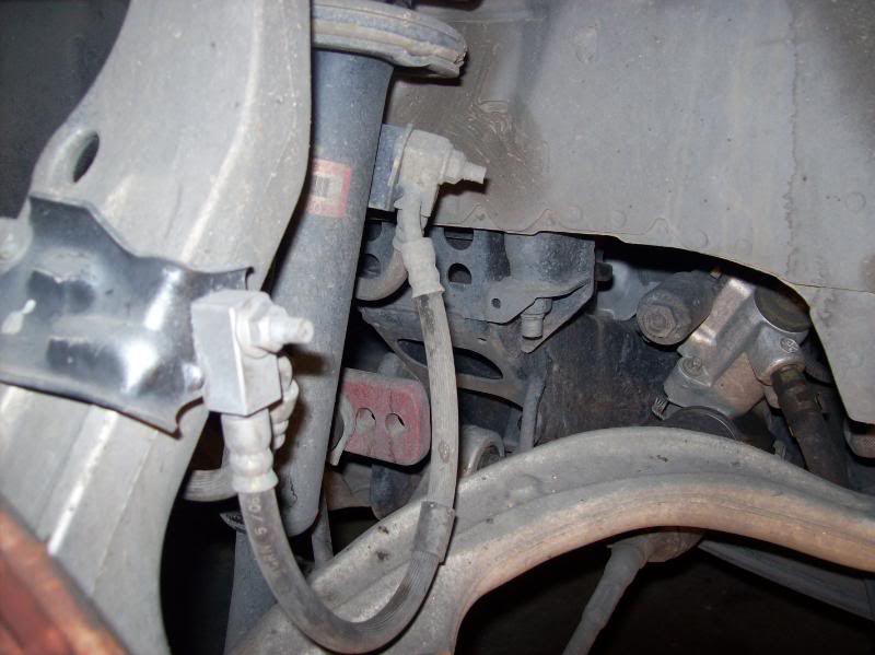
This is a tricky step, remove the clip that holds the OEM brake line to this bracket. There was quite a bit of dirt and debris in there, I used a small flathead and worked around the clip until it came out. I used a small pair of vice grips to loosen the nut.
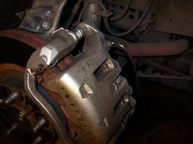
Now that the two caliper attach bolts are broken loose and the lines are unhooked, simply slide the caliper off the rotor. You may need to rock it back and forth a few times for it to come loose. Here’s one of the front calipers off the car.
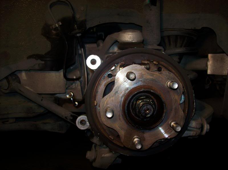
Now it’s time to remove the rotor. You may need to break out the rubber mallet for this one. Nothing like banging loudly on your car at midnight! Rotor removed and off the car.
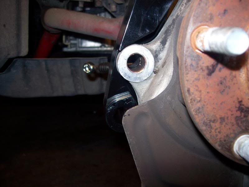
Now we have a clear shot of the dust shield. You MUST trim or remove the shields to get the new BBK to fit. I initially wanted to remove the shields but they are sandwiched in between the spindle and the main suspension components. I was able to remove 4 of the 5 17mm (I think) bolts, the last one I could not remove. This said, it was time to start hacking as much of the dust shield off as possible! You can get by with trimming a little, but I wanted that thing gone! If dirt or debris gets into the rotor it should be able to find its way out pretty easily.
This is one of the tabs that will get in the way (lower front)
Closeup of dust shield on
Dust shield trimmed to my liking.
Here’s the OEM front rotor next to the Stoptech rotor.
Do this for both front brakes. Now it’s time to go work on the rear brakes!
Again, if you are re-using your existing lines then skip this step. Loosen the nut attaching the flexible brake line to the hard line using a flared wrench or vice grips (same as front, except there are no attachments to the strut….much easier!)
Remove two 19mm bolts attaching the rear caliper to the car. Again, if you have never removed them then let them soak in PB Blaster or WD40. (Sorry, no good pics of this.)
Here’s where you get to bang on the car VERY violently. Make sure you release the parking brake first. The rear rotors seem to get stuck harder than the front rotors. I sprayed around the 5 bolts and hub with PB Blaster and let it sit a few minutes then started hitting it with the mallet. Hit the rotor along the back side, actually the dust shield. Also hit it along the outer perimeter of the rotor. Eventually (after a good 15 minutes for me) the rotor broke loose.
With the rotor removed we can start hacking away at the rear dust shield. The rear dust shield has an out ring that must be trimmed for the new larger rotors to fit. Again, I cut as much of the shield off as I could.
Rear dust shield hacked to pieces!
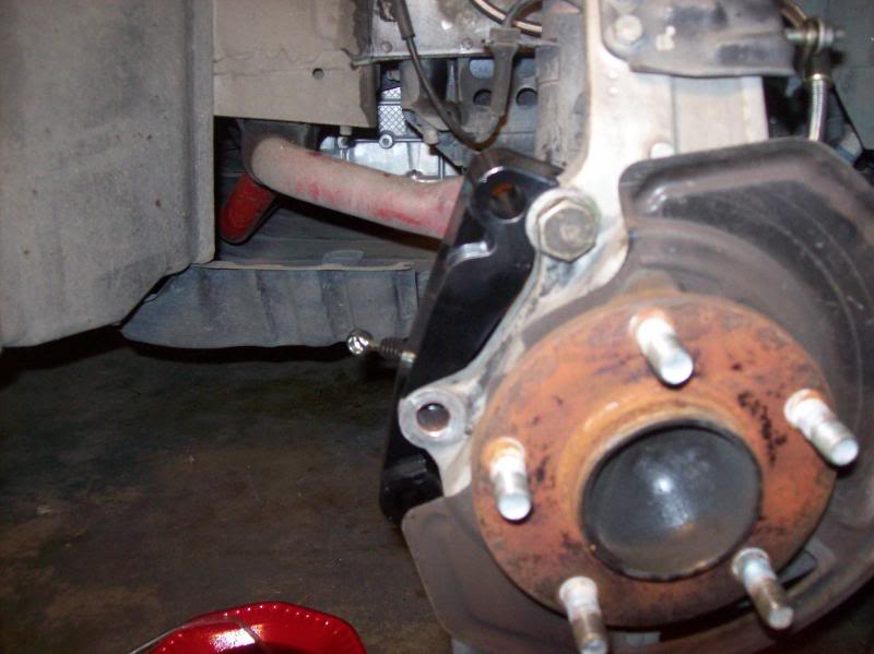
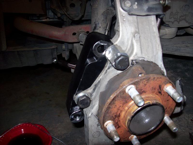
Now it’s time to look at the front brackets to attach the Akebono calipers. Unfortunately there were no instructions on how to install these. I looked at some pics online and it helped a little. The COZ bracket kit comes with four machined parts, two large brackets and two moon shaped pieces. After trying different combo to fit here is what works:
Now, the tricky part of this is to get the moon shaped piece aligned just right…there isn’t much room for error on this. If it is not aligned right then the upper caliper bolt holes will not line up. Here is what I eventually did after a few failures. With the rotor off the car, attach the large bracket as show. Then attach the moon piece, but do not tighten down. Attach the Akebono caliper to the bracket. Now, align the moon spacer so that the upper caliper bolt hole aligns with the caliper bracket and install bolt to secure calipers. Now that the caliper is secure and in place, go ahead and tighten down the moon shaped spacer. Remove the caliper and install the rotor.
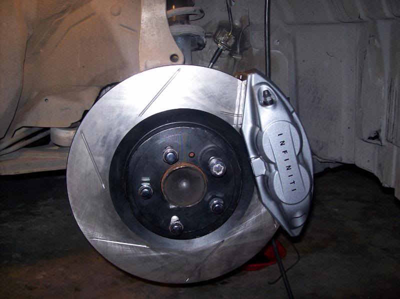
Now that the front rotors are on it’s time to build up the calipers. The kit comes with grease, pads, shims, pins, clips, cotter pins….everything you need. I didn’t take pics of
The build up because everyone was asleep and my hands had shim grease all over them. Here’s the front caliper on the car.
The front was a tight fit, hopefully it will loosen up a little after some driving. Now, install the caliper to the adapter bracket.
Attach the new brake lines to the caliper, 14mm bolt. No pics, but it’s pretty much error free.
The rear calipers are much easier to install. Build up the brake pad/shim/clip assembly and put in the caliper. Reuse the existing 17mm bolts to attach the caliper to the car.
Caliper/rotor on car,
Pad build up
Brake line installation
Now that everything is installed it’s now time to refill the system with brake fluid, reinstall the wheels, lower the car and brake in the pads. Make sure to lower the rear of the car first and put some tire chucks behind the tires before you lower the front so the car won’t roll back.
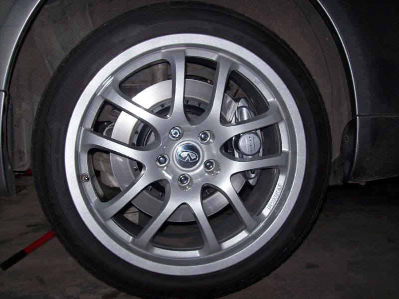
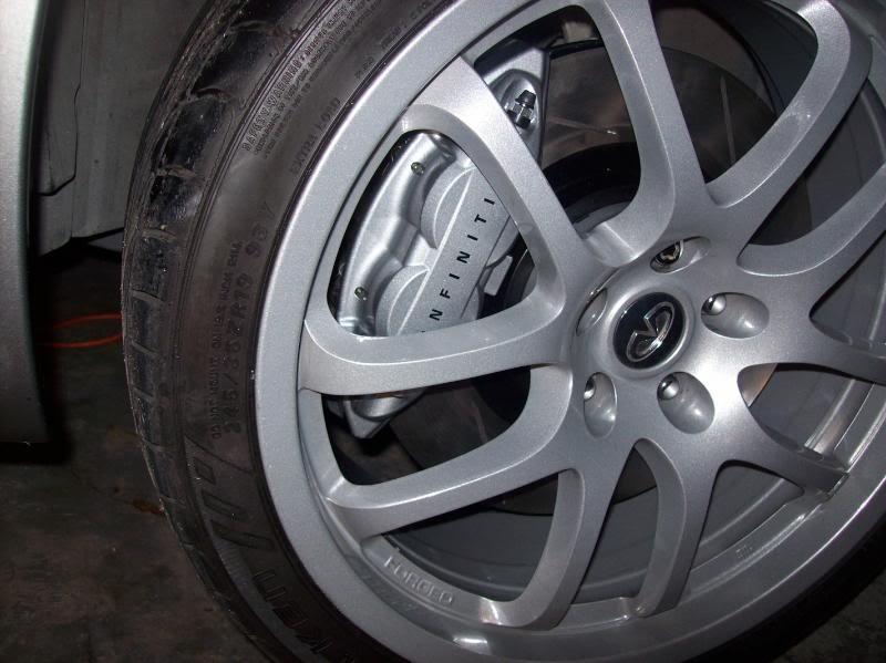
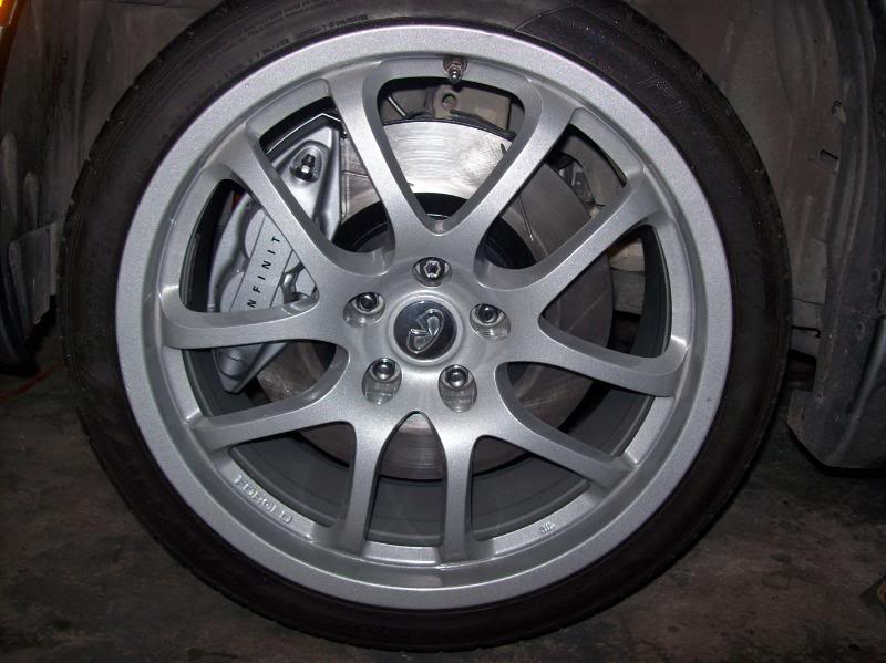
Here’s a few pics of mine installed.
Updates:
So I went for a quick drive around the neighborhood today. The pedal was very squishy and I had to pump the brakes to get adequate pressue to stop the car. Went home and checked all my lines, no leakes. Then I got to looking at the rear calipers. I had them installed with the bleeder screws facing down……BAD IDEA! (this is why you don’t work on cars at 2:00am!). I switched the rear calipers so the bleeder screw was on top, bled the system and drove again. Wow, what a change. The pedal is much more firm than stock. I am going to bed the brakes this afternoon sometime.
If you try to bleed the brakes with the screw at the bottom you will entrap some air in the top of the caliper. Always have the screw at the top so the fluid occupies the bottom of the caliper and fills its way to the top, releasing the air out of the system.
Changing the spark plugs on a 2002-2003 Maxima is not something you should have to do until around 100,000 miles. The stock plugs are platinum tipped and should last a very long time. Replacement of the plugs is something that Nissan recommends you “see your dealer” to do. The reason is that in order to replace the 3 plugs in the rear cylinder bank, the intake manifold upper and lower collectors have to be completely removed from the vehicle. To do this requires skill beyond the average Sunday mechanic, since there are many vacuum, electrical and coolant lines that have to come off in order to perform the job.
My car had slightly over 18,000 miles on it when I did the job, and it did not really need new plugs. The reason I ended up doing this job was because I strongly suspected one or more of my ignition coils were faulty, and try as I might I could not get Nissan to admit the problem or come up with a solution. I called Courtesy Nissan, ordered a set of ignition coils and plugs, and set about doing the job myself. I replaced all 6 ignition coils, and doing the spark plugs as well was simply for the sake of completeness.
I documented the entire process with pictures and text so that if there is anyone out there who wants to do the same, perhaps they will not be quite as intimidated as if they were going in cold. The job is not simple, and took me about 3.5 hours, but I did take a lunch break, and was also documenting the process with a digital camera.
Cost of the job was also not cheap – a set of 6 ignition coils from Courtesy Nissan cost me $333.48. The required gasket is another $18.40. The plugs themselves will run you $11.00 each. If all you really need to do is change your plugs, obviously you don’t need to buy coils, so then all you would need would be 6 plugs and the gasket. Do the job yourself and you will save quite a fortune in labor, as this job performed by the dealer would be many hundreds of dollars.
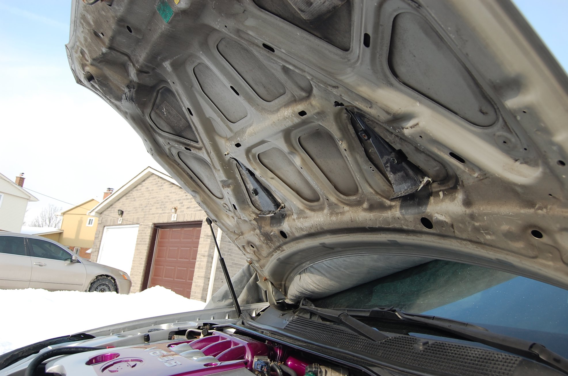
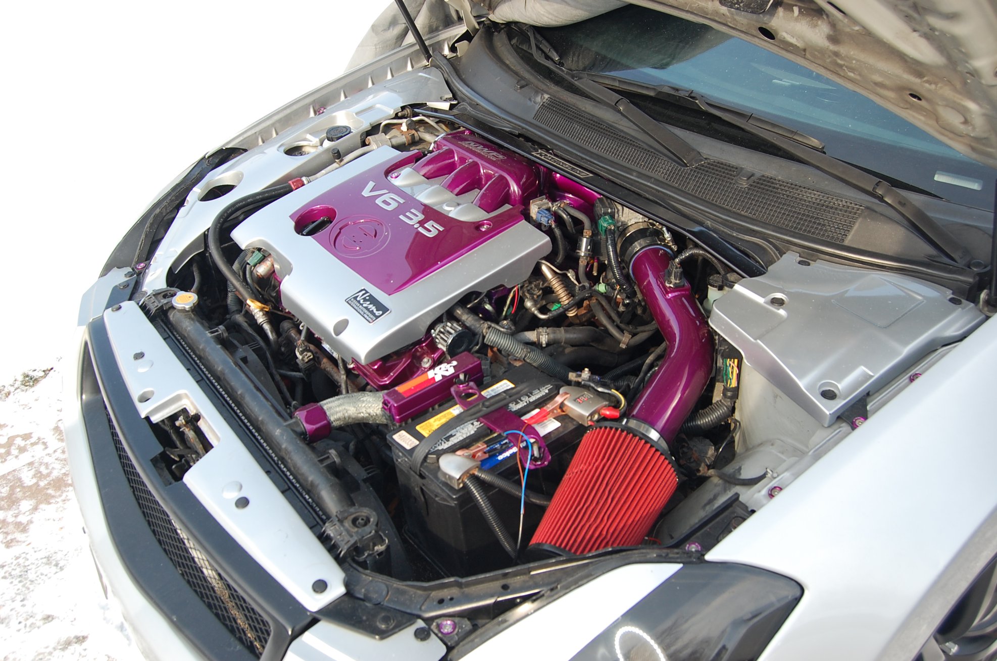
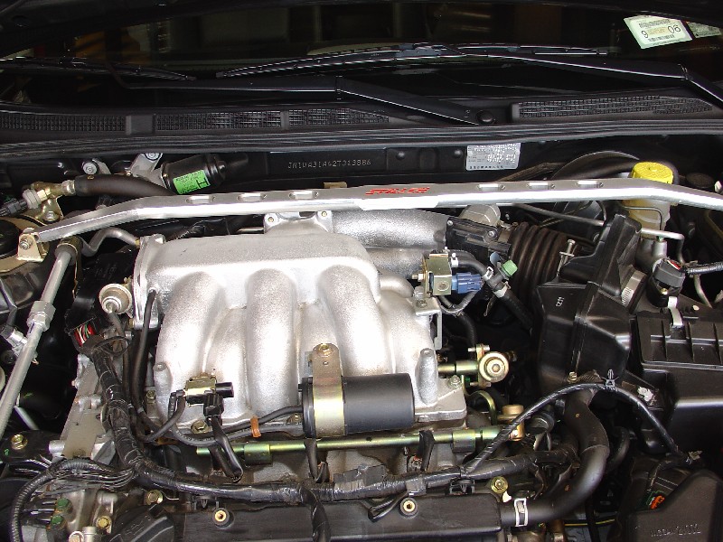
Here is the nice clean engine bay before going in with the chainsaw. If you have a front strut brace, as I did, it is probably not necessary to remove it, but I did simply to make it a little easier to lift the collector out. It only takes a minute or two anyway.
This pic still shows the strut brace in place (I removed it later). First step is to remove the 4 allen bolts securing the engine cover, and take it off.
A view near the firewall. The test is if you can reach and loosen these two bolts then you can do the rest of the job. It requires a 12mm socket with a long handle.
My method of doing this job will show you how it can be done without disconnecting so many vacuum lines, as I have seen others do. All you need to do is take a few parts off first so you can reach the bolts that attach the collector to the engine. Leave the electrical connector off, but put the valve back on.
Same idea with the vacuum tank. Take it off only so you can reach the attachment bolts. Then put it, and the VIAS control solenoid valve back on.
Once you get these 3 bolts, and 2 nuts off, you can go ahead and put the VIAS and vacuum tanks back on the collector.
Don’t take these off! No need to. You’ll see why later.
Two vacuum lines which need to come off. Slide the compression clamp down, and twist the hose off. Easy.
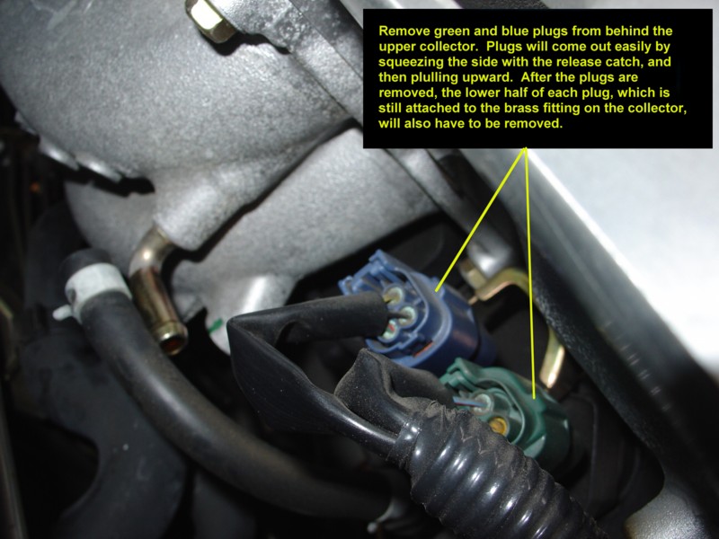
These electrical connectors need to be popped off. Be careful you don’t break them.
You also have to release and then slide the lower half off their brass fitting, or you won’t be able to lift the collector assembly off.
Again, another picture before going in with the chainsaw.
Loosen the screw holding the rubber connector to the intake. Leave the other side alone. It will stay.
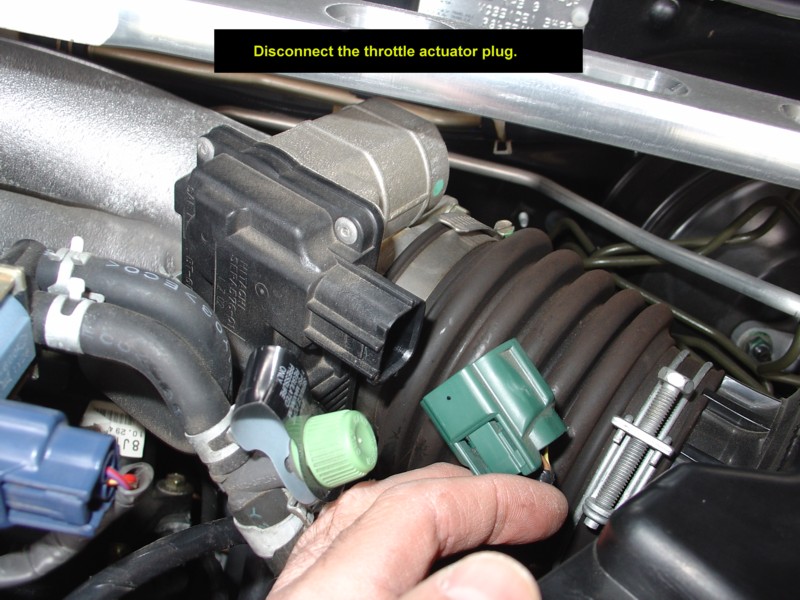
Unplug your “drive by wire” electrical connector, for the electronic throttle.
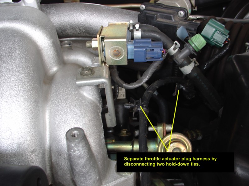
Pop out the two plastic harness holders.
Get the wire out of the way.
Remove this plug, take the 10mm bolt out, then put the plug back in.
Make room…..
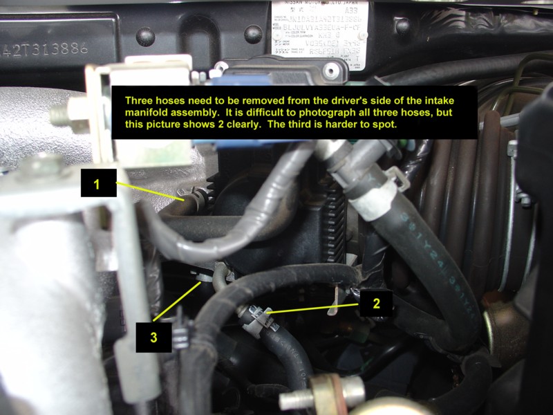
This was a tough picture to take. A little trick here – disconnect hoses 1 and 2 right at the area pointed to by the yellow line. Be prepared for a little bit of coolant to spill out when you disconnect hose #2.
Important – disconnect hose #3, not where you see the yellow line here, but at the other end of the hose. You will never in a million years reach this hose where the arrow is pointing, but you can reach it at the other end.
Slide the compression clamps down before you try to take these hoses off.
Just another view at lines #1 and #2.
Removing hose #1.
After all of the hoses and electrical connectors come off, you can lift the entire intake collector assembly up and out.
This is what the engine bay looks like with the collector assembly off.
Another view of the engine bay.
The collector assembly is rather large, but it is actually very light. I took the opportunity to clean mine up with some Gumout intake cleaner. Note that hose #3 is still attached to the collector!
Note how all of the assemblies remain attached when the collector comes off.
Here is a side view.
The procedure to remove the coils is the same for the front bank as it is for the rear. Just take the 10mm bolt out, unplug the connector and pull it right out.
This is what one coil looks like.
Use a spark plug wrench to remove each plug.
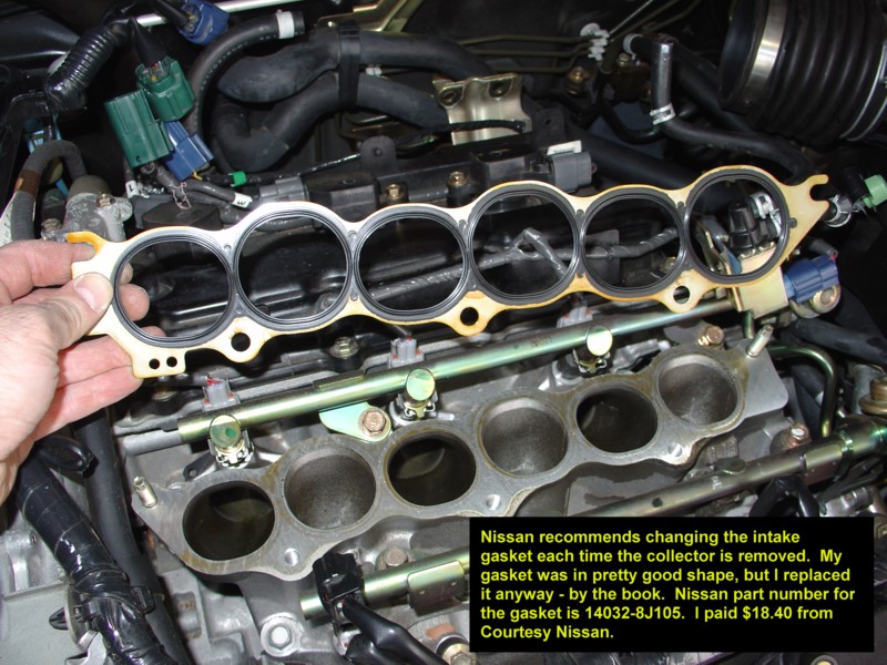
Nissan recommends you change this gasket any time the collector comes off. It is an expensive gasket, but why risk it? Buy a new one.
I do not show re-assembly here, but just follow these steps in reverse order. I hope I have de-mystified this process a little bit, and that you might be inspired to do this job yourself when the time comes. Good Luck, and you can do it.
For your 6thgen’s you need either the 30MM Aluminum or 30MM Iron Z32 Calipers for proper fitment. They are 4-Piston calipers. You will also need the brackets for them. You can usually find the calipers on eBay for good pricing. I would say approx. $200-$250 for a good set of rebuilt calipers.
Weight Difference:
Stock: Approx. 15 LBS
300ZX: Approx. 6 LBS The brackets used to be made by a member Matt Blehm. They are no longer available. However, you can find them used on the forums or Facebook groups from time to time.
The following is a comparison of some different Z32 300ZX brake calipers.
The “26mm Aluminum” calipers were used ONLY on 1990 non-turbos. They used a 280mm x 26mm rotor.
The “30mm Aluminum” calipers were used on 1990 Twin-turbos and ALL 1991-1992.5 300ZX’s (both turbo and non-turbo alike). They used a 280mm x 30mm rotor.
The “30mm Iron” calipers were used on ALL 1992.5-1996 300ZX’s (both turbo and non-turbo alike). They also used the 280mm x 30mm rotor.
Of course, the easiest way to tell aluminum from iron is to use a magnet, but I hope this helps some people trying to figure out what they’ve got/are getting if buying with just a picture for info.
My Setup:
4-Piston 300ZX TT Calipers
12.9″ Custom Rotors
Matt Blemco Brackets (Direct Bolt on) Kit Costs Approx. $200.00
Step 1: Remove shifter knob – Shifter knob is made of two parts, the leather handle, and the lower aluminum-looking cone-shaped piece. Grasp the cone-shaped lower piece, rotate counter-clockwise and pull down at the same time to release from shifter handle. Once this is done, there is a small gold clip holding the handle in place, remove this and handle will slide off, remove this as cone-shaped piece.
WARNING:
If you twist the shift knob thing as instructed you will end up breaking it. You just need to pull down on that plastic piece. There is a TSB addressing this issue.
Step 2: Remove wood-colored faceplate and shifter piece – Open cup holder door. Using your fingers, press along edge of wood piece where cup holder door goes and pull up. Gentle but heavy force may be needed to pull up plate. Make sure you are slightly pushing the side of the plate inwards while you do this. Once you get the end of it released, you’ll need to put the key in the ignition, turn it till the air comes on, put foot on the brake and move shifter knob into the neutral position. Lift up the whole plate to completely release. Underneath there are two connectors, one brown and one white, that you will need to disconnect before removing plate. Set aside.
Step 3: remove two lower screws that hold the dash kit in place, place them in a safe place. Use fingers on inside of lower storage area (below cassette opening) to pull out the dash kit and release from its clips. Remove lower half first, then pull out upper half. there is another connector on the back of that piece that needs to be unplugged. Set dash kit aside.
Step 4: Remove 2 screws holding in climate/audio control panel and LED screen. Holding this panel from underneath the radio controls, Pull piece outwards. The two middle air vents are also attached, and will come out as well. Lift out lower end first, then tilt upwards to release clips holding in the top edge. One connector on the back needs to be removed.
Step 5: Remove LED screen: remove 4 small gold screws on both sides of LED screen housing to separate screen from the rest of the panel.
Now you have successfully removed the LED screen. Pretty easy! To put back in, screw 4 gold screws back in, put whole panel piece back in first by inserting clips on top edge back through their holes, then slowly lower front edge down while making sure top edge stays flush with rest of dash. Carefully reconnect the plug, then lower all the way back flush. Screw back in the 2 screws. take Dash kit, reconnect wires, pop in the top part first back into slots, then lower part, then screw in 2 screws at bottom. Put the car back in neutral, plug in 2 connectors to shifter panel (brown and white), then slip shifter tube through the hole on the shifter panel, and carefully fit the panel back into place, starting with the edge closest to the dash and ending with the edge closest to the armrest/cup holder. Place cone part of shifter back over steel tube, place shifter knob on and carefully slide the gold clip back through the white part of the shifter knob, it should line up with the 2 grooves on either side of the knob and the 2 grooves on steel tube. Slide cone-shaped part back up and carefully rotate over gold clip until its tight. It may take a couple tries to get this last part right.
This is for those who would like to install the 7thgen Mirrors on their 6thgens. Considering they are from a different car the fit really well, not perfect but pretty damn close!
The holes for the new mirrors do not match up so all 3 need to be re-drilled. I basically held the mirrors up where it needed to sit and marked the holes and drilled them through. Also there’s a small plastic clip that needs to be removed, it helps hold the tweeter cover in place but also keeps the new mirrors from sitting flush.
I hoped the plug would be the same (of course it wasn’t) or at least the wires would be the same colors (and they weren’t) So I am waiting to get the wiring breakdown for both mirrors so I can hook up the heat, adjust and folding features.
I did want to hook up the blinkers and I knew that since the 6th gen doesn’t have them I would have to hook these up from scratch. So I looked in the stickies and found which colors the wires we’re because I wanted to tap into them at the BCM instead of running to the front of the car.
The wires at the BCM are as follows:
Turn Signal(L) green/black + BCM, pin 45
Turn Signal(R) green/yellow + BCM, pin 46
Notes: The BCM (Body Control Module) is between the steering column and the fuse box.
So I simply ran wire taps to these wires:
I ran a ground wire from one of the screws inside the door. I then ran the power wire through the side outlet where all the OEM wiring goes to the door (I fed the wire through with a coat hanger, rookie style!) For the passenger side I had to run the wire all the way across under the dash, I snaked it through and used zip ties to keep it in place (I also dropped the glove box to make it easier) I then ran it through to the door with the other OEM wires as on the driver side.
(passenger side, behind the glove box)
Now the trick was to find out which wires ran the blinkers so through a long process of elimination (lucky for you!!) I figured it out. On the 7th gen mirror plug, the orange wire is the positive and the pink wire is the ground, so I again tapped into these (I didn’t want to just cut any wires at this point due to the fact that I’m not sure exactly how I am going to hook up the rest of the stuff later.


 Scary, but its ok. The headlights are HEAVY so be careful. I pre-heated the oven to 225 degrees. Also, the area I was working in I wanted dry. So I cranked up the floor heater to 75 and really dried out the air.
 Put it in a plastic bag and seal it. Do NOT touch the bulb. Handle this as little as you can.
 Remove all brackets and anything with a screw. Do not touch the headlight adjustors. Now its time to bake it – 225 degrees for 15-20 minutes. Here is a pic of the light in the oven:


 Next, prime the trim. I used black Plasticote from Pep Boys. I primed the DRL lense because I was not going to use it. Its up to you if you want to or not. Here is a picture of it primed:


")


)")


.jpg)


 WARNING:


 Step 3: remove two lower screws that hold the dash kit in place, place them in a safe place. Use fingers on inside of lower storage area (below cassette opening) to pull out the dash kit and release from its clips. Remove lower half first, then pull out upper half. there is another connector on the back of that piece that needs to be unplugged. Set dash kit aside.
 Step 4: Remove 2 screws holding in climate/audio control panel and LED screen. Holding this panel from underneath the radio controls, Pull piece outwards. The two middle air vents are also attached, and will come out as well. Lift out lower end first, then tilt upwards to release clips holding in the top edge. One connector on the back needs to be removed.

 Step 5: Remove LED screen: remove 4 small gold screws on both sides of LED screen housing to separate screen from the rest of the panel.
 I hoped the plug would be the same (of course it wasn’t) or at least the wires would be the same colors (and they weren’t) So I am waiting to get the wiring breakdown for both mirrors so I can hook up the heat, adjust and folding features.
 I ran a ground wire from one of the screws inside the door. I then ran the power wire through the side outlet where all the OEM wiring goes to the door (I fed the wire through with a coat hanger, rookie style!) For the passenger side I had to run the wire all the way across under the dash, I snaked it through and used zip ties to keep it in place (I also dropped the glove box to make it easier) I then ran it through to the door with the other OEM wires as on the driver side.
 Now the trick was to find out which wires ran the blinkers so through a long process of elimination (lucky for you!!) I figured it out. On the 7th gen mirror plug, the orange wire is the positive and the pink wire is the ground, so I again tapped into these (I didn’t want to just cut any wires at this point due to the fact that I’m not sure exactly how I am going to hook up the rest of the stuff later.

