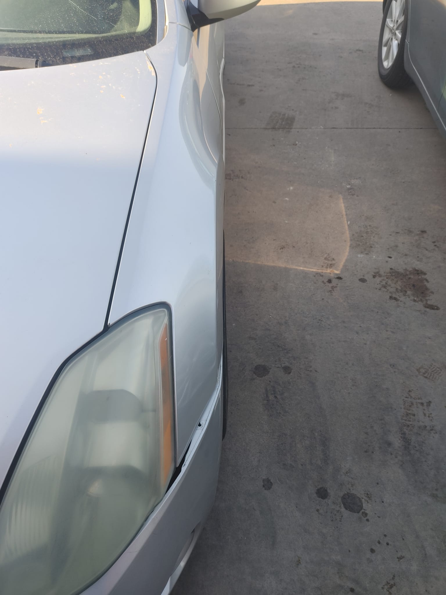
Owner: Kenlly Espinal
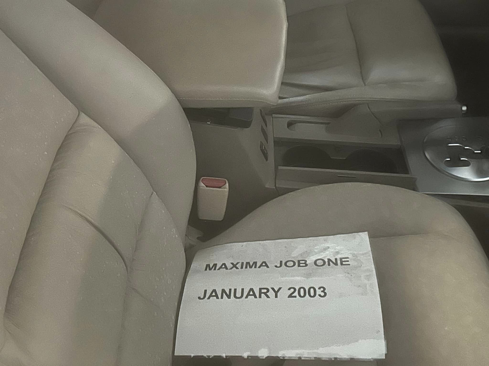
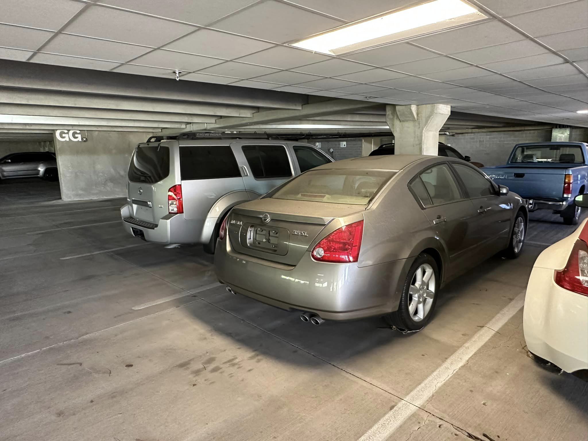
Year: 2004
Model: Maxima
Color: Silver
Engine: VQ35DE
Transmission: 5-Speed Automatic
Trim: SE


![]()


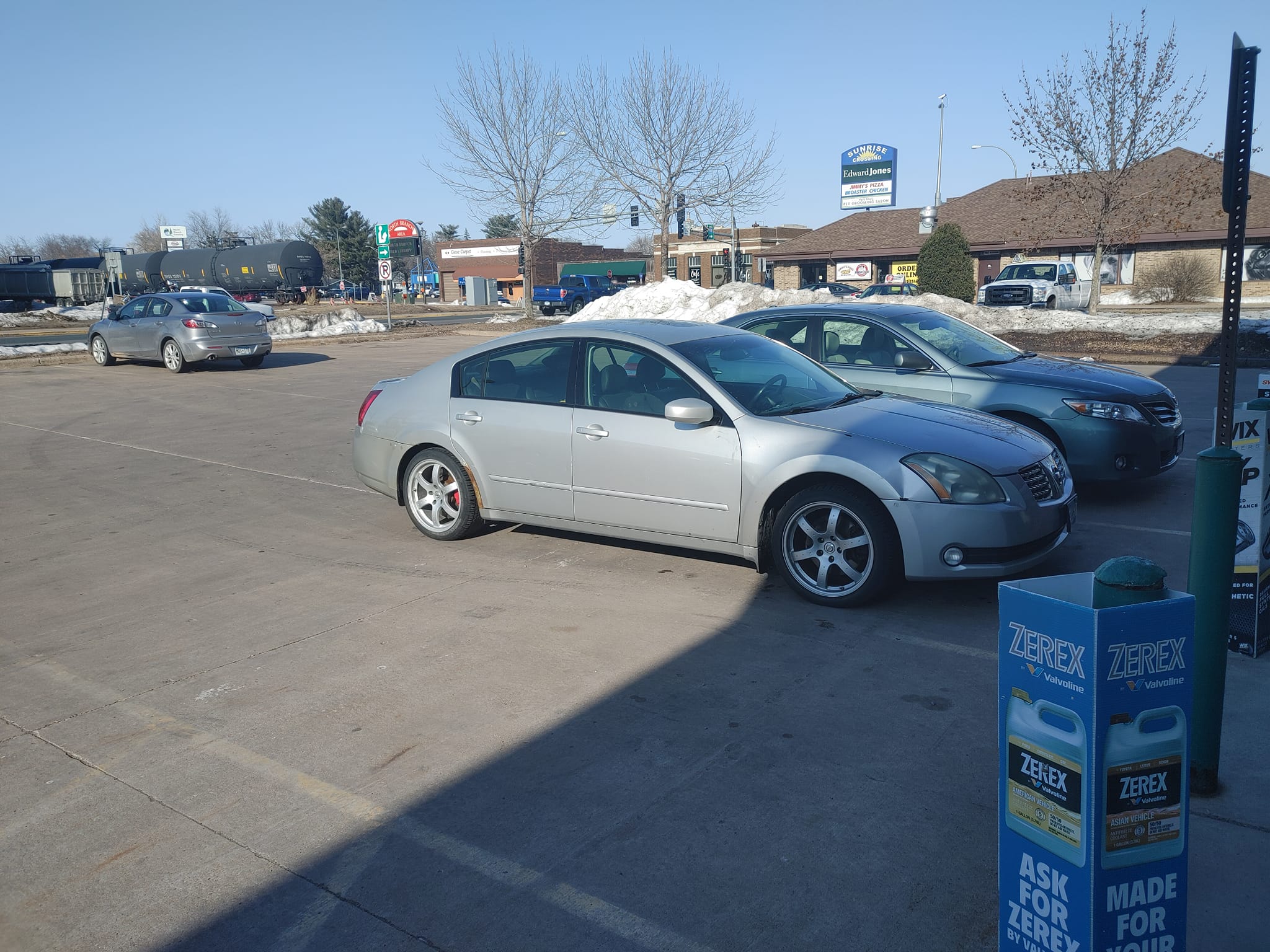
Owner: Kenlly Espinal
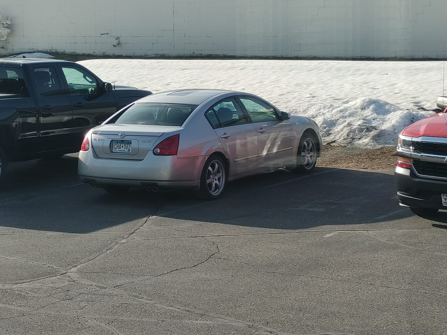
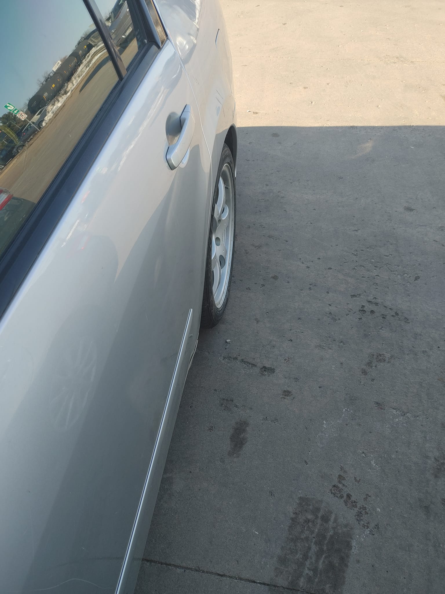
Year: 2004
Model: Maxima
Color: Silver
Engine: VQ35DE
Transmission: 5-Speed Automatic
Trim: SE
![]()


")
Credit: Travis Barker
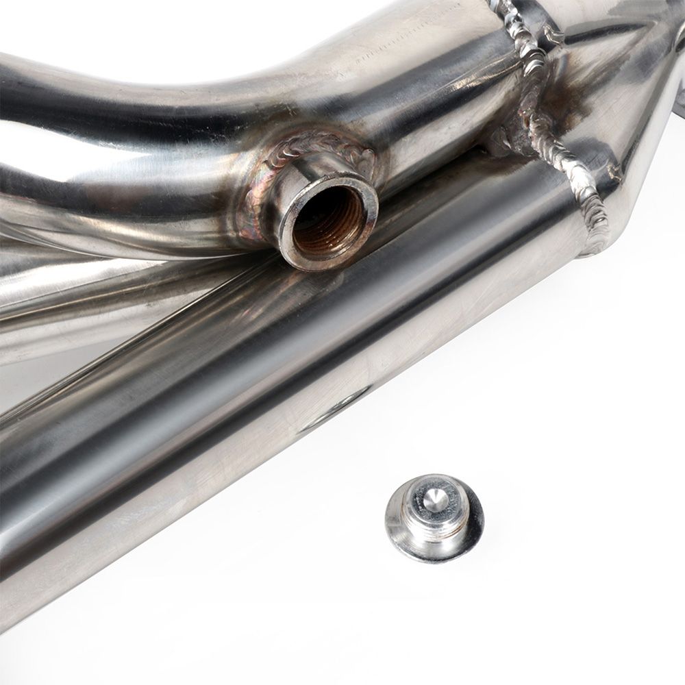
Photo of Power Steering Switch Plug:
![]()
")
Original Source Credit: http://www.nisformance.com/Articles.asp?ID=252
This article shows how to swap a 2007+ Altima 3.5L VQ35 engine, or 2009+ Maxima 3.5L engine into older Nissan Maxima’s. Including the 2002-2006 Altima (3.5L) and 2002-2008 Maxima’s. This motor swap is referred to as the 2nd Generation (Gen2/Gen3) VQ35DE swap.
There are three generations of the front wheel drive VQ35DE engine.
2nd Generation VQ35DE Swap Kit ($230.00)
Order Link: http://www.nisformance.com/2nd-3rd-Gen-VQ35DE-swap-kit-p/hrkitv2.htm

EPS Tuning Oil Gallery Gasket/Hardware Kit 2nd Generation VQ35DE engine ($60.00)
Order Link: http://www.nisformance.com/EPS-Tuning-Oil-Gallery-Gasket-Hardware-Kit-p/oilgallerykitfwdhr.htm

There are a few things to keep in mind before beginning your swap:

Depending on where your motor came from, there may be a lot of ‘extra’ pieces still attached to it. Some of these will just get in your way while you prep your motor, some can’t be used for this swap.

 ** The injector rail may also be removed, but that isn’t necessary.
Some parts of the motor will need to be cut somehow (tools, methods and results will vary) to allow for proper fitment and function once it’s reinstalled.
** Because of some concerns about the integrity of the stock oil gallery gasket, we at NISformance strongly recommend replacing it in this step. **


*Please note that we now offer a completely bolt on trigger wheel that eliminates the need to modify your stock trigger wheels*

If you choose to modify your stock trigger wheels, please note that this is a VERY important step and it must be done very carefully for your car to run properly. You have to be extremely accurate.
Apart from the wiring, adjusting the signal wheel is the most detailed work you need to do on the swap. It is important to be very accurate when cutting or grinding, and it’s also extremely important to assemble everything correctly at the end of this step. Pay close attention to the pictures and make sure that your work looks EXACTLY the same!
*You will need to modify your 5/16 Allen key by cutting the arm down so that it is approximately 3/8″ long. This is your ‘special tool’ that you will need to use in this part of the swap.


V2 inverters are single channel. One inverter is required for each camshaft position sensor.
Wiring for cam sensor signal inverter
Picture below demonstrates the older style DE cam sensor plug that is cut off when wiring in inverter with required wiring

The wiring harness in your car needs to be connected to the newer motor, and it’s not just a ‘plug-and-play’ situation. These diagrams show you the changes that need to be made to make your DE harness control your HR motor:

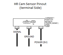
** THESE WIRE CONNECTIONS ARE CRITICAL. MAKE SURE THAT THEY ARE CONNECTED CORRECTLY (ACCORDING TO THE INSTRUCTIONS), AND SECURELY. TWISTING THEM TOGETHER IS NOT GOOD ENOUGH. **
The stock cam signal wire will be intercepted (cut) by the cam signal inverter supplied with the swap kit. There are six wires on the cam signal inverter…here’s how you connect them:
For Cam #1…cut the existing wire:
For Cam #2…cut the existing wire:
![]()
")
Credit: Josh Go Hard Neal
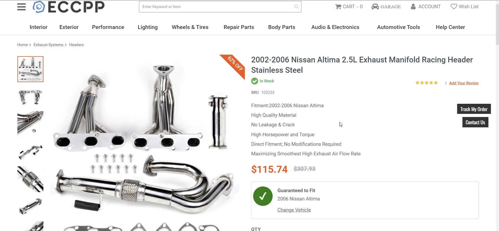
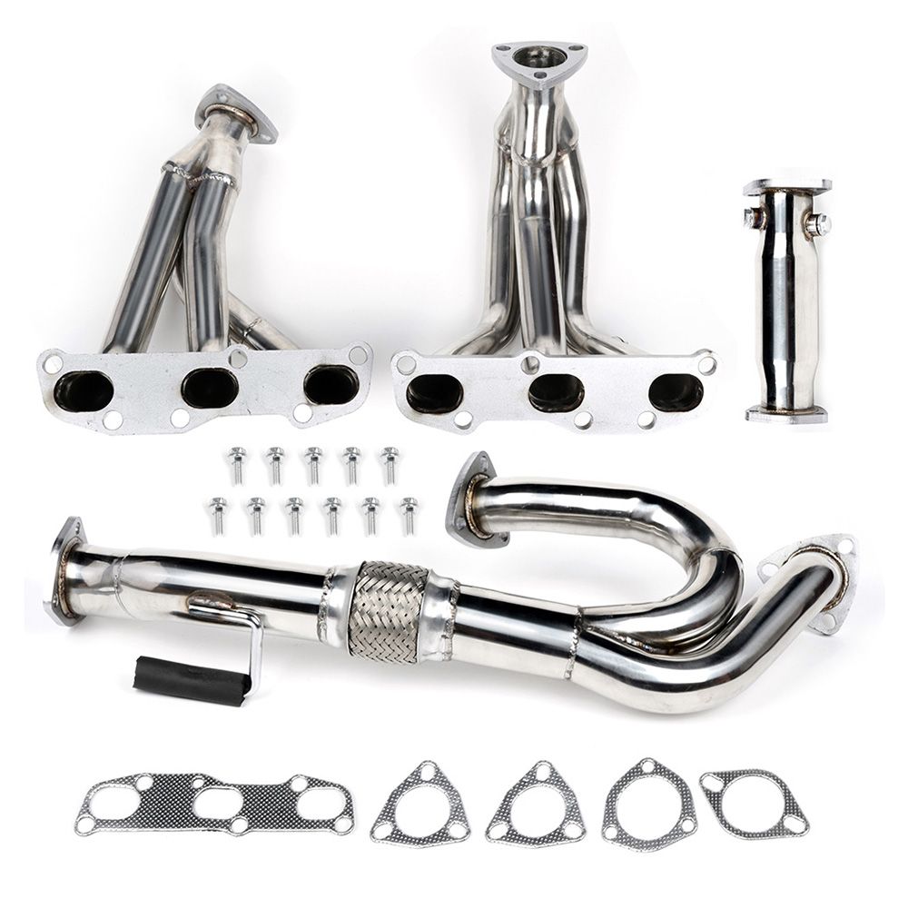
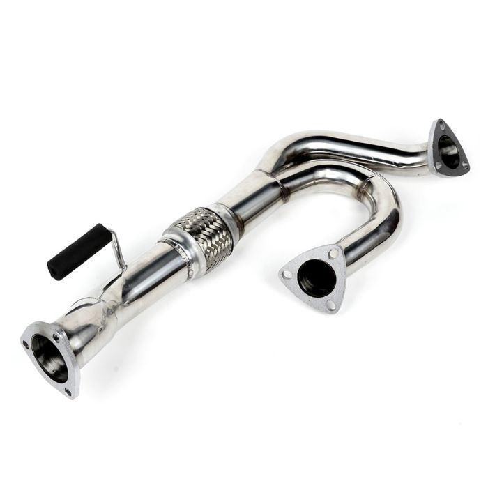
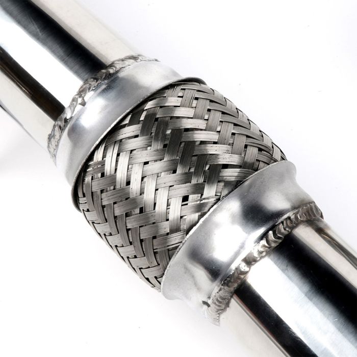
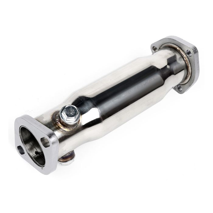
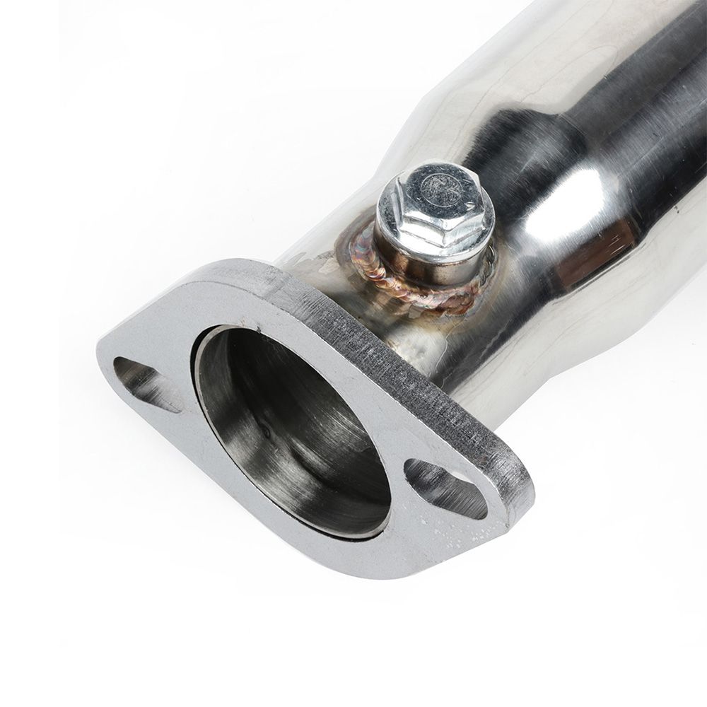
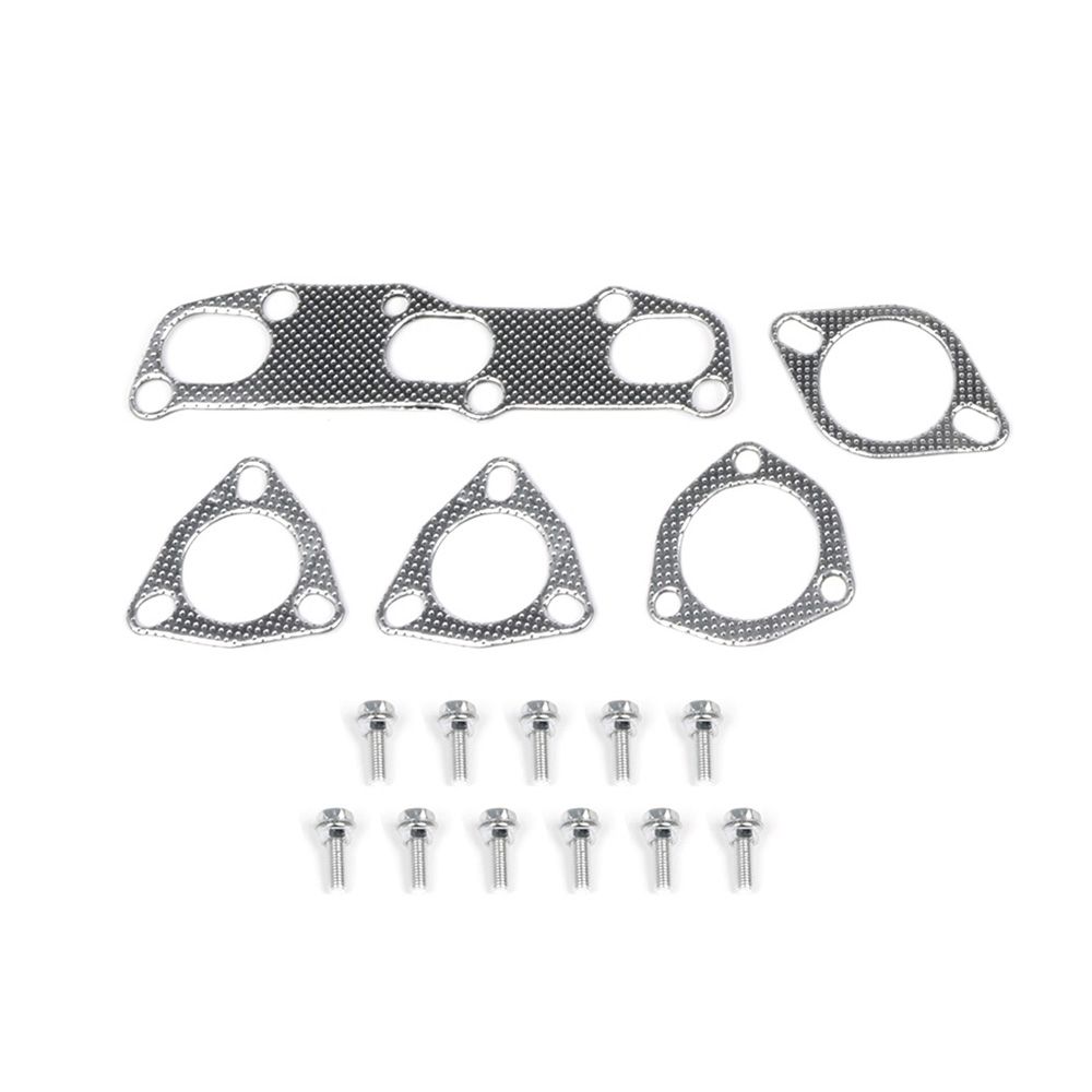
Description: 2002-2006 Nissan Altima 2.5L Exhaust Manifold Racing Header Stainless Steel
Part Number: 102233
Price: $115.74 (Shipped)
Important Note:


![]()

Owner: Felix Suarez Jr
Year: 2006
Model: Maxima
Color: Charcoal
Engine: VQ35DE
Transmission: 6-Speed Manual
Trim: SE


![]()

Owner: Jean Zelaya aka el.unfamoso.jean
Year: 2008
Model: Maxima
Color: Teal
Transmission: CVT
Trim: SL


![]()

This post is dedicated to Robert Hebert. His life was cut short on July 21st, 2021.He passionately enjoyed modifying his 6thgen Nissan Maxima and was very active in the community.
We send our deepest condolences to his friends and family. Gone but never forgotten!


![]()

Owner: Gary McNally aka Blkmagic
Year: 2004
Model: Maxima
Color: Black
Engine: VQ35DE
Transmission: 5-Speed Automatic
Trim: SL


Engine:
Suspension/Braking:
Wheels/Tires:
Exterior:
Interior:
![]()