

Last Updated: 12/10/2023 @ 10:40 am
Member Credit: Unklejoe
I purchased a used an E-Manage Ultimate a couple of weeks ago and I finally got everything installed and set up so I figured I should share my experience, as this is not a commonly used device for the 5.5 gen Maximas.
Install:
I used DandyMax’s write up for some other useful information, but his guide was for the A32 and 2000-2001 A33, so I had to do certain things differently. Link Below:
My Emanage actually came with a plug and play harness for the 350z/G35 and 04+ Maxima, but this was not compatible with my ECU, so I had to cut and splice every wire individually. I used a combination of heat shrink tubing and silver bearing solder.
Important Notes:
- I added diodes (Radioshack rectifier diodes, the black ones) on the ignition output side of the Emanage, as it is rumored that the ignition drivers inside the Emanage leak small amounts of current, which triggers the ignition coil transistors to partially “turn on” the coils. This can fry the coils due to over heating. The voltage drop of the diodes is supposed to reduce the amount of current seepage from the ignition drivers of the Emanage. This was more common for the Emanage BLUE, but I figured that it wouldn’t hurt to do it on the Emanage Ultimate also.
- As stated in DandyMax’s guide, you have the choice of running either the coolant temp sensor and the intake temp sensor, or replacing one of the temp sensors with the knock sensor. Please note if you are going to use one of the inputs for a knock sensor, set the appropriate jumper to OPEN. Not doing so will send false knock signals to the ECU. You’ll know if you are getting false knock because your car will pull about as hard as a moped.
- Please note, I was not able to get the knock sensor input to show anything, even on the newest firmware (as of September 2010) version 2.20.
- The autotune (AFR Target) feature will NOT work unless you have the coolant temperature sensor hooked up.
- You DO NOT need to have the crank sensor input hooked up in order to advance or retard the ignition timing, it is only there to be able to show you your real time ignition timing.
Problems and Solutions:
Upon doing my first datalog, I noticed random spikes/dips of my ignition timing and RPM’s and other RPM dependent functions. If I switch the RPM Input to “Ignition Coils” instead of “Crank Sensor”, the RPM spikes went away, but the ignition timing spikes were still there (this is determined from the crank position sensor). After some research, I came to the conclusion that my crank sensor wire was getting some electromagnetic interference from the engine bay.
I thought that I could fix it by replacing the Crank sensor wire with a shielded audio cable that I had laying around. Well, this did not change anything. This ruled out interference as being the problem.
After some MORE research, I saw a post on here about how someone else was getting random ignition timing spikes and they fixed it by downgrading to FW version 1.14. I did that.
This did reduce/eliminate the random ignition timing spikes, but read on…
Fried Coil Anyone?:
After driving around for an entire day with the Emanage Ultimate hooked up, I pull into a parking lot and shut the car off. Once I get back in, I turn the key to the “ON” position and put my seatbelt on.
I start the car, and I notice that I am only running on five cylinders. I limp home and determine that my center/rear coil melted. Figures that it’s one of the coils that you can’t get to without taking the entire UIM off.
I replaced the coil with a coil from PepBoys for $70 with a lifetime warrenty.
My theory is that the coil got fried because I was running the older firmware version 1.14. I upgraded back to firmware version 2.20 and I haven’t had a problem, and it’s been two days.
This surprised me actually, as I figured that I protected myself by installing the diodes, but apparently not.
Just remember to never leave the key on the “ON” position for extended periods of time, as the small current leakage of the Emanage will heat up the coils and eventually kill them.
Timing Advance (Or Not):
Once I got everything situated, I decided to do some logs to see where my timing was at.
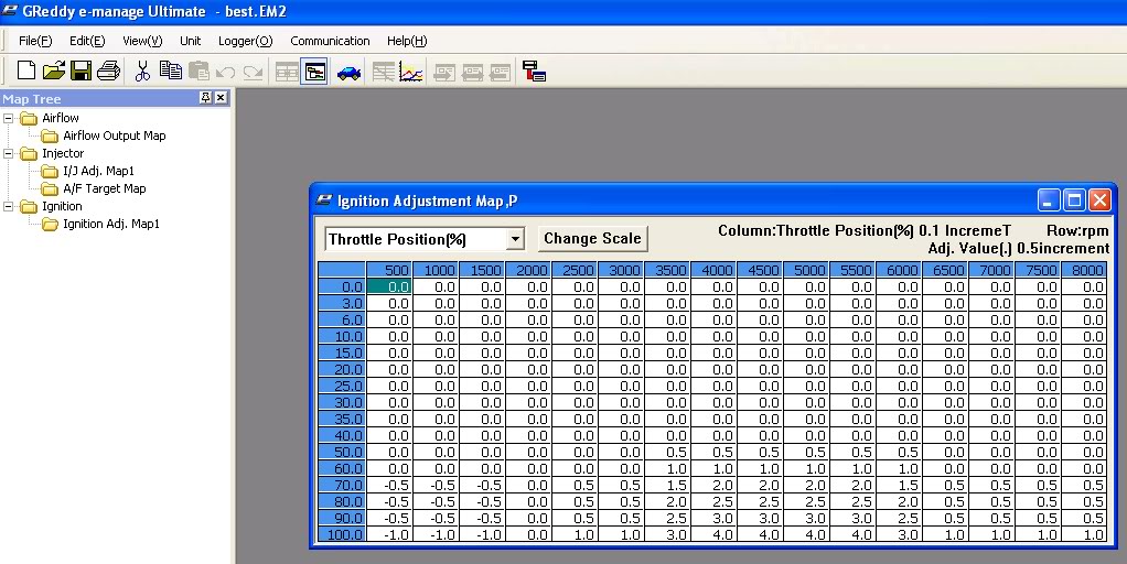
I tried adding some timing here and there, to bring my total curve average to around 24 degrees, approaching 28 as it gets closer to redline.
Well, I was able to add about 3 degrees until I noticed that for each extra degree that I added, the timing in that area ACTUALLY WENT DOWN. This was because the ECU was pulling timing because of “knock”.
I was running 93 Octane gas and I was only at like 23-24 degrees of timing and I was getting knock. This can’t be right because I’ve seen VQ30’s run much higher timing (28-30 degrees) and the VQ35 is supposed to be less prone to knock.
It appears as if the 2002-2003 ECU is much more sensitive to knock input from the knock sensor.
I temporarily bypassed the knock sensor by putting a 470k Ohm resistor in its place and I was successfully able to advance my timing to around 25-26 in the low end (1000-4000rpm), 23-24 in the midrange(4000-5000, torque peak), and 27-28 in the high end (5000-6600).
I did advance it too far at one point and I was able to actually HEAR the knock so I immediately stopped and retarded some timing. It is extremely important if you are going to do this, to do all your pulls with the windows down so you can hear any potential knocking.
At this point, I am researching ways to reduce the sensitivity of the knock sensor. I am thinking about putting some sort of rubber bushing under it to muffle some of the noises that it “hears”. I will report back with results. I don’t really feel comfortable driving around with no knock sensor. If I can at least get SOME knock protection, that would be great.
AFR Tuning:
I am using an Innovate LC-1 wideband to monitor my air fuel ratio. I did not want to buy the Greddy Option port harness for $20, so I made my own. I used one of the old cables for the audio port of a CD ROM drive in a computer (not the ide cable, the 4 pin little audio cable). I grinded the connector down so it would fit. Remember that the ground is the pin closest to the option 2 port. The positive is the pin on the opposite side.
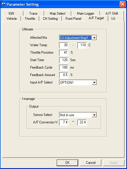
I set the AFR Target settings to activate above 41% throttle. I left the feedback cycle and amount alone.
The target AFR map is 12.9 everywhere.
I plan on leaving this on all the time, which I heard is bad but I don’t care, as it gives me perfect 12.6-13.2 AFR’s in every gear at every RPM.
Coolant Temp Problem:
I noticed that my car never quite heats all the way up. This causes the idle to remain high. I think this is due to JP13 being set to “1-2”. I will switch this to “open” tomorrow and report back.
Blown E-Manage (October 2010 Update):
Well, I did the above (about switching the jumper setting for the coolant problem), and I fried my E-Manage! Within five minutes of the car running, after I switched the jumper, it stalled out and the E-Manage’s green power LED would not come on. This is believed to be because when jumper 13 is set to open, it is expecting a knock sensor input, which is a lower voltage than a coolant temp sensor.
DO NOT RUN THE E-MANAGE WITH JP13 SET TO OPEN IF YOU HAVE A 5.5 GEN! In DandyMax’s guide, it states to try switching the jumper settings if you are having problems with your coolant temperature reading correctly, which I was, but his guide is for the 4th and 5th gen Maxima, not the 5.5 gen , which has a different coolant temperature sensor.
I had to purchase another E-Manage unit. This time I did something different. Read on…
Tricking the E-Manage:
I needed a way for the E-Manage to think that the car was warmed up so that the Autotune feature would work, but I had no way to properly hook up the coolant temperature sensor from the car. If I hooked it up with JP13 set to 1-2, it interferes with the signal and causes the car to think that it is cooler than it is, and when I switched the jumper to OPEN, I fried the E-Manage.
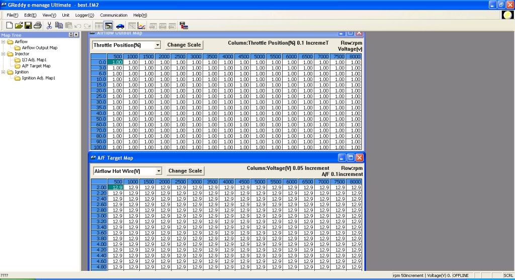
So, I discovered that when fully warm, the car’s temperature sensor sends out ~1.00 volts. I connected the AIRFLOW VOLTAGE OUT of the E-Manage to the WATER TEMP IN on the E-Manage. Then, I configured the E-Manage’s airflow correction map to output a constant 1 volt signal at all RPM ranges. This is with JP13 set to 1-2.
I am basically using the E-Manage to send out a constant 1 volt signal to itself, to trick it into thinking that the car is always warm. Now I don’t have to have my coolant temperature sensor connected to my E-Manage at all.
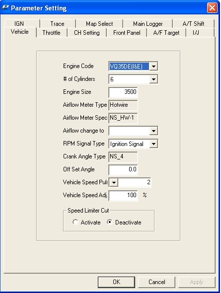
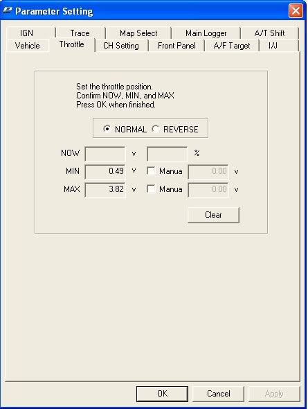
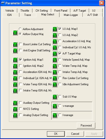
Screen Shots:
Parameter settings.

My ignition adjustment map. (Don’t just copy mine, as every car responds differently to ignition advance)
Screen shot showing the airflow adjustment map and my AFR target map.
Picture of how I wired the diodes in:

![]()

Comments are closed.