

Community Member Credit: Jeff Ketch
Installation was actually rather simple but did require some fabrication to get everything hooked up and working. Only a short piece of 3/4″ by 1/8″ steel and some aluminum angle were needed for mounting everything. However, understand that horn kits don’t ship with wiring or connectors, so plan on making several trips to the Radio Shack to get what you need. I suggest 10 or 12 gauge wire (with an inline 20 amp fuse) for the compressor circuit, while any 14-16 gauge wire will handle the switching tasks. You’ll need to tap into the stock horn wiring for the switching.
I am going to try and explain the wiring.
- The compressor has two connections. One female end on the compressor and the other end to relay #30. WIRE: female connectors at both ends.
- The other compressor connection is ground (negative…frame of the car or run an open connector to the car batteries negative terminal).
WIRE: female one end and open or circle connector on the other side. - Relay #85 to ground (negative…frame or negative battery terminal)
WIRE: Female connector on one end and open or circle connector on the other side. - Relay #86 gets a female connector and the other end is a male that plugs into the stock horn connector. The stock horn is in front of the radiator (looks like a 3″ diameter disk).
- Relay #87 gets a female connector for the relay and the other end goes to the positive battery terminal( open loop connector. Take off the nut on the battery and put the connector between it).
Relay numbers:
- 85: Ground
- 86: Stock horn switching
- 87: Hot lead that runs to the battery terminal (POSITIVE).
- 30: Hot lead running to the compressor.
Short cut for Maximas:
The relay is not necessary for the air horns to work.
- Plug a male connector into the stock horn switching, plug the other end of the stock horn switching into the bottom of the compressor (positive)
- The compressor has one more connection (negative), the negative to the compressor and the other end to the ground (car frame)
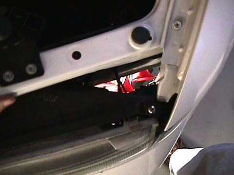
This picture is taken to show where the horns are installed. We’re looking down on top of the driver’s side headlight, and you can see the front of the horns light up by a drop light in the space in front of the wheel inside the fender.
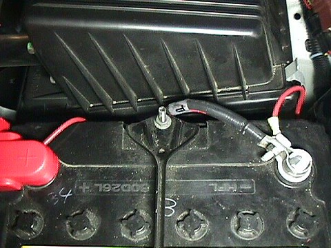
Here is the wiring that goes to the battery. Since the battery was so close, we didn’t bother wiring to a ground bolt. We used 12 gauge wire.
The horns are mounted inside the drivers side front fender, behind the fog light. Here is a picture showing the horns mounted to the strip of metal. We picked up the metal at Home Depot, they’ve got tons of it. Doesn’t have to be 3/4″ x 1/8″, anything in that range will do. Underneath the metal, you can see the support bracket that connects to the fender. This comes with the Maxima. It is too thin and also has a shape to it that wouldn’t allow mounting the horns to it.
You can also see the relay is attached using the same bolt as the horn all the way to the right. The top and bottom terminals connect to the compressor, thus the heavy 12 gauge wiring. The other wires tap into the stock horn wiring to control the relay, and don’t have to be heavy duty, so I used some extra speaker wire I had laying around.

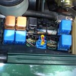
You are looking top down…between the radiator and the front grille. The picture shows the stock horn switch (black) and the wire used to tap into the stock horn. By tapping into the stock horn for switching when your factory alarm goes off it uses the air horns. Also disconnect the other stock horn that is in the engine bay on the left side.

Here’s another view of the above picture, taken from farther out. You can easily see the fender support brace here. Take the 10mm bolt out, then put the horn bracket between the support brace and the frame. This is also where I ran the ground for the stock horn.

Here is another view of how we mounted the horns.

Yet another angle. These pictures should be clear enough so that you can understand how to do this on your own.

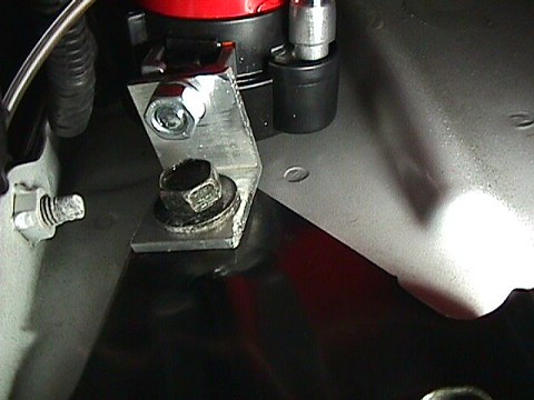
This picture is taken from the floor, looking up to see where the compressor is mounted. We used a short section of 1 1/4″ x 1 1/4″ aluminum angle to mount the compressor to the top of the shipping tie down hooks which are attached to the frame via three heavy bolts.

Here is a close-up of the aluminum angle we used to mount the compressor. Again, this was obtained from Home Depot, but be warned… the shortest length they sell is 8 feet… and you only need about an inch or so to make this bracket. If you felt adventurous, you could make the bracket by bending a piece of the same 3/4″ x 1/8″ steel that the horns mounted to.
Finally, here is a good shot of the area where the compressor mounts. The horns are at the top of the picture, the compressor mount is below the rightmost horn, and the driver’s side fog light is at the bottom of the picture.

Finished Product


![]()

Comments are closed.