

Member Credit: wariow3
This is a how-to to change the current lights in the Hazards and Rear Defroster buttons. This application is for 95-99 Maxima’s but might work also for other max’s and cars. Thanks to JackBauer for his help on the hazards and rear defroster.
Difficulty:
Easy to moderate.
Knowledge of LED’s + Resistors
Experience with soldering recommended
Items needed:
Small flat head screw driver
Small Phillips screwdriver
3mm + 5mm leds ( around 10-15, more just incase they blow or just don’t’ work) I get mine off eBay from the user ctwick or something.
He ships them from hong kong and it’s free shipping. I paid 9 dollars for 25 blue and 25 white leds. Nice and bright and they come with free resistors too!
Soldering Iron (small tip preferred) 10-15 dollars from radio shack
Soldering braid 99 cents from radio shack (use to suck up excess solder)
Tweezers
Scissors
Electrical tape
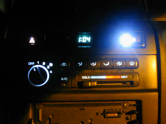
Hazards and Rear Defroster
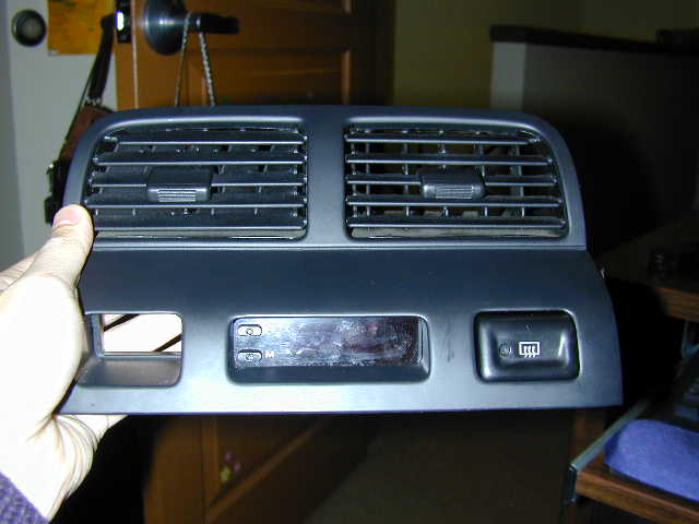
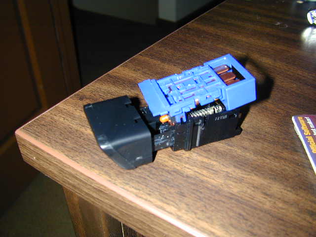
Here’s the center vent area of the dash taken out. It’s pretty simple. If you’ve ever installed an aftermarket stereo, you should be able to take this out with ease. Just pry at the bottom right corner and move to the left corner and it should pop out. Slowly pull it out. Remove the plugs from the back and bring the unit inside. Here’s a front shot of the unit. I removed the hazard already. They come out the same way.
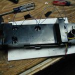
Look at the back of the unit.
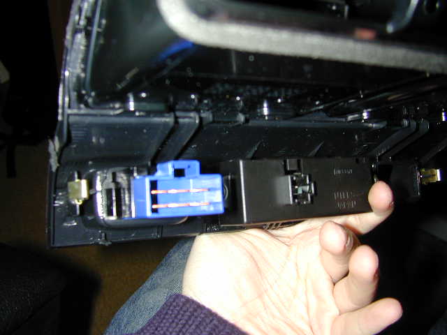
On one side of the hazard or defrost switch is a wedge.
Push this thing in with your fingers or a flat head until the unit goes in a little bit. Then with all your strength, push the damn thing out from the back.
It seems like you’re going to break something but you’re not. Just push at the base with your palm, it should come right out.
Here’s the switch. Stick your little screw driver on each and slowly pry it out.
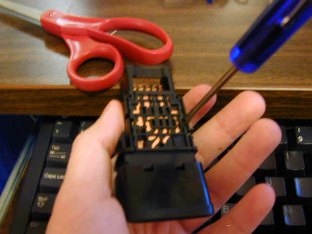
Here’s the switch apart
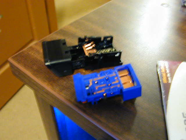
There are two bulbs for the hazards and one on the hazard. You will to replace these with 3mm leds. You will need to solder resistors on them or they’ll blow.
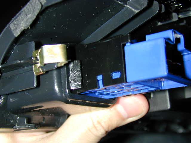
The defroster is the blue one on top and the hazard is the black one on bottom.
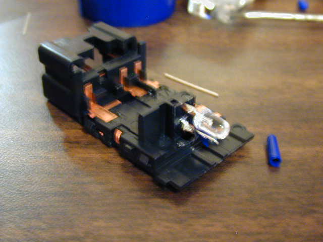
You will see that the current bulbs are in rubber housings, we won’t be using these. We will solder the LED’s with resistors right on the copper connections.
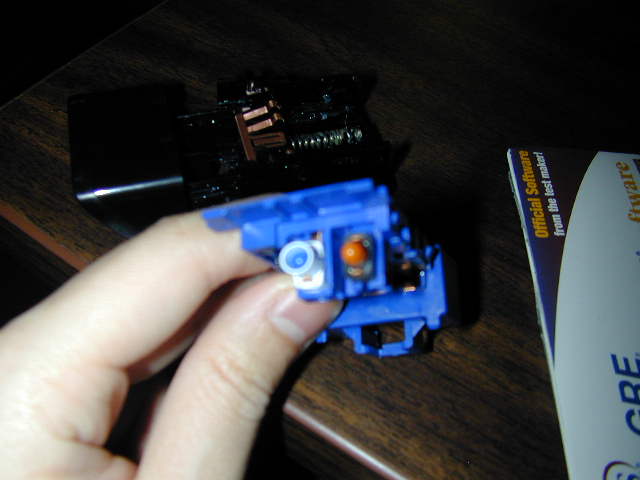
Use your tweezers and remove the housings and you’ll have the bare connections.
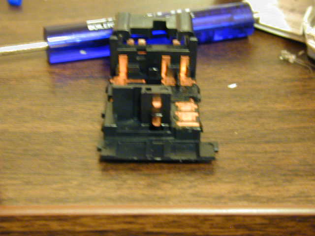
Notice the two prongs. The top prong is the NEGATIVE(-) and the bottom prong is the POSITIVE(+). They’re the same with each switch. You will need to match the connections to your LED’s. To find out which connection is positive, look inside the led. The smaller piece inside is positive and the larger piece is negative. So you will have the bigger piece with the top prong and the positive with the bottom prong.
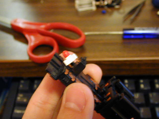
Here’s how I soldered my LED’s to my connectors. (note: I used 5mm because I did not have 3mm’s at the time, I recommend using 3mm because they are easier to work with and product as much amount of light as 5mm)
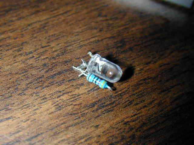
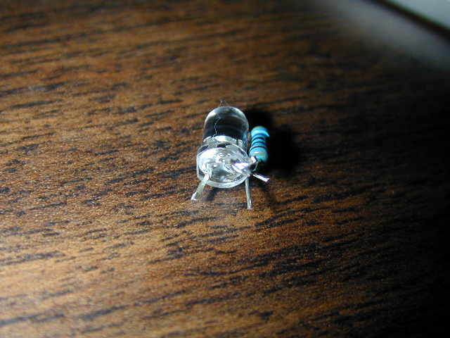
Solder the one end of the resistor to the positive side. After soldering the positive led lead to the resistor, electrical tape the part where the led connects to the resistor. We’ll be connecting the other end of the resistor to the positive (bottom) prong and the negative LED lead (the one not connected to the resistor) to the negative (top) prong.
Solder does not really stick the copper prongs so we’ll have to put solder on the prongs before putting the LEDs on. Use your soldering iron and grab some solder up and just “paint” the prongs with solder until they stick. After the prongs have some solder on it, you can solder the leds on it. Remember, resistor to bottom and LED lead to the top. MAKE SURE THE CONNECTIONS DO NOT TOUCH OR IT’LL BLOW THE LED OR CAUSE A SHORT.
Pics of it soldered on.
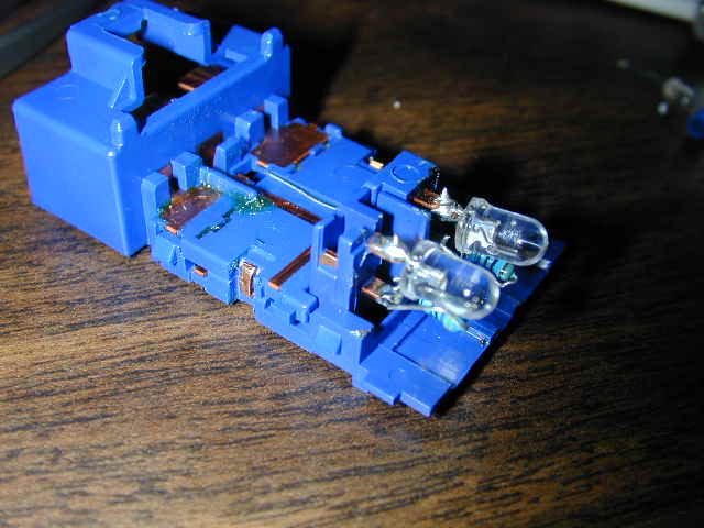
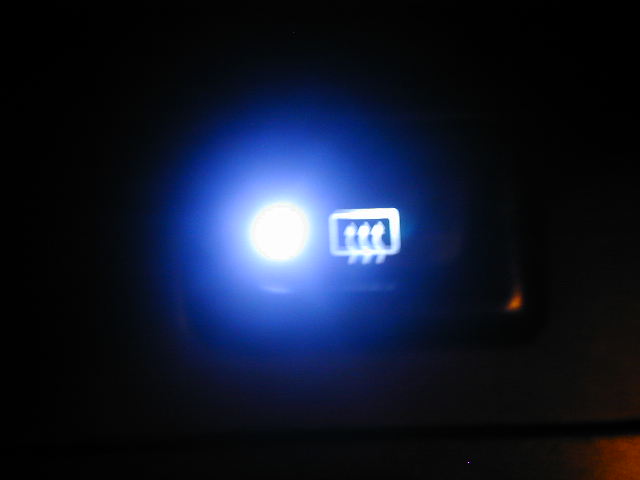
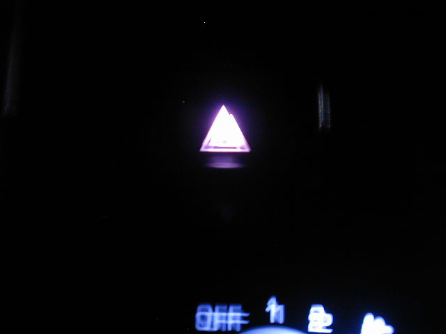
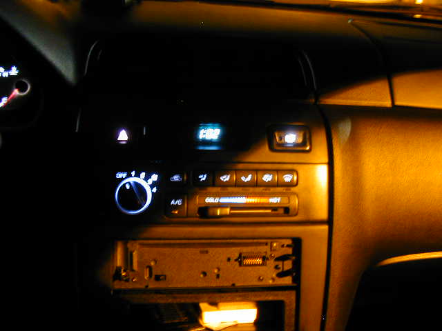
Reassemble the unit but don’t put it back into the vent piece yet. Go back to the car and test if it works. Remember: The hazard on led will work only if the ignition is switched on. If they work, good. If not, check the connections and see if they are touching or not or if the connections on the prongs have come loose. Here’s some pics of it installed.
Disclaimer: I am not responsible for whatever happens to you or your vehicle.
![]()
Comments are closed.