

Member Credit: Puppetmaster
This should work on all Cali spec Maximas. When dealing with codes P0420 and P0430, whether its voluntary removal of or just bad pre-cats, the O2 sim helps keep your SES/CEL/MIL light off and typically also prevents the ECU from storing any related codes. Rear 02 sensors only monitor if the cats work and do not affect the long or short trim fuel so basically, they do not affect drivability or the air/fuel ratio. Since the ECU is monitoring catalyst efficiency using the rear O2 sensors and the O2 sim simulates the proper voltage for the ECU to think that the cats are working. For more info, see www.o2sim.com.
Btw, I was throwing a CEL for P0037 and P0057 (I did the self diagnose procedure and counted the SES/CEL blinks) codes before, since my secondaries were completely unplugged and off the car. After installing the dual output sim and reseting the ECU (the procedure was a pain in my arse), the CEL is gone. I still have to drive it around some to make sure it stays off, so we’ll see how that works out.
And yes, my secondary O2s are just ziptied under my engine cover.
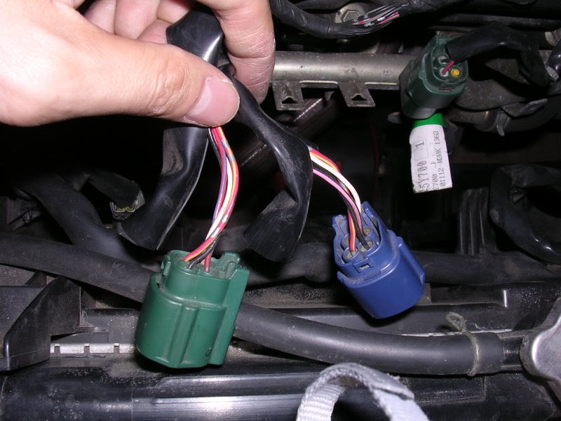
The wires tapped into are the wires BEFORE the connectors for the rear/downstream/secondary O2 sensors (so the length of wiring going from the ECM to the connectors). The dark blue connector connects to the WHITE wire shroud/harness and this is for the Bank 1 (rear bank) downstream O2 sensor. The green connector connects to the RED wire shroud/harness and is for the Bank 2 (front bank) downstream O2 sensor. Cut back the black wrap before each connector and you should see 4 wires:
Black: Ground
White: Signal
Red/Yellow: Power
Red/Blue: Heater
If you are going to simulate BOTH secondary O2 sensors, be sure to have bought a dual output sim with one black wire (ground), one red wire (power), and two white wires (signal).

The installation for a single output sim is the same, except you just tap into the signal of the sensor you want to simulate instead of both.
On ONE O2 sensor harness:
Using a wire stripper, strip about half an inch to expose the copper wires under the ground and power wires.
Tap the black wire from the O2 sim to the black (ground) wire.
Tap the red wire from the O2 sim to the red/yellow (power) wire.

Cut the white signal wire and connect one of the white wires from the O2 sim to the end that is going back to the ECU.
On the other O2 sensor harness:
Cut the white signal wire and connect the second white wire from the O2 sim to the end that is going back to the ECU.

Heater wires:
Leave em intact and both secondaries plugged into their respective connectors, the ECU still needs to read these or it will throw a code for heater malfunction or something.
You can now either solder the joints and wrap them up in heatshrink or electrical tape, or you can clear the codes and start the car to see if the sim is doing its job before soldering. The yellow LED on the sim should be blinking when the car is on/running.


Almost:

![]()


Comments are closed.