Source Credit: EddyMaxx
These are instructions on how to install a wet nitrous kit in your 6thgen. This is pretty straight forward but if you have any doubt please take it to someone who knows how to install these systems. The Zex model used for 6thgens is usually the 82016 Model. Below you will see all the items that come with it. This does now show hot to install the bottle warmers, heaters and window switch. This is for the main nitrous setup. The accessories will be discussed in the information thread with pricing.

Items Included in Kit
§ Nitrous Management Unit 1 Mounting Bolts and Nuts 1
§ 10 lb. Nitrous Supply Bottle (unfilled) 1 Arming Switch/Wire Harness 1
§ 4 ft. Stainless Steel Braided Hose, -3AN 1 Wire T-Taps 2
§ 16 ft. Stainless Steel Braided Hose, -4AN 1 Barrel Connector 1
§ Nitrous Spray Nozzle 1 Spade Connector 1
§ Bulkhead Fitting Assembly 1 Ground Ring Terminal 1
§ 1/16 NPT Tap 1 Black cable ties 10
§ 3 ft. Length of Rubber Hose (3/16 SAE30R/KY) 2 Grommets 2
§ Hose Clamps 4 Instructions 1
§ Tall Bottle Bracket 1 32 Tuning Jet 1
§ Short Bottle Bracket 1 36 Tuning Jet 1
Installation Instructions
1. Decide where to put everything. Before you drill a hole in your car, make sure you know where you’re going to install the various components of this kit. You’ll have to discover the best positions for each component by trial and error. First, the nitrous line that attaches to the engine air intake is about 4 ft. long. That means where you choose to install the nitrous nozzle decides, with a 4 ft. radius, where you have to mount the nitrous management unit (NMU). Also, you need to connect the vacuum/pressure circuit for the fuel pressure regulator to the NMU, so be aware of the distance between these components. You’ll also have to decide where to install the arming switch and nitrous bottle. The arming switch should be installed in a position convenient to the driver, but not in an area that increases the chance of unintentionally arming the system. You’ll have to run a wire through the firewall to the NMU. Do it just like you would run a lead for your stereo system. In fact, if you have one installed, you can probably run the arming lead through the same grommet. If not, try to use a wire loom hole that is grommeted. To help decide where you’ll mount the nitrous supply bottle, check the following section for technical restrictions on bottle mounting locations and positions.
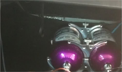
2. Mount nitrous supply bottle. Mount the nitrous supply bottle so that it is separated from the passenger cabin. Fastback style cars that do not have a separate trunk compartments have to be equipped with a safety blowdown tube. Route the tube from the safety pressure relief cap to the exterior of the car, preferably under the car. Doing so will prevent your car from filling with a cloud of nitrous oxide should the safety pressure relief cap rupture. Index the pickup tube with bottle position (Fig. A, B and C). ZEX™ nitrous bottles are designed with the bottom of the siphon tube at the bottom of the bottle towards the outlet. Always mount the bottle so that as your car accelerates, the liquid flows toward the pick-up tube.


3. Mount nitrous delivery line under the car.
When routing the nitrous delivery line under the car, try to use the sub-frame as a conduit. This protects the line and eliminates the need to use clamps. The supplied cable ties work if you can run the line higher in the under-body so that it’s safe from the road level obstacles such as speed bumps. For the pro-race look, you can use steel loom clamps with rubber sheathing to fasten the line to the body.


4. Mount nitrous management unit. Keeping in mind the length restrictions of the nitrous nozzle feed lines, mount the Nitrous Management Unit in a suitable location. Use the four screw holes provided for this purpose. It’s a pretty rugged piece of equipment that is built to withstand underhood temperatures as well as exposure to weather.
Note: I had to mount mines upside down for a better fit.

5. Install nitrous nozzle. Optimum nozzle placement is 6” to 18” from the throttle body. After you have determined where to mount the nitrous nozzle in the intake, make sure this location won’t interfere with other components. If your engine uses a mass air flow sensor, mount the nozzle after the sensor but before the throttle body. After you’ve found the spot, mark it and remove the air inlet duct from your engine. Drill a 7/16-inch mounting hole and install the bulk head fitting. Be sure to remove any drill shavings since they can severely damage your engine. Install the nitrous nozzle so that the spray is in the direction of airflow. Also enclosed is a tap should you need to mount the nozzle in a metal duct. Just drill a ¼- inch hole where you want to mount the nozzle, tap the hole and install the nozzle. Once installed, place the appropriate tuning jet in the nozzle and attach the 2-foot long, -3AN hose over the nozzle end.

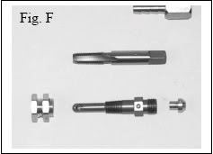


6. Install regulator and intake hoses. Measure and cut to length the two hoses that lead from the NMU’s regulator and intake hose barbs. The regulator hose barb from the UMU gets connected to the vacuum fitting on the engine’s fuel pressure regulator with one of the lengths of hose. The intake hose barb from the NMU gets connected to an unused vacuum fitting coming off the intake manifold plenum with the other length of hose. Install the fuel tuning jet in the holder as seen in Fig. G and tighten the hose barb/tube nut assembly over the top of the jet.

7. Wire it. Once you have mounted the components, you are ready to wire the nitrous system. From the Nitrous Management Unit, find a suitable ground for the black wire and connect to it with the included crimp-on ground ring. Run the red wire through the firewall of the vehicle into the interior, behind the dashboard. Ensure that the red wire passes through a grommeted hole and not a bare metal hole. The wire’s insulation may be rubbed off if put through a nongrommeted hole. Run the white wire from the NMU to the output voltage lead from the throttle position sensor. After these connections are completed, you need to install the arming switch/wire harness assembly. Find a suitable place in the interior of the vehicle for the arming switch and drill a ½-inch (.500) hole.
Mount the switch and switch cover through this hole. Take the lead that the fuse assembly is attached to and find a suitable 12 volt accessory source of power under the dash. Use the T-tap electrical connector to splice into the 12 volt accessory wire and plug in the wire harness lead. Take the other lead from the arming switch and connect it to the red wire from the Nitrous Management Unit. As a reference for wire locations, use Fig. D

8. Program activation switch and check vacuum and pressure lines. Now that you have completed the wiring of your nitrous kit, one of the final steps is to program the activation switch and check the vacuum and pressure lines. To program the Activation Switch, turn the vehicle’s ignition on, but do not start the engine. Turn the nitrous arming switch to the “ON” position. Go to the Nitrous Management Unit (NMU) and locate the push-button switch. Depress, then release, the push-button switch. Observe the NMU’s Operation Light. At this point, it should be RED. This RED light informs you that the NMU’s Activation Switch is in learn mode. Return to the driver’s seat and depress the accelerator pedal to the floor, holding it there for 10 seconds. Release the accelerator pedal and go back to the NMU and observe the Operation Light. At this point, the light should be flashing continuously from RED to GREEN to OFF. This is the NMU’s way of telling you that it has successfully learned the voltage curve of your engine’s throttle position sensor. Go back to the driver’s compartment and turn off the system’s arming switch, then turn it back on. Go back to the NMU and observe the Operation Light. It should be solid GREEN at this point. This informs you that the system is armed and ready to activate at wide-open throttle. Return to the driver’s seat and depress and release the accelerator pedal several times. You should hear the solenoid click each time you reach wide-open throttle. At this point, your Activation Switch is fully programmed and ready for use. If you ever transfer your nitrous system to another vehicle, perform this same procedure on the new vehicle to “relearn” the NMU’s Activation Switch. To ensure that the system is ready to be used, a final vacuum and pressure check of the system’s hoses and lines must be done. With the engine running, check your “intake” and “regulator” hoses for any vacuum leaks. Generally a vacuum leak will cause the engine to run rough. Assuming the vacuum lines check out, open the nitrous bottle valve. Listen carefully to your engine as the valve is opened.
You should not hear a difference in idle speed or engine sound. If you notice either of these changes, call our NITROUS HELP™ line at 1-888-817-1008. If there is not change in idle speed or engine sound, shut the engine off at this time and inspect the nitrous pressure lines and fittings for leaks. Leaks in the nitrous supply line will be obvious because they will be covered with frost.
9. Check fuel quality and ignition timing. The last thing to do before enjoying your new nitrous system is to ensure that premium fuel (92 R/M Octane or better) is in the fuel tank and that your ignition timing is set correctly. All recommended ignition timing retard amounts on the Tune-Up Sheet are calculated off of the base, stock ignition setting. It is important to set this with a timing gun before you use your nitrous system for the first time. Do not assume that it is set properly. If the ignition timing is not set correctly, severe engine damage may occur.
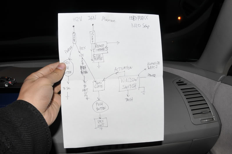
10. Window Switch Diagram (Only if you plan are using one)

ZEX™ #82016 Tune-Up Sheet

Premium quality fuel, 92 R/M octane or better, is required at all times for safe operation of your ZEX™ Nitrous System.
WOOHOOOOOOOO!!!!!!!!!!!!!!

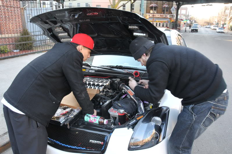
Just chilling…The Beast from the East!!!

It is the responsibility of the installer to ensure that all of the components are correct before installation. We assume no liability for any errors made in tolerances, component selection, or installation.
![]()


Comments are closed.