

Member Credit: wariow3
Difficulty:
Moderate.
Knowledge of LED’s + Resistors
Experience with soldering recommended
Items needed:
- Small flat head screw driver
- small phillips screwdriver
- 5mm leds ,I used white LED’s( around 4 or more, one for every gauge, more just incase they blow or just dont’ work) I get mine off ebay from the user ctwick or something.
- He ships them from hong kong and it’s free shipping. I paid 9 dollars for 25 blue and 25 white leds. Nice and bright and they come with free resistors too!
- Soldering Iron (small tip preferred) 10-15 dollars from radio shack
- Solder
- Soldering flux ( to help stick solder to smooth-surfaced connections)
- soldering braid (to clean up excess solder)
- Tweezers
- Scissors
- electrical tape
- thin probably 20-22 gauge speaker wire
- wire stripper
- medium grit sandpaper
Gauges
REMINDER: This will work best with a 97-99 dash. If you have a 95-96 you MIGHT be able to do it but I haven’t tried it so it’s up to you.
You also need to do the 194 bulb conversion for the 97-99 mod.
You can do this mod first and then start the LED needle mod.
This is necessary because we will be drawing power from the bulb light connections.
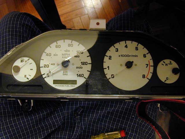
Start by removing the black plastic trim around the gauge by sliding the tabs off the white piece.
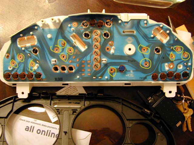
here you see the black trim is removed and the gauges and the back are exposed. Make sure not to mess around with the needles, so handle it carefully.
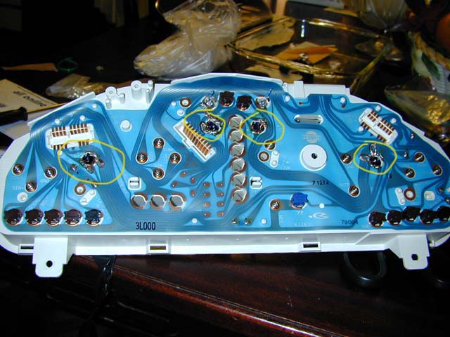
Remove the screws that attach the gauges to the cluster by unscrewing the screws with a screwdriver in the yellow circles. (most of the screws are removed in the picture) Remove each cluster carefully EXCEPT for the odometer(the one that tells you how fast you are going not the tachometer which reads the RPMs)
To remove the odometer, stick a small flathead in the wedge of the black connector and pry up to loosen the connection. After that is done, gently remove the gauge.
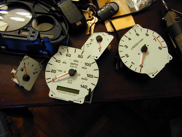
Here are all the gauges removed.
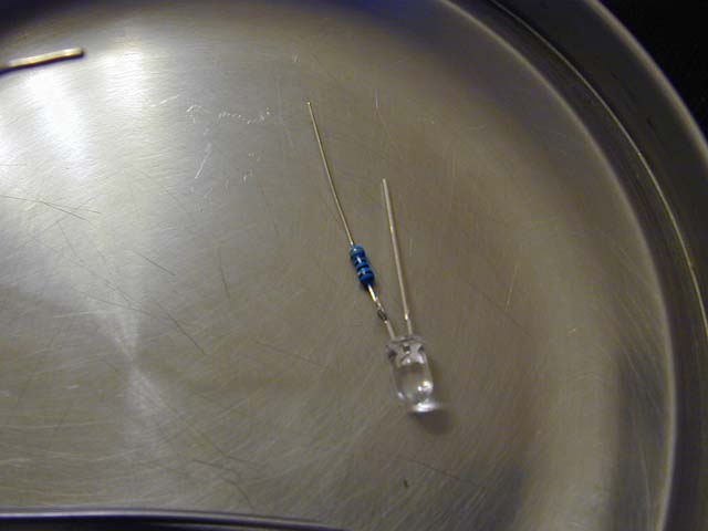
Start making your resisted LED’s. If have LED experience or did any of my how-to’s then this shouldn’t be difficult.
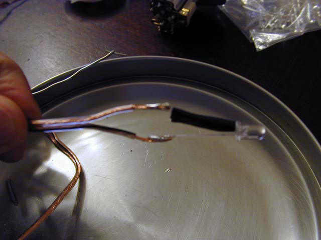
Add the speaker wire connection to the LED’s and solder those on as well give around a foot length of wire. Electrical tape one side fully then bind both sides after one side is fully wrapped.
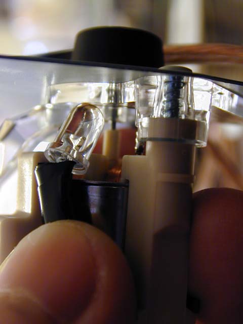
Here’s the tricky part, placing the LED’s behind the gauges. As you can see in the picture, I bent the LED a lil bit to angle it towards the plastic trim but also careful not to get in the way of any fragile mechanisms. after I am satisfied with the placement, (get the LED to point at the center as close as possible) I secure it with some more electrical tape around the gauge
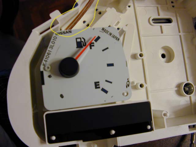
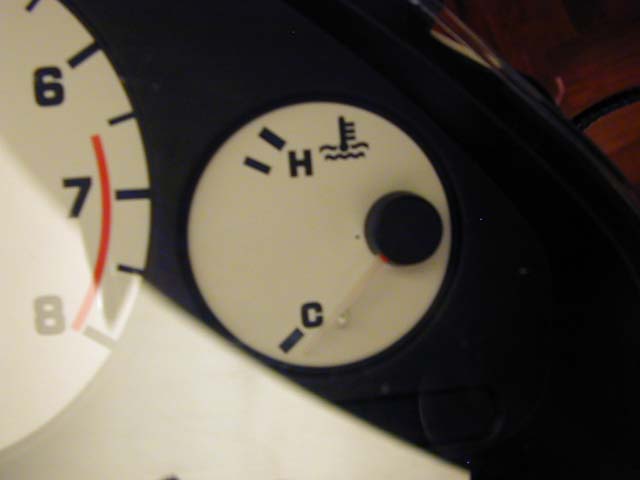
The fuel and temp gauges were the easier of the gauges because there weren’t many objects in the way and just wrapped tape around the edges.
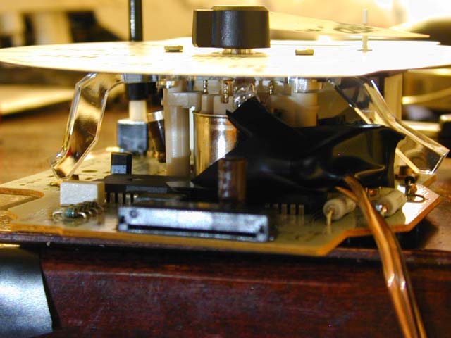
In this pic is the arrangementfor the odometer. Look at all the crap going on in there so there was only really one place to set it and taped it down to the surroundings, again make sure you won’t affect the operation of the gauge itself.
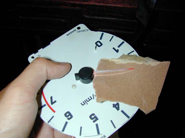
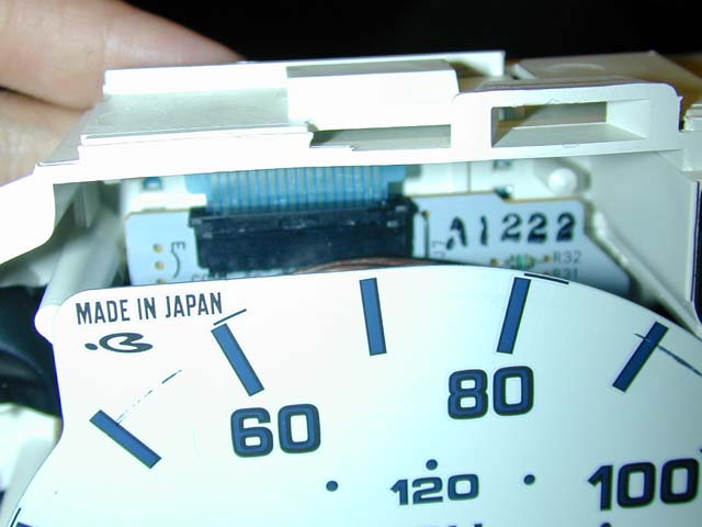
After all the LEDs are pointed correctly and are secured, using medium grit sandpaper, sand from UNDER the needle to remove the red/orange film underneath the needle to make it clear.
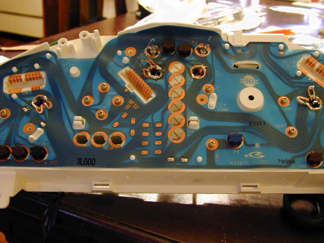
Now we’ll want to make the connections using the existing bulb connectors in the yellow circles.
Before putting back the gauges in the cluster, round the speaker wires neatly through the nearest hole of each individual gauge and then screw back on the gauge.
After each wire is pulled through each hole and each gauge is screwed back on, (REMEMBER the Odometer connection, where you have to put back in the tab. Putting this back in can be a lil tricky but try to get it as inyou can, you can tell when the tabs on the side are touching the black connector and then simply push it down to secure the connection.) it is time to solder on the connections.
Here the connections are soldered on. Make sure the are secure and well soldered. Use soldering flux to easily stick on solder to the copper connections. Remember that the 194 bulbs are soldered on also so make sure they have a secure contact with the same solder also. (NOTE: if you have a 95-96, You might be able to draw power from the twisty thing that holds the 194 bulb. Just stick the wires underneath and twist it onto the connection. If somebody attempts this, please let me know)
After checking all the connections, it’s time to finally test! Go out and plug in the gauge, remember to plug in the dimmer switch also or the bulbs won’t light up. If an LED or two doesn’t light up, try reversing the connections around and check the soldering. You might not see much during the day but at night, it’s a big difference from the red you used to have.
Nice clear needles
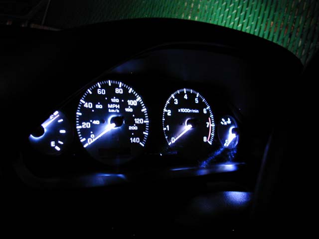
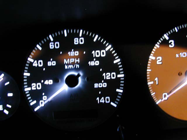
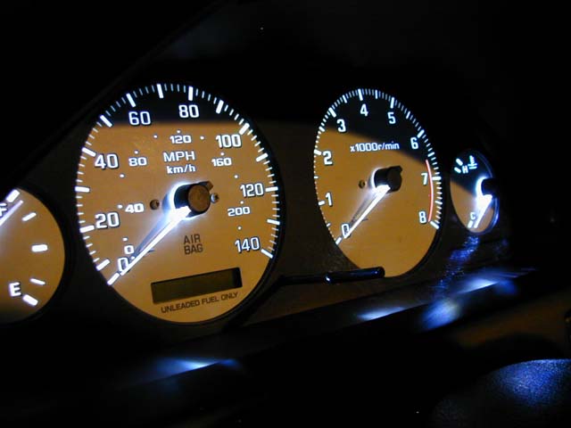
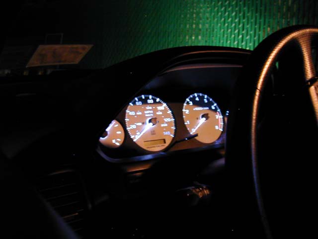
The finished results. Orgasmic if I don’t say so myself. Not that difficult to do if you have some LED knowledge and some common sense. Saved myself 50-70 dollars on intelliglo needles also.
Total price of mod: less than $5
![]()

Comments are closed.