

Member Credit: twin001
This write-up is for a 2003/2004. But the same steps are application to 6thgen Maxima. Also, for 7thgens you do not need brackets but the installation instructions still hold.
This DIY will take you through the basic steps to remove the existing brake components (calipers, rotors, lines) in order to install the Akebono brake kit that is standard on the G37S and the 370Z Track model (I think it’s called “Track”..can’t remember).
I wanted to note one more thing, you don’t to completly purge your brake fluid for this installation. I needed to change mine out, it had been a year and a few track events so it was time for replacement. You can simply disconnect the lines and cap them, just make sure to bleed the system when you get everything put back together.
First, I weighed the Akebono kit at work.
- Adapter Brackets, front left and right: 1.8lbs
- Hardware, front: 2 lbs (reuse existing rear hardware)
- Front Calipers: 10 lbs each
- Rear Calipers: 5 lbs each
- Front Rotors (14″ Stoptech Slotted): 27lbs each ()
- Rear Rotors (13.8″ OEM blanks, vented): 18lbs each ()
I will weigh the existing components next week and update this thread to show the delta in both unsprung and rotating mass.
Some tools needed for the install:
Floor jack and jack stands. I used stands for the front of the car and my floor jack to raise the rear via the rear differential.
- Basic set of sockets, wrenches. A 7/8″ socket was required to remove the bolts on the front caliper.
- Tin snips, dremel, cutoff wheel or equivalent to remove/cut dust shields.
- Vice grips
- 10mm open ended wrench (Akebono calliper bleeders)
- Flathead screwdriver
- Rubber mallet
- Bowls and tubing to bleed brake system (I used 1/8” aquarium line)
Onto the install:
Break all lug nuts loose, raise car, remove wheels and set aside. You will have access to the existing rotor and caliper now.
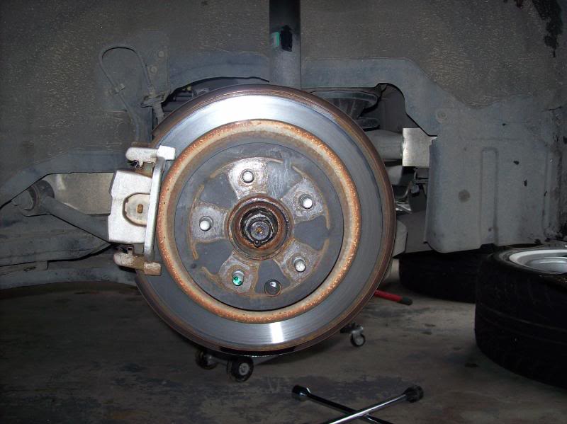
Front rotor/caliper

Rear rotor/caliper
Set up some bowls/cups (whatever works for you) under each caliper and drain brake fluid. Attach the tubing to the bleeder screw and slowly open the screw.
Rear drain setup

Front drain setup

I used the Motive 0107 bleeder to flush the brake system

Be very careful with brake fluid, it is highly corrosive and will eat through your clear coat and paint in a short amount of time.
Front caliper fluid drained

Rear caliper tubing

Rear caliper drained

Do this to all four corners. I started passenger rear, drivers rear, passenger front, then drivers front until all the fluid was evacuated from the system.
I bought stainless steel brake line with my kit, if you are using the OEM lines then ignore the next few steps.
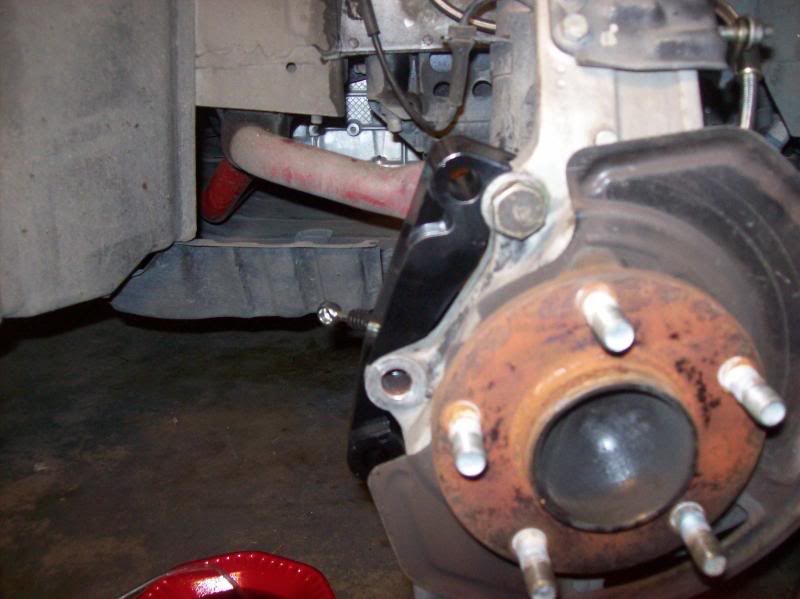
Break loose the two bolts attaching the caliper. I used a 7/8” socket for these. If you have never removed these then it would help to spray some PB Blaster/WD40 on them and let them sit for a while.

Remove the two 12mm bolts securing the OEM lines to the strut.
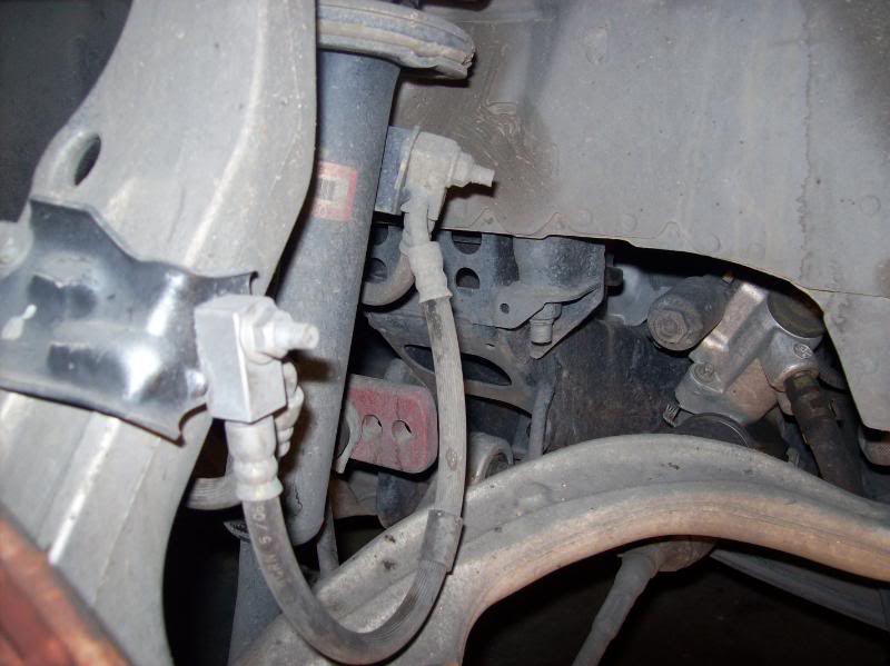
This is a tricky step, remove the clip that holds the OEM brake line to this bracket. There was quite a bit of dirt and debris in there, I used a small flathead and worked around the clip until it came out. I used a small pair of vice grips to loosen the nut.

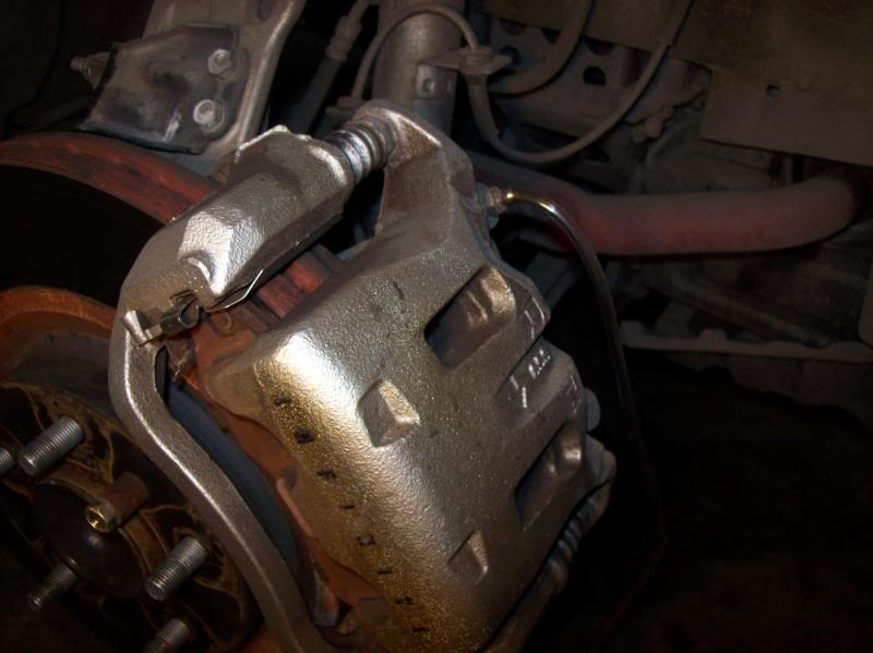
Now that the two caliper attach bolts are broken loose and the lines are unhooked, simply slide the caliper off the rotor. You may need to rock it back and forth a few times for it to come loose. Here’s one of the front calipers off the car.

Now it’s time to remove the rotor. You may need to break out the rubber mallet for this one. Nothing like banging loudly on your car at midnight! Rotor removed and off the car.

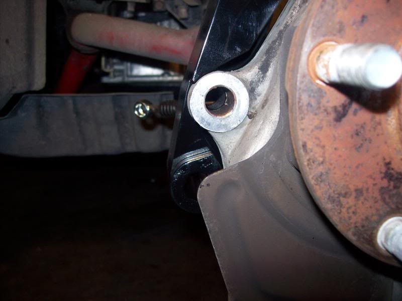
Now we have a clear shot of the dust shield. You MUST trim or remove the shields to get the new BBK to fit. I initially wanted to remove the shields but they are sandwiched in between the spindle and the main suspension components. I was able to remove 4 of the 5 17mm (I think) bolts, the last one I could not remove. This said, it was time to start hacking as much of the dust shield off as possible! You can get by with trimming a little, but I wanted that thing gone! If dirt or debris gets into the rotor it should be able to find its way out pretty easily.
This is one of the tabs that will get in the way (lower front)
Closeup of dust shield on
Dust shield trimmed to my liking.
Here’s the OEM front rotor next to the Stoptech rotor.

Do this for both front brakes. Now it’s time to go work on the rear brakes!
Again, if you are re-using your existing lines then skip this step. Loosen the nut attaching the flexible brake line to the hard line using a flared wrench or vice grips (same as front, except there are no attachments to the strut….much easier!)
Remove two 19mm bolts attaching the rear caliper to the car. Again, if you have never removed them then let them soak in PB Blaster or WD40. (Sorry, no good pics of this.)
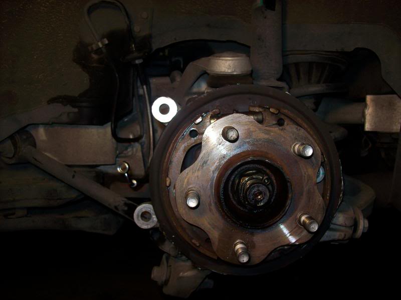
Here’s where you get to bang on the car VERY violently. Make sure you release the parking brake first. The rear rotors seem to get stuck harder than the front rotors. I sprayed around the 5 bolts and hub with PB Blaster and let it sit a few minutes then started hitting it with the mallet. Hit the rotor along the back side, actually the dust shield. Also hit it along the outer perimeter of the rotor. Eventually (after a good 15 minutes for me) the rotor broke loose.
With the rotor removed we can start hacking away at the rear dust shield. The rear dust shield has an out ring that must be trimmed for the new larger rotors to fit. Again, I cut as much of the shield off as I could.
Rear dust shield hacked to pieces!
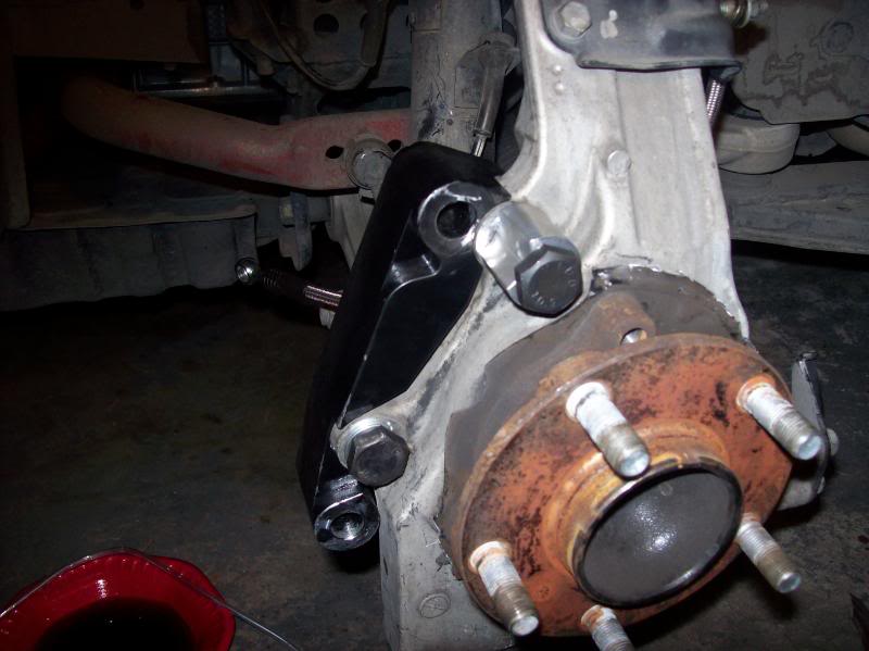
Now it’s time to look at the front brackets to attach the Akebono calipers. Unfortunately there were no instructions on how to install these. I looked at some pics online and it helped a little. The COZ bracket kit comes with four machined parts, two large brackets and two moon shaped pieces. After trying different combo to fit here is what works:
Now, the tricky part of this is to get the moon shaped piece aligned just right…there isn’t much room for error on this. If it is not aligned right then the upper caliper bolt holes will not line up. Here is what I eventually did after a few failures. With the rotor off the car, attach the large bracket as show. Then attach the moon piece, but do not tighten down. Attach the Akebono caliper to the bracket. Now, align the moon spacer so that the upper caliper bolt hole aligns with the caliper bracket and install bolt to secure calipers. Now that the caliper is secure and in place, go ahead and tighten down the moon shaped spacer. Remove the caliper and install the rotor.

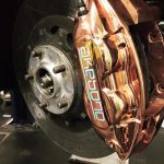
Now that the front rotors are on it’s time to build up the calipers. The kit comes with grease, pads, shims, pins, clips, cotter pins….everything you need. I didn’t take pics of
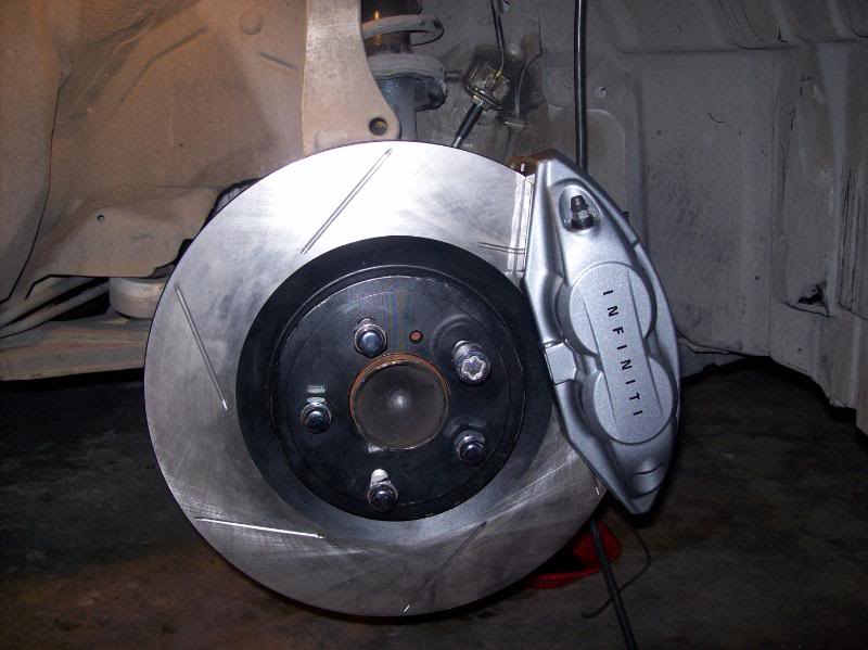
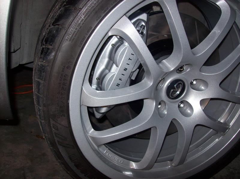
The build up because everyone was asleep and my hands had shim grease all over them. Here’s the front caliper on the car.

The front was a tight fit, hopefully it will loosen up a little after some driving. Now, install the caliper to the adapter bracket.
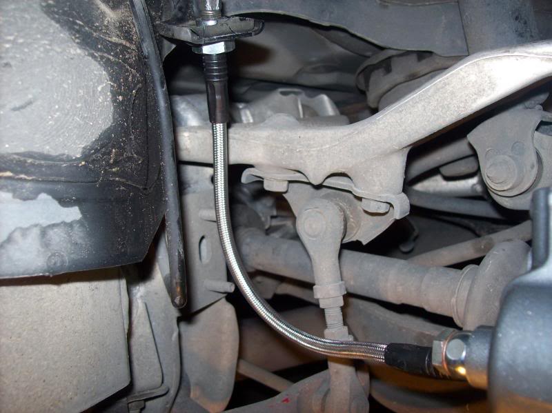
Attach the new brake lines to the caliper, 14mm bolt. No pics, but it’s pretty much error free.
The rear calipers are much easier to install. Build up the brake pad/shim/clip assembly and put in the caliper. Reuse the existing 17mm bolts to attach the caliper to the car.
Caliper/rotor on car,
Pad build up

Brake line installation
Now that everything is installed it’s now time to refill the system with brake fluid, reinstall the wheels, lower the car and brake in the pads. Make sure to lower the rear of the car first and put some tire chucks behind the tires before you lower the front so the car won’t roll back.
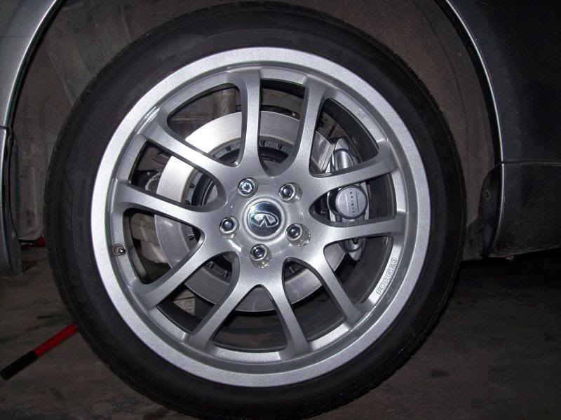
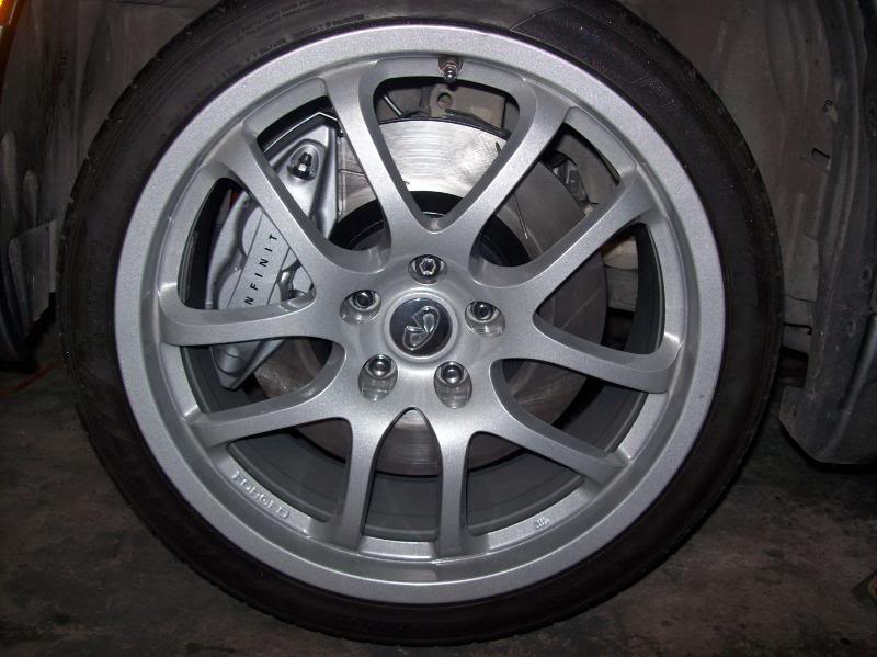
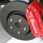
Here’s a few pics of mine installed.

Updates:
So I went for a quick drive around the neighborhood today. The pedal was very squishy and I had to pump the brakes to get adequate pressue to stop the car. Went home and checked all my lines, no leakes. Then I got to looking at the rear calipers. I had them installed with the bleeder screws facing down……BAD IDEA! (this is why you don’t work on cars at 2:00am!). I switched the rear calipers so the bleeder screw was on top, bled the system and drove again. Wow, what a change. The pedal is much more firm than stock. I am going to bed the brakes this afternoon sometime.
If you try to bleed the brakes with the screw at the bottom you will entrap some air in the top of the caliper. Always have the screw at the top so the fluid occupies the bottom of the caliper and fills its way to the top, releasing the air out of the system.
![]()
Comments are closed.