

Member Credit: myer84
I finally finished installing my last mod. For a while I’ve been searching for a shift light indicator, but nothing as big as a Monster Tach or anything that would make the car look ricey. My idea of a shift light was something that would be small and inconspicuous.
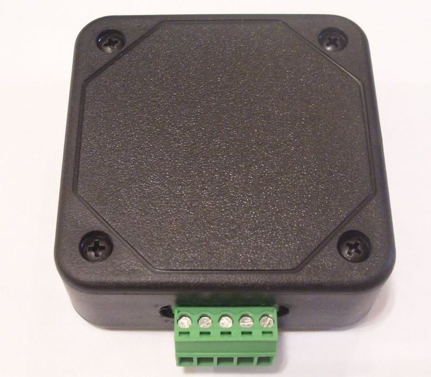
I came across a shift light module from Raptor Performance that allows you to connect a single L.E.D or more. The module is small and can be hidden under the dash and the L.E.D or L.E.D’s can be mounted anywhere in the car. With this module you can have a shift light that is not noticeable and does not take up any space or block your view like a monster tach.
Here are the instructions on how to install the shift light. The total install time was 1 hour and quite simple.
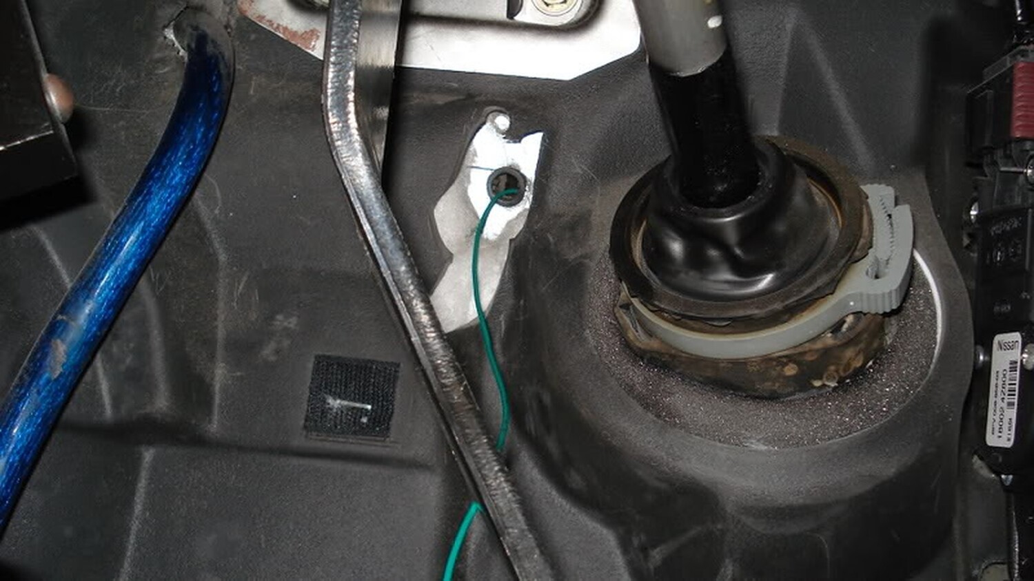
The green wire connects to the tach signal. In our cars this can be found at any ignition coil. Each coil has three wires running to them. Each coil has a red and black wire and the third wire is of a solid color with a stripe. Below is the color configuration for each coil
(coil driver #1 ) —–> Brown/Red stripe
(coil driver #3 ) —–> Blue/Red stripe
(coil driver #5 ) —–> Pink/White stripe
(coil driver #2 ) —–> Green/Red stripe
(coil driver #4 ) —–> Grey
(coil driver #6 ) —–> Grey/Red stripe
In my install, I went with coil # 6
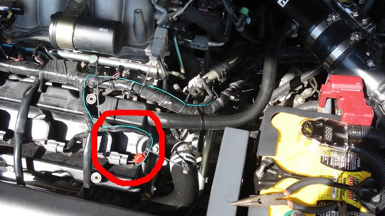
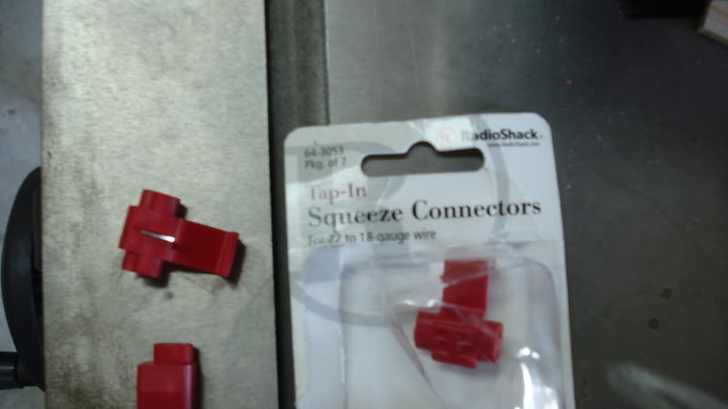
I tapped the Grey/Red wire with a 22 AWG wire tap and ran a 22 AWG wire into the cabin.
Once I finish running the other end of the wire through the firewall, the next step was to find a 12 volt source and ground. For my 12 volt source I choose the fuse for the rear power sockets
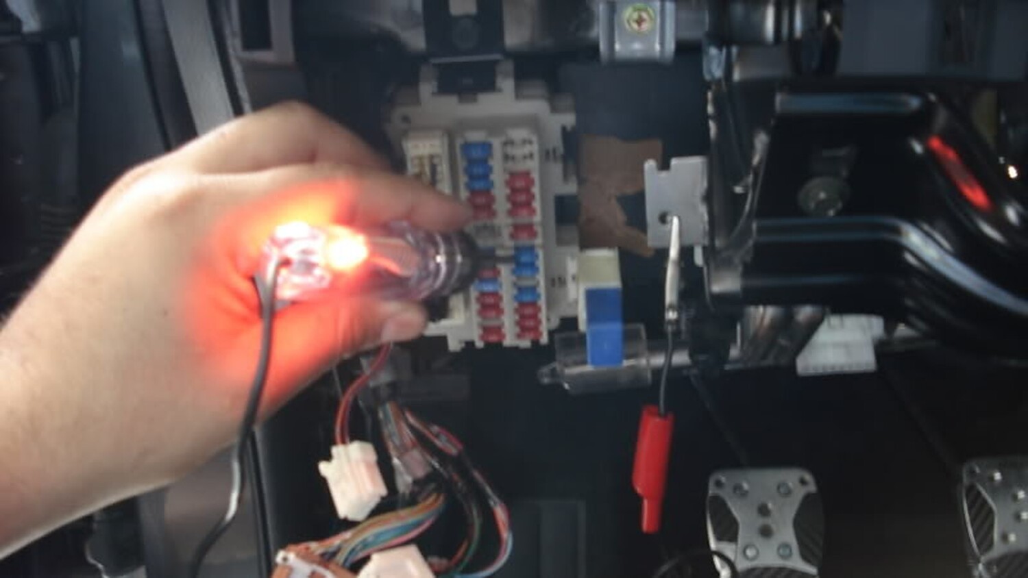
In order to use that same fuse I added a fuse tap
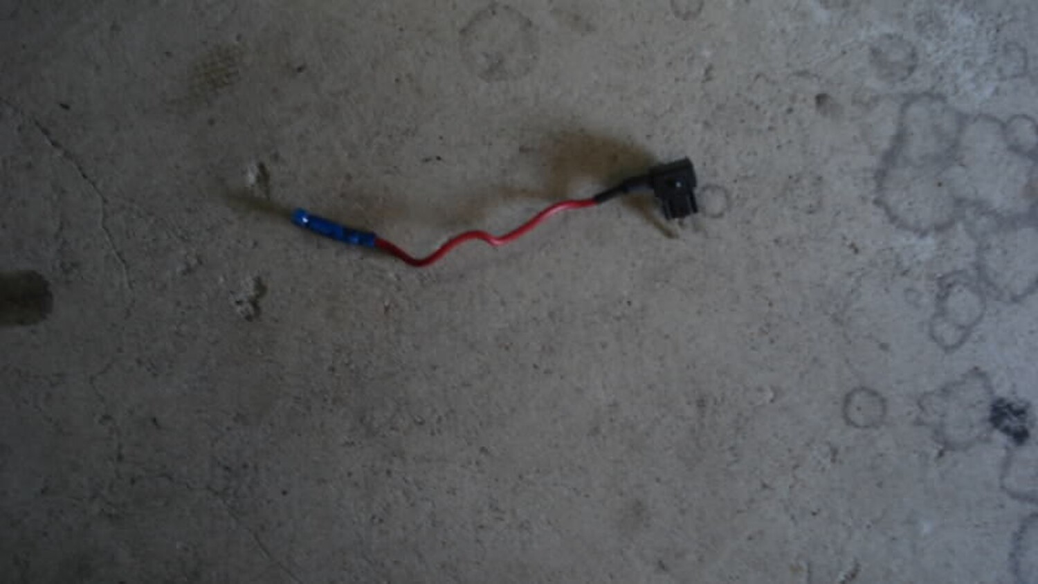
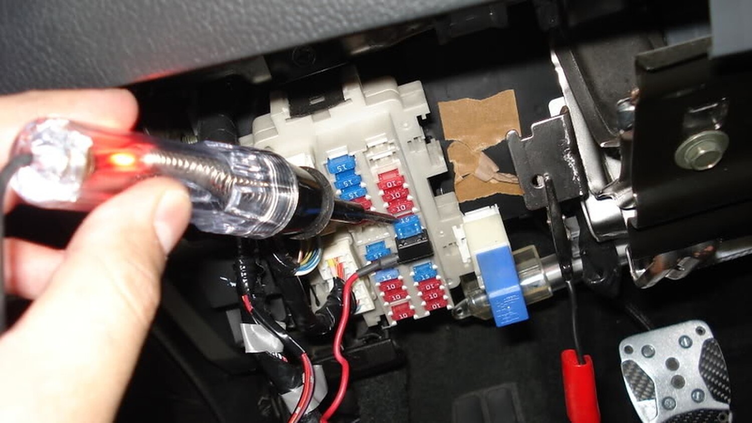
The tap has two slots to add fuses. One slot is used for the original fuse to work with the rear power sockets and the other is used for my new 12 volt source (tack module). Next step was to find a good grounding point
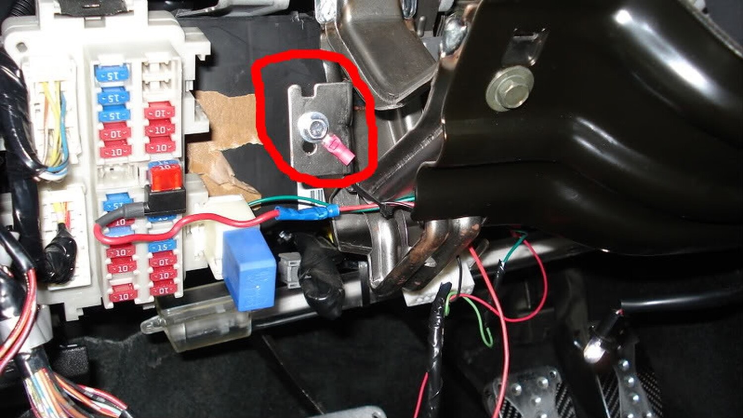
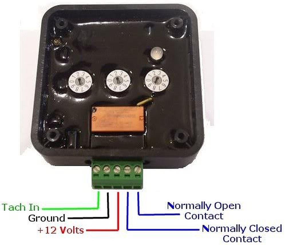
Now with the ground, 12 volt source, and tach signal connected we can now tap these wires into the harness that comes with the module. The harness has a green, red, and black wire. Green is for the tach signal and of course red for 12 volt and black for ground. The L.E.D ground will connect to the Normal Open Contact (see below ).
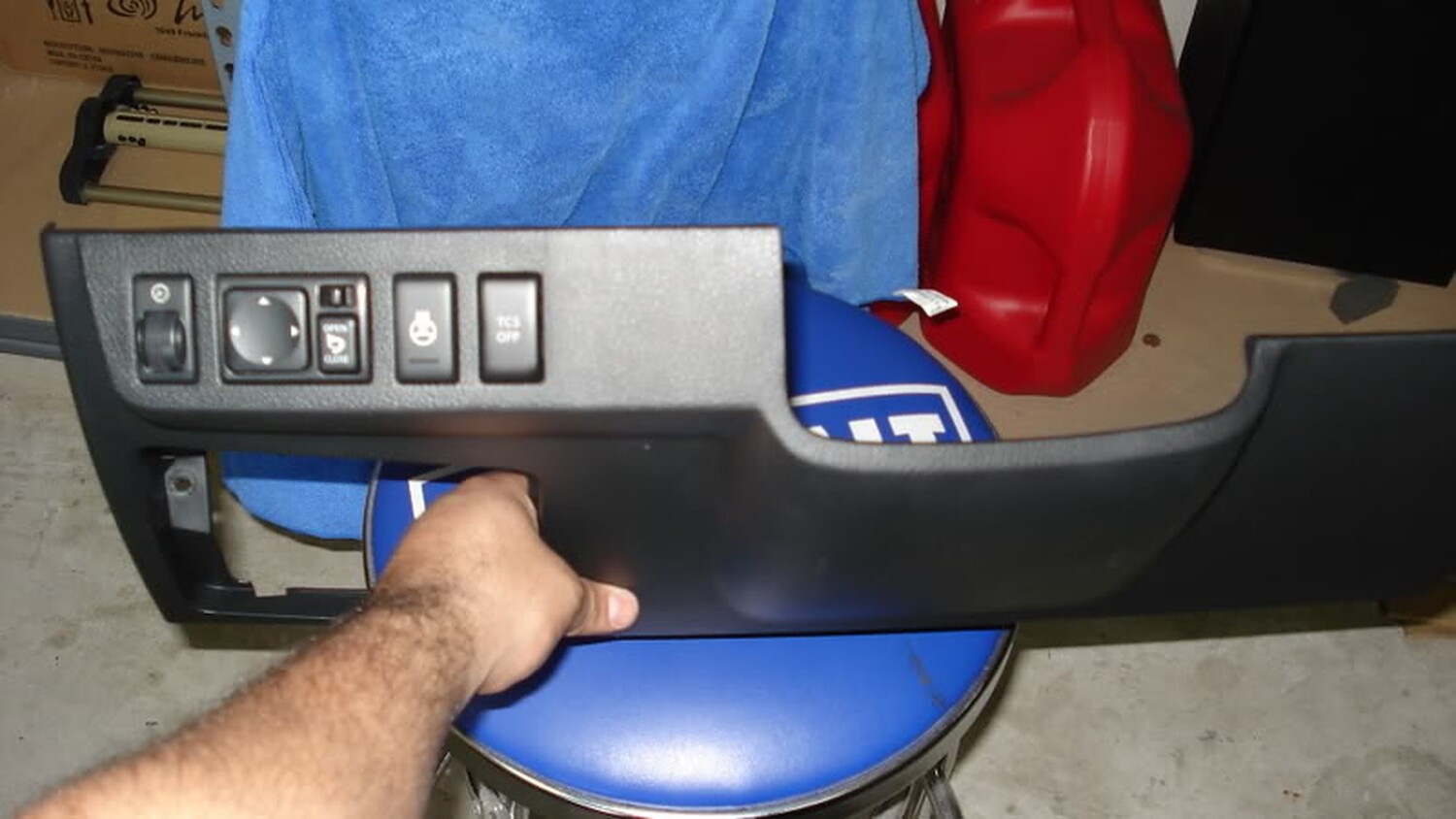
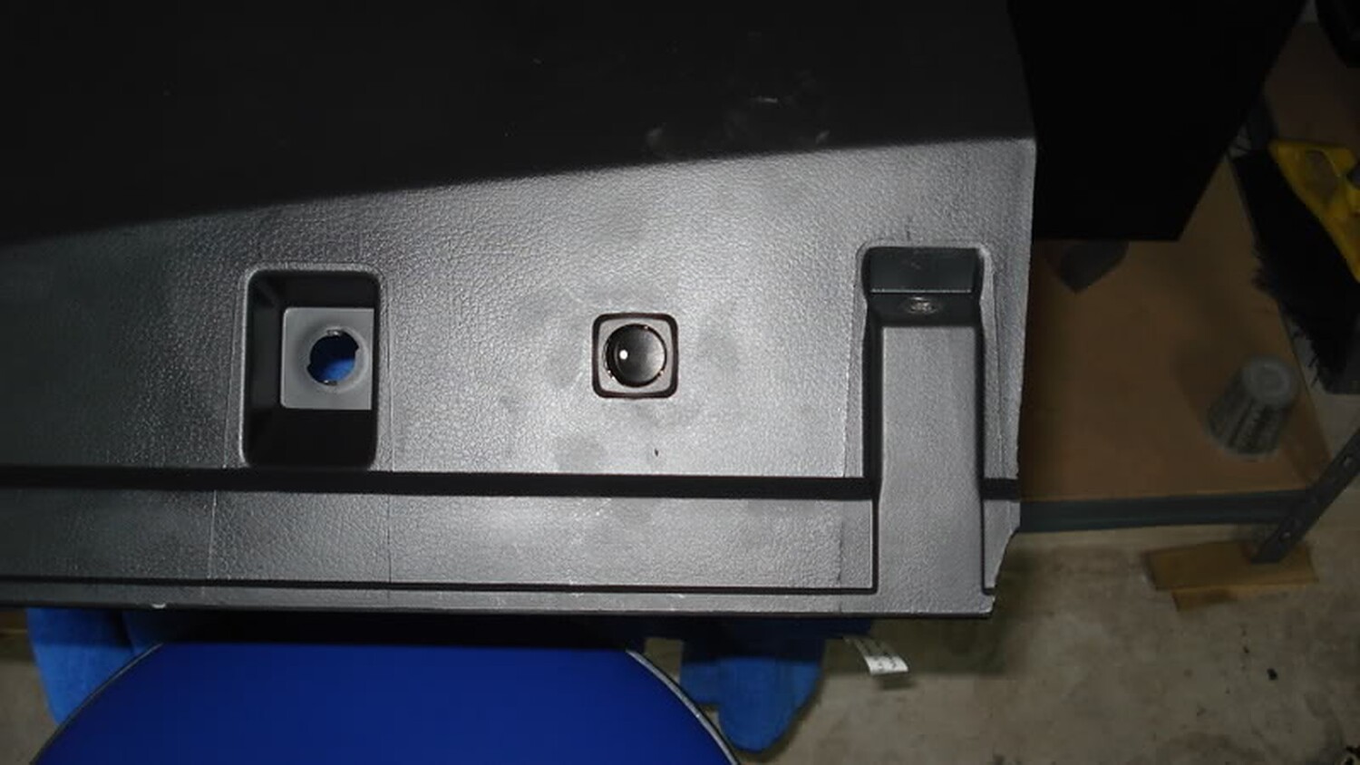
Now with the ground, 12 volt source, and tach signal connected we decided to install a switch so that I can turn on and off the module. I mounted the switch on the bottom of the panel below next to where the courtesy bulb connects. The 12 volt source from the fuse box connects to the switch and from the switch to the module.
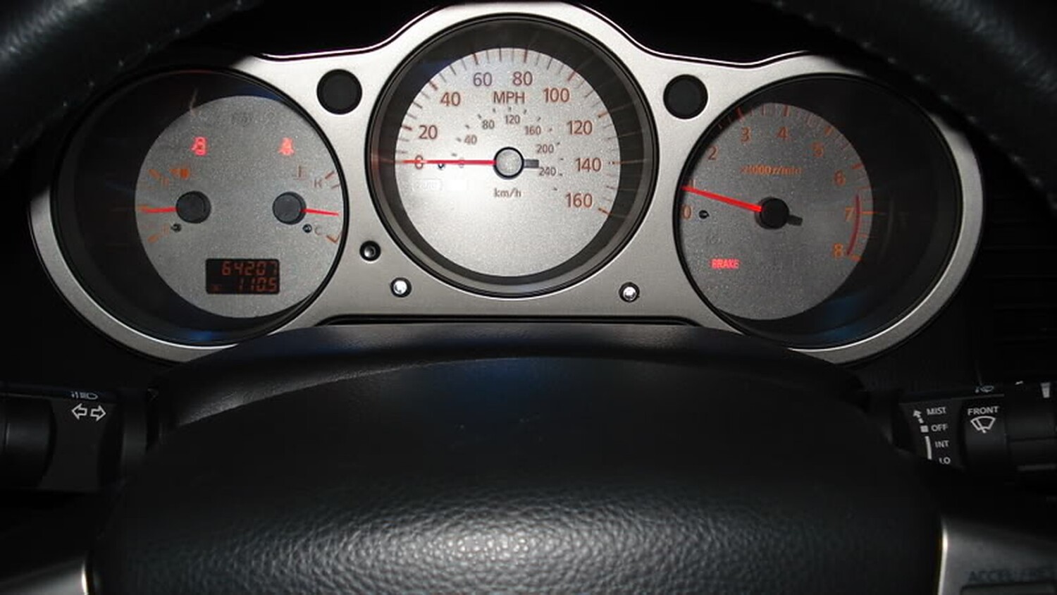
The next step is to find a spot where you want to mount your L.E.D’s. The spot I chose was on the bezel that surrounds the odometer and tach. To connect the L.E.D’s you can connect the + wire to the 12 volt tap we are using for the module and the ground you will need to connect on the Normal Open Contact.
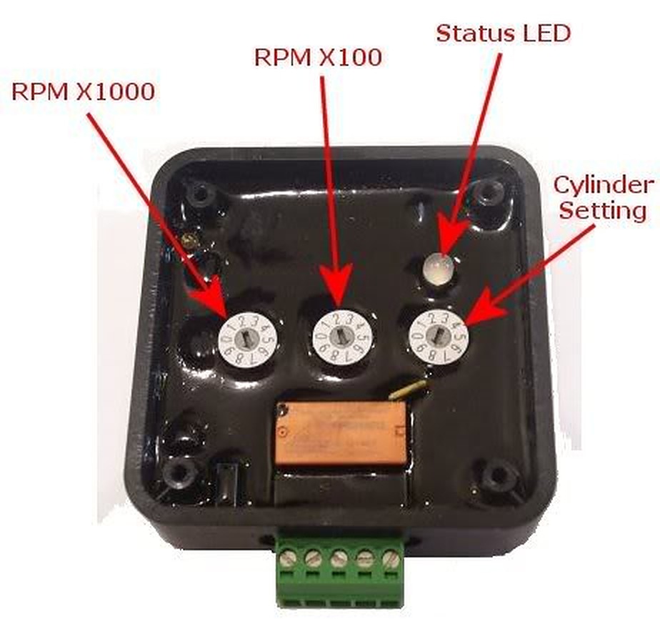
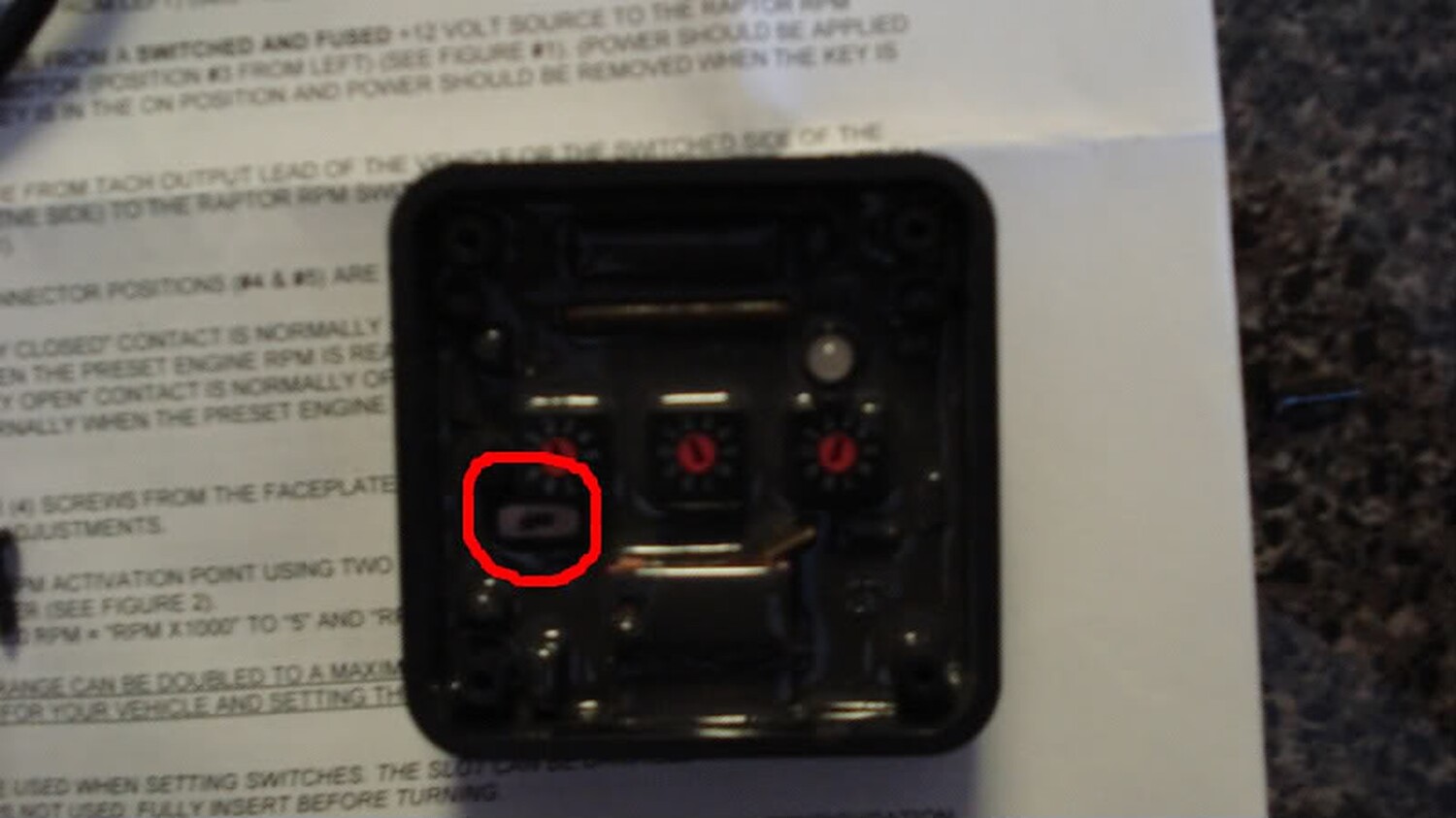
Now that we have all of this installed we can now adjust the dial on the module to your desire settings. In my case I wanted the module to send the signal to the L.E.D’s when the RPM would hit 6,100k. At 6,100K the L.E.D should light up and give me enough time to react and shift before redline.
To do this I set the RPM X 1000 at 6 and the RPM X100 at 1. This gives me a dial of 6,100 RPM. If you want to do 6,500 you would set RPM X 1000 at 6 and RPM X100 at 5. Since we are only using one coil lead in our install you will only leave the cylinder setting at 1 on the dial. You will notice that there is a small toggle switch on the module. This switch was installed on the module in order to read a low volt signal from the coil.
Once you set your signal point on the module hook the harness to the module and turn on your ignition.
If the rpm switch isn’t picking up a signal after you program it (noted by rapid green LED flash), slide the small slide switch to the alternate position. Also, make sure your power switch is also on the “ON” position. If the install was done correctly you will see the following
- A: The status LED will turn yellow and will flash the number of times which is representative of the RPM X 1000 setting
- B: There will be a pause for about two seconds (no status LED flash)
- C: The status LED will turn red and will flash the number of time which is representative of the RPM X 100 setting
- D: There will be another pause of two seconds (no status LED flash)
- E: The status LED will turn orange and will flash the number of time which is representative of the “cylinder setting” (in our case 1), and finally the module will do an LED test (alternating red & yellow) and be ready for use.
Once this is done close you module with its cover and install anywhere under the dash. I installed mine with double sided tape. Clean up the mess and enjoy.
Here is a video of how it works on my car. BTW, I want to thank my other half for helping me record the vid.
![]()


Comments are closed.