

Last Updated: 11/20/2019 @ 10:47 pm
Member Credit: maxiiiboy (Vol.4, Spring 2017)
Summary
The 5th Generation Maxima is a very reliable car – if you know how to maintain it. The problem is that the car suffers from a few design defects that can make it expensive to maintain. For example, a worn-out engine mount may damage the Engine Control Unit (ECU) resulting in a major inconvenience and a dealer repair bill of $2,000-$4,000. Other actuators may fail with similar effect, sometimes repeatedly.
This note describes these problems and the remedies for eliminating them. The remedies are inexpensive and easy to do. If you own a 5-Gen Maxima, I strongly suggest that you do the following as soon as you can:
- Implement “Coolant Bypass”, or replace your Idle Air Control Valve (IACV), or both.
- If your car has an Automatic Transmission, then disconnect your two electronic engine mounts, both front, and rear.
- Replace fuse #58 (15A, labeled ENG CONT1) in “Fusible Link and Fuse Box” by the battery with a 7.5A fuse.
Do the above even if your car experiences no problems at this time. If your car already experiences problems such as P0505 or damaged ECU, then read this document before attempting any repairs.
The above instructions may not make much sense unless you understand what the problem is. The next section describes the problem, and the subsequent one explains the remedies in more detail. If you own a 5.5-Gen Maxima, keep reading but you can dismiss the IACV issue – your car does not have an IACV to worry about.
Problem Description
The fundamental problem is that in the 5-Gen Maxima the Engine Control Unit (ECU) is not properly shielded from the failures of some components it controls. For example, we know that the ECU can be damaged by a) Failed/shorted IACV, and b) Failed/shorted Electronic Engine Mount. There are also some reasons to suspect that failure or misadjustment of the TPS (Throttle Position Sensor) may have a similar impact; I am still investigating.
How the IACV Fails
Most often, the IACV fails after the engine coolant1 shorts the wiring in its stepper motor. There is an O-ring gasket that should prevent the coolant from getting into the IACV, but after 10-15 years, it tends to fail. I suspect that there are other reasons why the IACV fails. For example, the thermo-valve inside the IACV may get stuck, or there is an intake leak; the IACV then tries to correct and eventually fails. The bottom line is that IACV failures (code P0505) are reasonably common and that they have disastrous consequences.
1 Engine coolant circulates through the Throttle Body and IACV to eliminate potential starting problems in cold weather. However, this seems unnecessary as the TB/IACV is nicely hidden between the two engine banks. There are multiple posts on maxima.org that confirm that there are no starting problems with coolant bypass, even in Minnesota winters.

Figure 1
Figure 1 illustrates how the damage occurs. With a healthy IACV, the resistance of each IACV half-coil is 22 Ohms. Together with other factors this limits the maximum current through each half-coil to 0.5-1.5 Amp, and to a maximum of about 3-3.5 Amps through each of the two ECU ports and the STA509A transistor behind each port.
When the coolant eats up the insulation, the coil shorts, and the resulting current – up to the 15A limit imposed by fuse #58 – will flow through the IACV and “fry” the ECU. The 15A fuse should blow out, but usually the STA509 driver transistor in the ECU burns first, sometimes taking adjacent components with it. Appendix A shows how a damaged ECU looks like.
The horror story does not end here. Typically, the result is that both the IACV and the ECU are damaged. If the owner replaces just one of the two parts (say, just the ECU), he will find out that his new ECU is immediately damaged by the IACV he hasn’t replaced yet!! Even Nissan dealers are known to have made this mistake! The bottom line is: Make sure both parts are OK before replacing either!
Failure of the Electronic Engine Mount
5-Gen Maximas equipped with an Automatic Transmission have two Electronic Engine Mounts (Rear by the firewall, and Front by the radiator). Figure 2 shows the wiring schematic for these two mounts. Again, failure of either mount can damage the ECU in the same manner that the failure of an IACV can.

Each electronic mount has two states – Firm and Soft. Normally, the ECU puts the mount into the soft state at low RPMs (below 1000 RPM) and into the Firm state when the engine runs above 1,000 RPM. Disconnecting the mount eliminates the danger of ECU damage. It has no effect on the car (no codes or SES light) apart from occasional vibrations; more on that in the “remedies” section.
The Remedies
The ideal remedy would protect the ECU by using onboard fuses on all its critical inputs and outputs. However, I rejected this approach because of its risks: adding components to the ECU board and cutting traces or modifying wiring is just too dangerous for the average Maxima owner. For the same reason, I also rejected any solution that would cut/modify the Engine Room Harness.
This left me with the remedies described below. All of them have been successfully tested by the author.
Remedies for IACV Failures
There are three remedies that will reduce the probability of an IACV failure:
- Preventative IACV Replacement. It seems that most IACV’s fail at around 100-120k miles. To replace your IACV, you have to remove the Throttle Body and unscrew the four Phillips screws holding the IACV. This is not a pleasant task, as the screws tend to be frozen. Once the job is done, a new IACV (use OEM part only) should be good for another 100K miles or more.
- Coolant Bypass. Coolant Bypass (see figure 3) eliminates the possibility that your engine coolant will eat on your IACV wiring. On a 2000 Maxima, the bypass requires no additional parts – neither hoses nor clamps – apart from a good set of hose pliers. The job can be done in about 5 minutes (excluding the access/re-assembly time), with the Throttle Body in place. When you do the bypass, remember to blow out any residual coolant so that the IACV is as dry as possible. Also note that in a departure from figure 3, you can completely remove the IACV “half-hose” leaving the two coolant orifices on the IACV open.
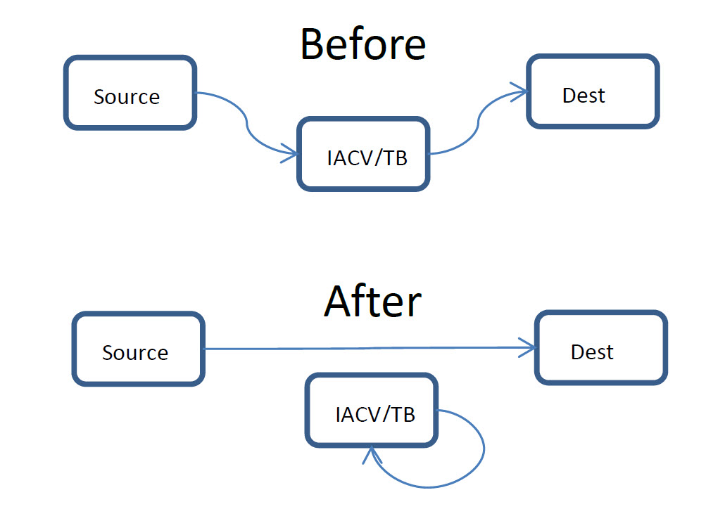
Implementing Coolant Bypass: No Parts Required, Just Move the Hoses Around Figure 3. - ENG CONT1 Fuse Replacement. Replacing fuse #58 (15A, labeled ENG CONT1 in the Fusible Box next to the battery) with a 7.5A fuse provides an improvement over the OEM setup. Be aware that the 7.5A fuse does not guarantee protection: The STA509A transistor can be damaged by any current exceeding 3A (see footnote2), but the fuse needs to be larger than 3A because there are multiple devices on it3. However, going with the smaller 7.5A fuse increases the probability that the fuse will blow before the STA509 transistor will, and it decreases the probability of large-scale damage – such as burned traces – to the ECU board itself! The fuse costs a few cents (http://www.delcity.net/catalogdetails?item=77075) and can be swapped in/out in 30 seconds.Important Note: If/when the 7.5A fuse blows, you need to treat it as a signal that your IACV has failed. You should check the IACV, and if indeed shorted, replace it.
To summarize, there is no reason not to do #3. The same applies to #2. So, the question is: After you are done with (#3 + #2), should you do #1? I have done it eventually when my IACV experienced other problems (needed cleaning).
Isolating Engine Mount Failures
Only AT Maximas have Electronic Engine Mounts. For these cars, the following remedies exist:
- Disconnect Electronic Mounts. Disconnecting the Electronic Mounts is the quickest solution. The connectors are brown, each with 3 conductors, and both are located close to the AT dipstick. Depending on whether the mount is disconnected in Firm or Soft state, you may experience the following side-effects:
A: Mount in Firm State: Some/minor vibration when the engine idles.
B: Mount in Soft State: Minor in-line vibration between 1,800 and 2,400 RPM, when the engine pulls, only under some conditions, depending on how you step on the gas. I suggest you do not worry about the Firm/Soft state too much: once disconnected, the electronic pump within the mount will stop firming up the mount, and the mount is bound to become (semi)Soft no matter how you disconnect it. - Replace with Manual Mounts. Using the mounts from MT Maxima is possible. It is also relatively easy as the MT mount is a direct fit. This is the preferred solution when the original mount is physically worn out. The side-effects are the same as in (1a) above.
- Add a Fuse to the Mount. It is physically possible to add a fuse to your Electronic Mount. The logical place is at connector terminal #3 where the battery power comes in (see figure 2). However, this would be best done when the mount is being replaced. Otherwise, #4 below may be a better choice.
- Non-ECU Control of Electronic Mounts. Yet another solution is to keep your Electronic Mounts, but take the ECU out of the loop. One would have to implement a semi-intelligent control that is both fuse-protected and decoupled from the ECU (or any other expensive part). I am tinkering with this solution.
2 Each of the two IACV half-coils is powered by a single STA509A transistor within the ECU. Each transistor can withstand a maximum current of 3A in steady-state mode and 6A in pulse mode. The desired protection would insert two fuses – one into the lead/connector port #2, and one into port #5 of the IACV (see figure 1). It would allow for proper fuse sizing, somewhere in the 3A-6A range for each fuse.
3 Powered off this fuse are multiple subsystems: IACV, EGRC1, MAFS, TP/SW, and others.
Repairing vs. Replacing Your ECU
ECU failures are annoying and expensive. When the ECU can’t be repaired, the only solution is to purchase a “new”4 ECU and then tow the car to the dealer to have the keys reprogrammed. In some places, you may be able to find a locksmith that can do this task but it is not clear this is always possible. The key point is: because of the hassles associated with key reprogramming, you always want to repair your ECU rather than replacing it.
4 “New” means “appropriate ECU of the same type, in working order
The following outfits provide ECU repair and are considered reputable:
- AvPro ECM in Fort Meyers, FL (http://www.avproecm.com/nissan.htm). These guys will not only repair ECU, but also they will also improve it by adding fusing protection. All this for $250, with 2-3 day return and a lifetime warranty. I have talked to them, and they know what they are doing (Update 7/19/2016: It appears these guys are no longer in business).
- Module Repair (http://www.shop.modulerepairpro.com/Engine-Computer-ECM-Nissan-Maxima-htm) will repair your ECU for $199.- and ship it back within two days. They advertise the same service on eBay for $99, so make your choice. They are rated 4.5 stars on Yelp.
- Automotive Scientific (aka ASI) http://www.autoecu.com/electronic-control-unit-ecu/nissan/maxima-infinity/repair-service-nissan-maxima-engine-powertrain-control-module-3-0/
This is a larger outfit that will repair your ECU (and many other electronic components) for $149. - Foreign Auto Computer Repair, Big Sandy, TX. (http://www.foreignecurepair.com/Nissan.htm). ECU repair for $250.
Reputation questioned: Circuit Board Medics.
Acknowledgments
Directly or indirectly, many members of maxima.org (and Nakis in particular) contributed to this note. I have learned a lot from other MAXIMA.ORG members. This note is an attempt to re-pay some of my debt.
Appendix A – How a Damaged ECU Looks Like

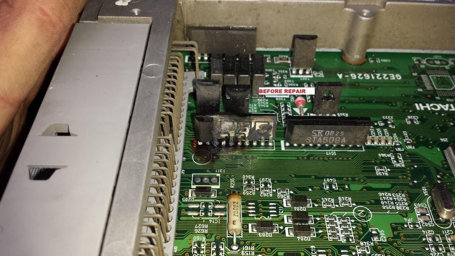
The above pictures are just examples. Not all damaged ECUs look like this. Sometimes, a burning smell is the only indication.
Appendix B – Notes re. Improved Fusing
Existing fusing:
Fuse #58 covers, via ECM relay pins (#6, #7), the following: MAIN, MAFS, POS, EGRC1, EGVC/V, AAC/C, TP/SW, IGN/SG (acronyms from the FSM). From the circuit diagram, this is only:
- IACV, EGR/C1, IGN/SG (Coils) – and nothing else; still, this is too much for a single fuse, so we must insert the fuse at F52 (the IACV connector)
Fuse #59 covers, via ECM Relay pins (#3, #5) the following: MAIN, MAFS, POS, EGRC1, EGVC/V, AAV/V, TP/SW, IGN/SG, EMNT, TPS, NONDTC, NATS. From the circuit diagram:
- ECM pins 110+112, CPS-POS, MAF, TPS, EMNT,
Solution requirements:
- Should be switched by ECU/other relays
- Avoid cutting the harness!
Possible implementations:
- Insert two fuses at IACV connector (F52). Insert them serially into IACV pins/leads #2 and #5. After splicing, bring the four “fusing” wires to some convenient place where the fuses would be placed. Use 3A fuses.
- New Power Circuit for IACV. Bring two new power lines to the IACV (use fuse adapters to create them). Fuse them either after, or before, the ECU Relay. The latter case will only work if the ECIU relay has two spare pin(s).
STA509A Datasheet:
http://www.datasheets360.com/part/detail/sta509a/-2407484356475109966/
Maximum current is 3A, max V is 47V
![]()
Comments are closed.