To regain use of the trip button after installing an aftermarket radio, you need to ground the thin brown/white wire on the small harness that plugged into the factory radio.


![]()
To regain use of the trip button after installing an aftermarket radio, you need to ground the thin brown/white wire on the small harness that plugged into the factory radio.


![]()
Community Member Credit: Dan Turk
I see people ask this a lot: Yes, you can direct-swap CarPlay head units in. I drive a ‘16 Bose and swapped with a wrecked ‘17 Bose. Match Bose or non-Bose and you should be good. The only “problem” is the 360° camera shows a silver car – the donor was silver and mine is red. Got the HU off car-part.com for $380 and sold my old one on eBay for $180. Not a bad $200 upgrade.


![]()
Member Credit: macdonjh
I’ll start with the reconnaissance I did in the front door. Several photos below:
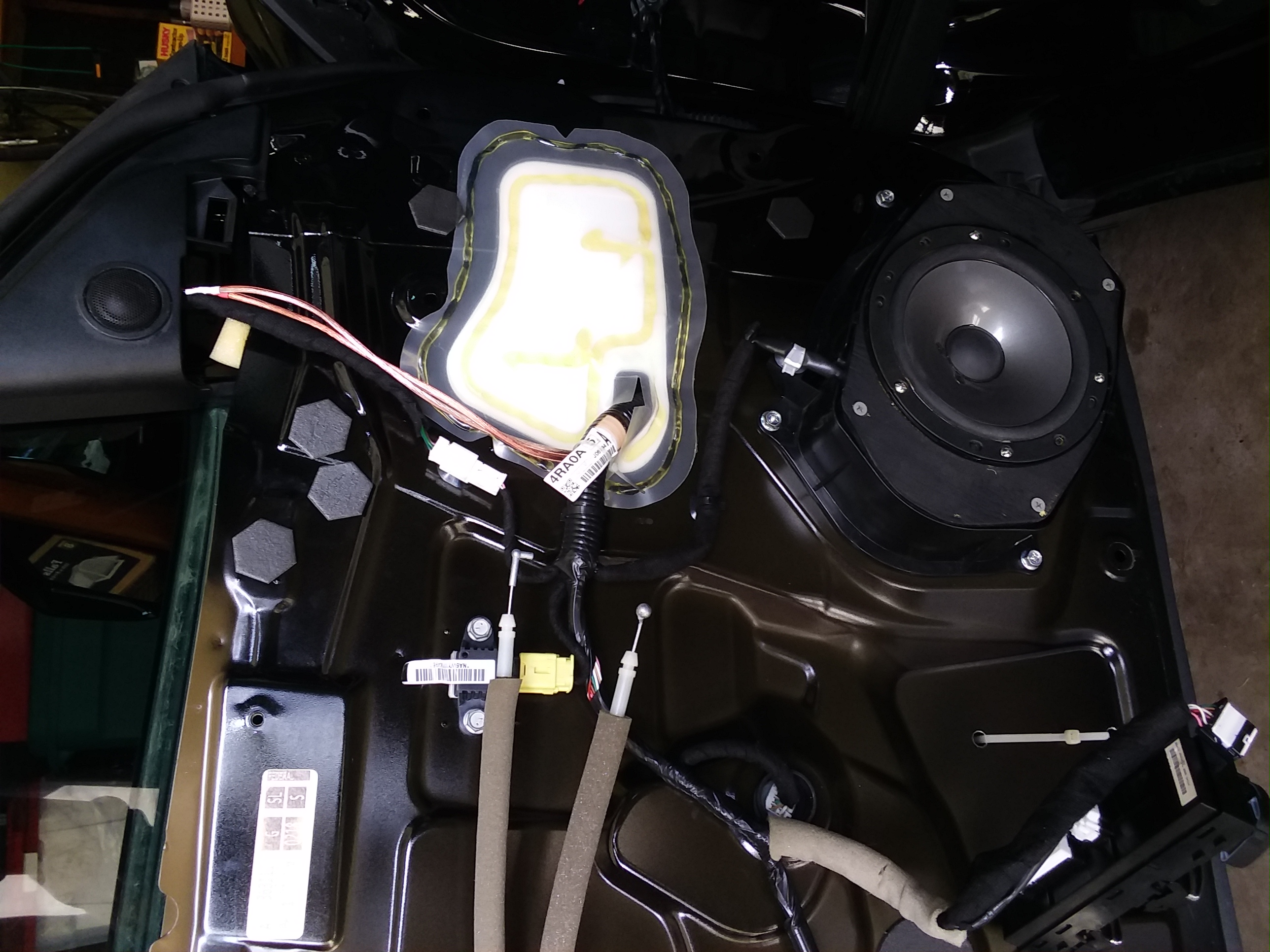
Front door: this is just a photo of the front door with the finisher removed.

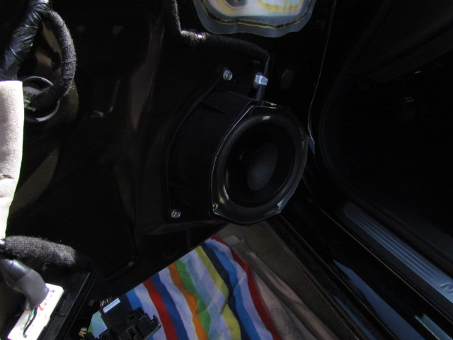
Front door speaker: a close-up shot of the 6″x9″ factory speaker in the front door. It has a plastic cone, foam surround and a paper whizzer cone. Another user asked for dimensions in a different thread, I’ll post those here: measuring from the back of the mounting flange the mounting height (how tall the speaker is measured from whatever you’ll bolt it to) is 3/8″, mounting depth is 3-1/8″, magnet diameter is 3-1/8″.
Front door speaker removed: gives you a look at the factory “enclosure” or “stand-off”. As Tommie70 said in his thread, there is a veritable cavern behind these door speakers. My installation will be like Tommie70’s in that I’m going to install plywood adapters into the factory “enclosures” and mount component mid-bass drivers there. Mounting depth with the “enclosure” installed is 7″. However, see below if you want to go a different route.
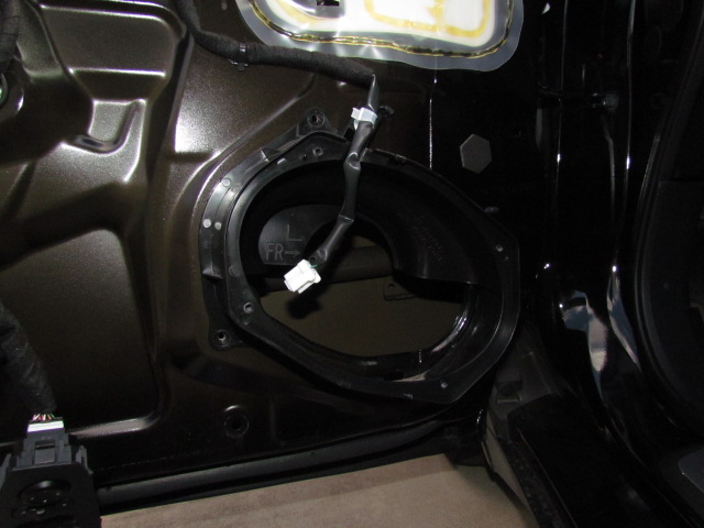
Front door speaker stand-off removed: Here’s what the door looks like without the factory “enclosure” or “stand-off”. The hole in the door is big enough (nominally 5-1/2″ x 8-3/8″) for you to reach at least half-way across the door for Dynamat installation. If you cut a plywood adapter to fit across this hole and match the factory bolt pattern (use the “enclosure” as a template) you could mount any coaxial speaker here you want. There is a structural bar across the door panel directly behind the speaker mount, but even with the bar mounting depth available is 4-3/4″. So without the “enclosure” you gain 2-1/4″ clearance between the speaker and door finisher for coaxial tweeters and such.

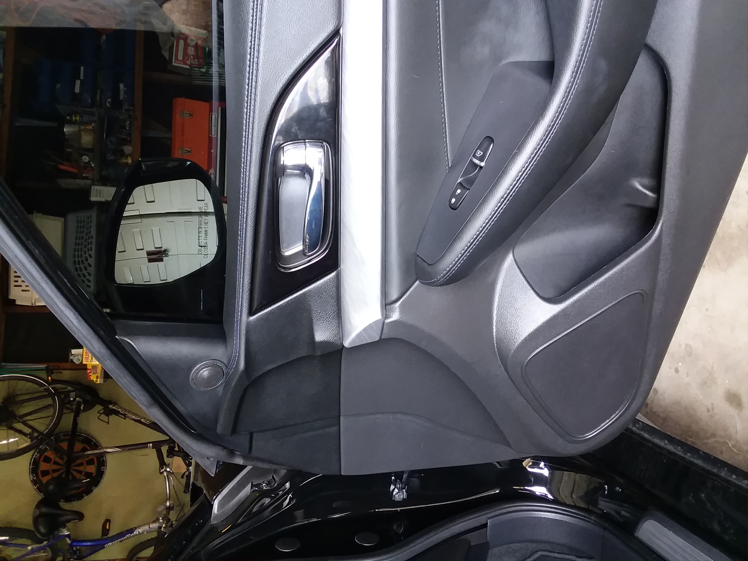
Mirror corner cover removed: this shows what’s behind that cover where Tommie70 mounted his front tweeters. None of the mirror mounting bolts or mirror control cable poses a problem, at least for the JL Audio 3/4″ tweeters I plan to install there.
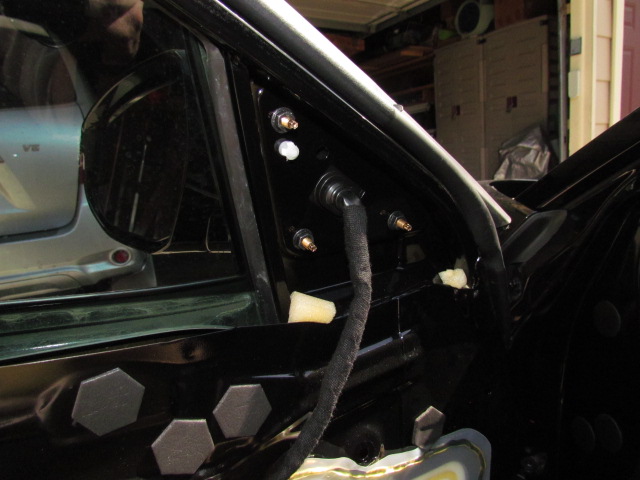
Mirror corner cover with tweet: this shows my 3/4″ tweeter resting inside the cover plate. I actually reinstalled the cover plate with the tweeter rolling around and didn’t have any trouble, so that’s where they’ll go after I’ve installed the new wires.
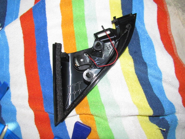
I forgot to run a fish through the factory boot between the frame and the door, but just feeling around it seems like there’s room enough to run a 16ga wire through the boot and avoid drilling new holes in the frame and door. I think I’d prefer to mount my cross-overs in the door anyway for shorter wire runs from the cross-over to the drivers. If I can’t fish a new wire through the factory boot I’ll consider pulling the factory speaker wires back through the boot to make room.
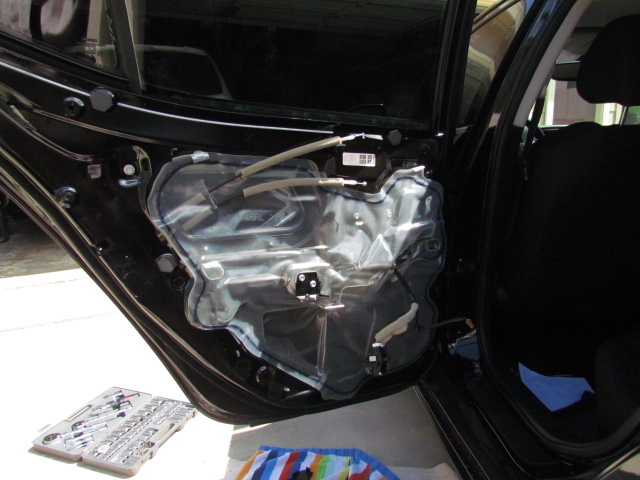
Here’s what I found when I took the rear door apart.
Rear door: A view of the rear door without the finisher installed.
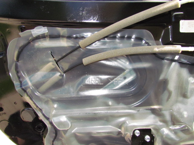
Rear door speaker location: a close-up photo of the inside of the rear door where the speaker would be. The speaker “sits” to the right of where that black cable (window switch) comes through the plastic. It’s hard to tell in this photo since I didn’t remove the plastic, but there is a metal panel directly behind the rear door speaker position, so after-market speaker options will be limited.

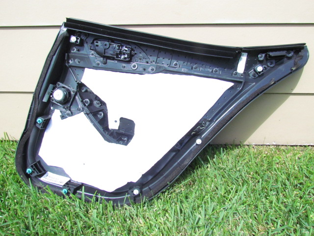
Rear door finisher: a photo of the inside of the rear door finisher. To fully remove the door finisher, remove the entire window switch assembly, not just the white part of the plug/connector. Then you can disconnect the speaker wire and the finisher will be free.
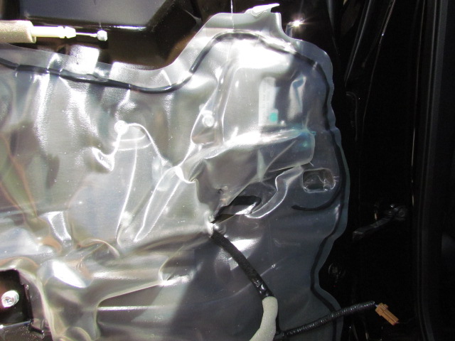
Rear door speaker: a close-up of the rear door speaker. The speaker itself measures 1/4″ from the back of the flange to the “face” of the speaker (mounting height), 1-3/8″ from the back of the flange to the back of the magnet (mounting depth) and the magnet is 2-3/8″ in diameter. I also measured the plastic mounting plate/ flange: 3-1/4″ square “outside-to-outside” with a square bolt pattern that measures either 2-5/8″ or 2-11/16″ on a side. Oh, yeah, the speaker itself is a paper cone, paper dust cap and foam surround.
Rear door opener cable hole: if you’re really skilled, it might be possible to use this hole in the door for a different speaker mounting location. I think it would require major modification to the door finisher, though. Just thought I’d post a photo.
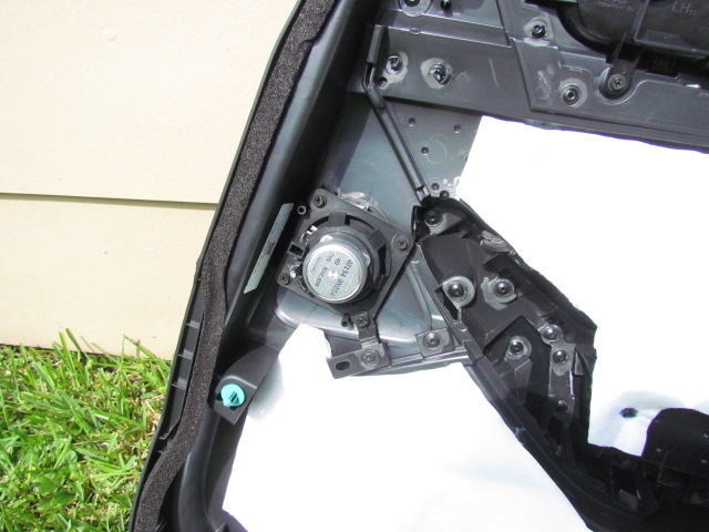
I’ve already stripped the screw holes that mount the rear door speaker, so please be careful. I am considering mounting rear tweeters in this location, rather than in the rear deck like Tommie70 did. If I do that, I’ll fill the screw holes with epoxy and then retap them when I mount the tweeters. I think tweeters flush-mounted to a 1/4″ plywood adapter plate would fit fine in this location.
I was not completely successful today: I got stymied trying to find a way through the fire wall. I couldn’t reach deep enough to get through either the hood release boot or the main harness boot. I didn’t feel comfortable drilling a new hole. I may pay an installer to finish this part of my install for me. Suggestions?
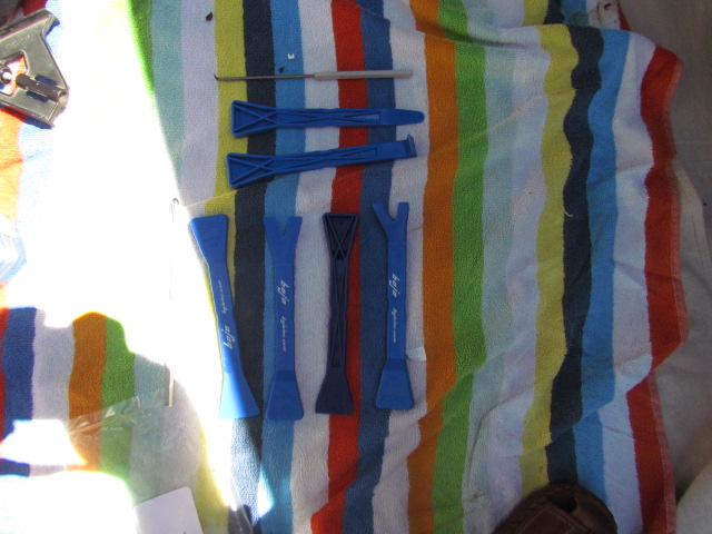
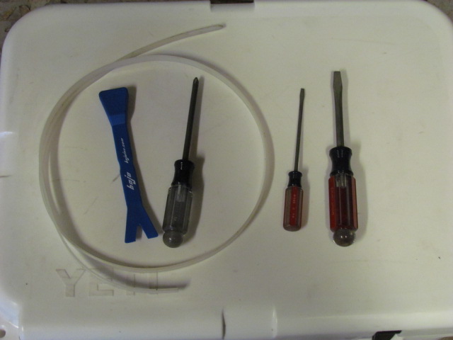
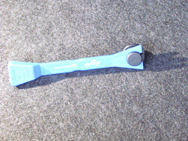
Here are the tools that I used for this part. Only a few needed.
I’ll make several other posts with details of the bits and pieces I took apart to route the wires.
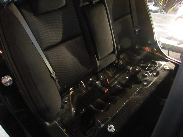
I started by taking out the rear seat, mostly. The seat cushion is as easy to remove as Tommie70 shows in his thread. The release handles are in the left and right corners and are easy to find by feeling under the cushion. Pull the release handle forward and pop the cushion up. Then pull it forward away from the seat belt clips. Be careful with the cushion: it’s only foam and upholstery, so it would be easy to damage/ crease.
The seat back proved too smart for me. For some reason only the passenger side seat back would fold down for me. I’ll have to talk with my dealer about that. I wasn’t able to remove the seat backs as you can see in the photos. The side bolters are held in place at the top by a couple of “pins”, just pull gently but firmly toward the front of the car and they will come loose.
Even with the seat back only partly out, I could follow the factory harness from the driver’s side sill into the trunk using the plastic wire fish I bought.
Sorry I don’t have more photos, most of them didn’t come out right.
I didn’t do things in this order, but for these posts, I’ll go from back to front.
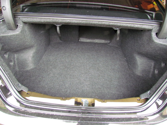
To get access to the trunk, start by taking out the cargo net and the trunk mat. Next, fold the carpet over so you can get access to the bottom edges of the left side finisher and the rear finisher.
Next, remove the rear finisher. First, take out the knobs that hold the cargo net in place. These are “super size” dual clips, so use a trim tool to release the top “button” the pull the knob out. There’s also a normal size dual clip which you can release with a screw driver. The rear finisher is held in place with four or five snap clips, pull gently but firmly straight up and it will come out.
The left side finisher is held in place by four or five dual clips and a bit of Velcro. One of the dual clips is in the “roof” of the trunk, so you have to look a bit. This opens up most of the left side of the trunk for wire pulling.
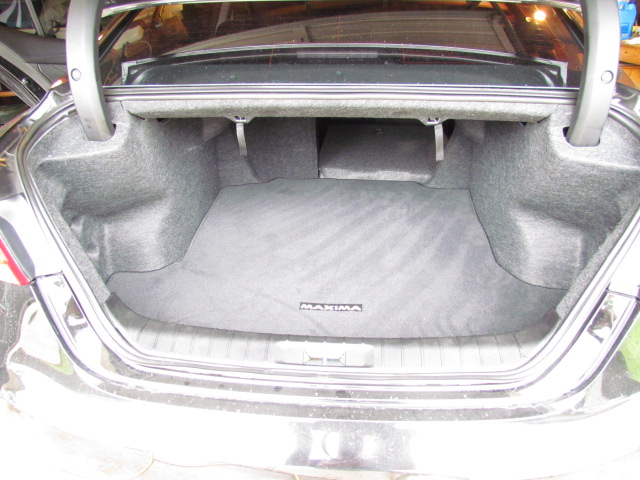
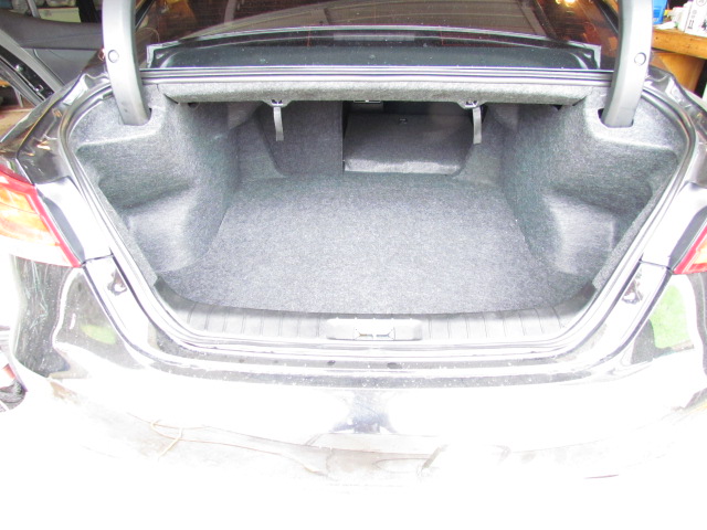
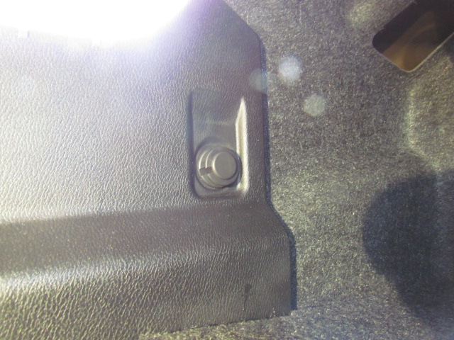
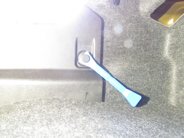
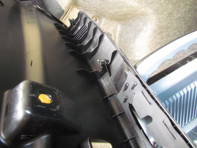
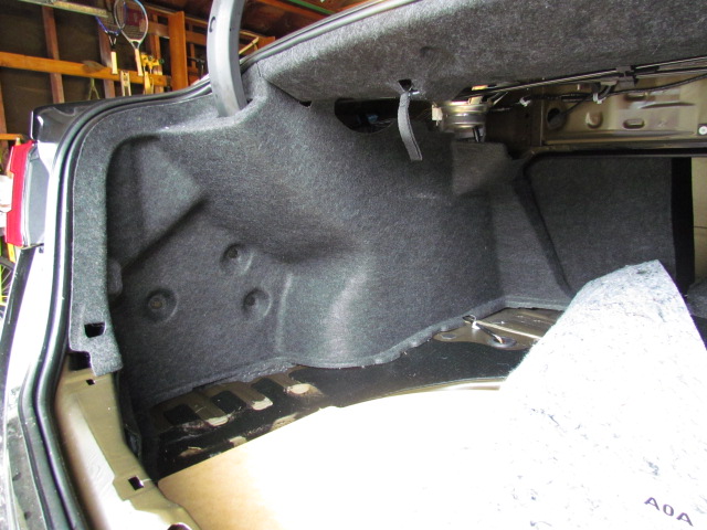
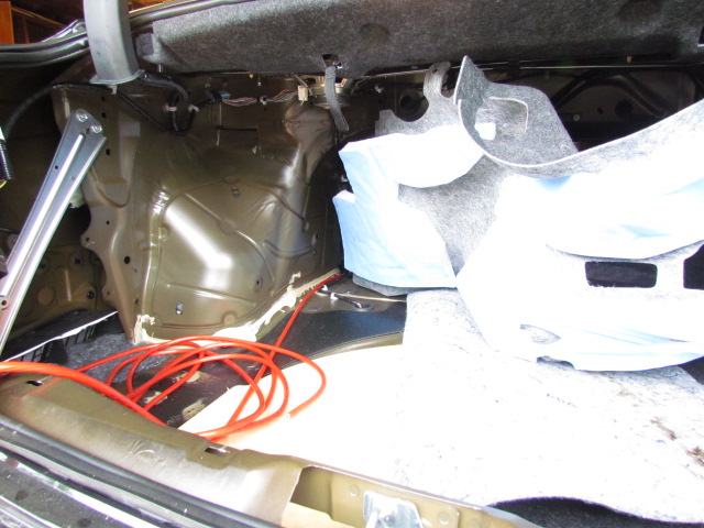
Once the rear seat cushion is out, the sill finishers can be removed by pulling gently but firmly straight up. I also released the finisher for the B-pillar, but didn’t remove it all the way. That at least gave me the ability to reach under that finisher for pulling the cables.
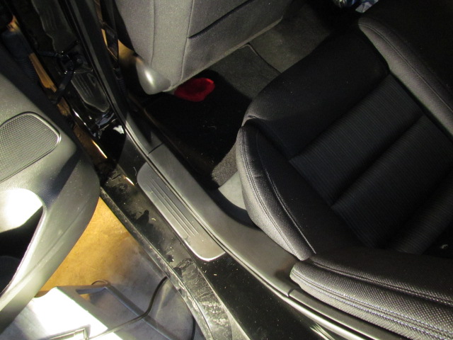
The kick panel finisher in the front of the car is a little harder to remove. It pulls straight away from the wall of the car, but the clips are tight. I didn’t post a photo of this, but I did pull the floor mat out and rolled the carpet out of the way looking for better access and visibility to the fire wall.
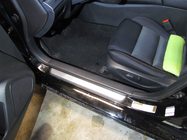
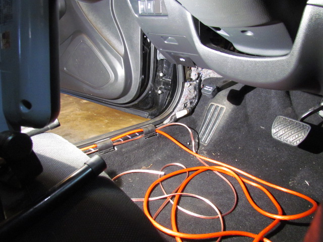
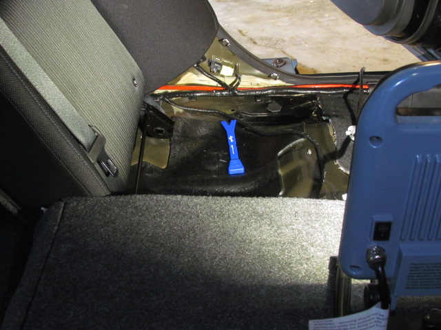
As you can see, there is plenty of room under the sill finishers for more wire. I am running 4 ga power and 16 ga speaker wire. At this time, the spare wire is coiled up and tucked up above the parking brake. I’m going to try to fish the speaker wire through the factory boot to the driver’s side door tomorrow. I may make another attempt to get through the fire wall, too.
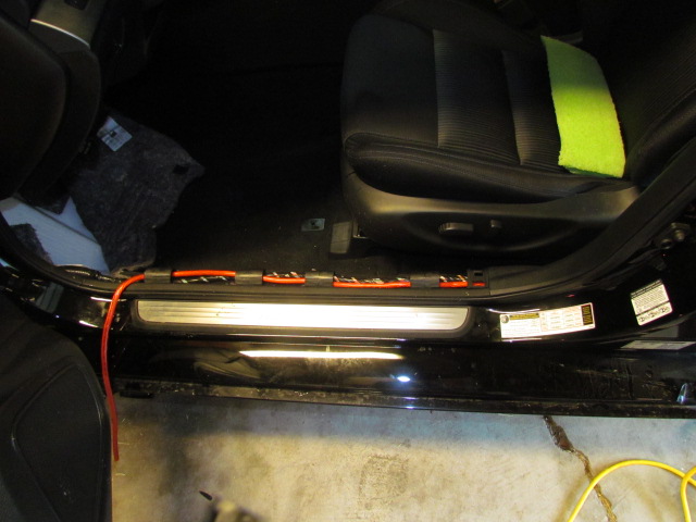
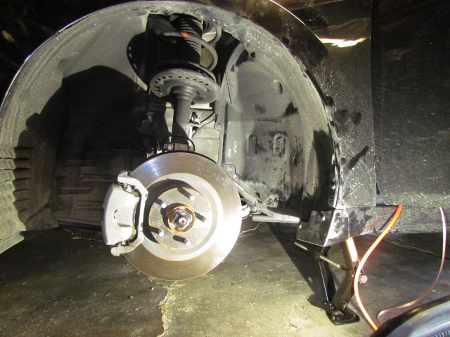
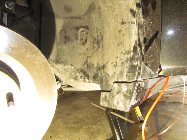
To try to get to the fire wall, I removed the tire and released about half of the wheel well liner. As I said, I didn’t have any luck finding a way through the fire wall today. Here are a few photos.
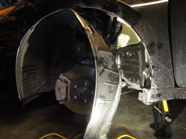
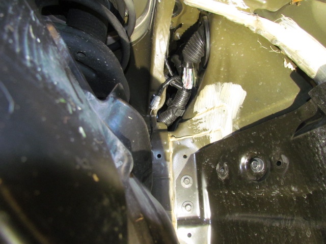
And a photo of the engine compartment showing the air filter removed. I think this will only be important once I find a way though the fire wall and need to use zip ties to run the power cable with the main wire harness.
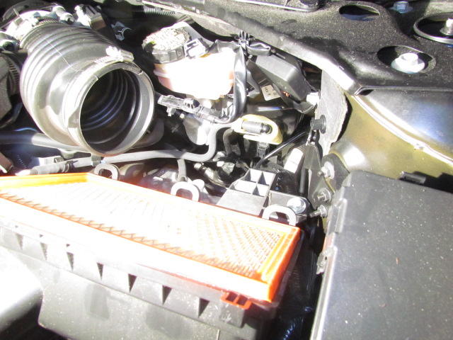
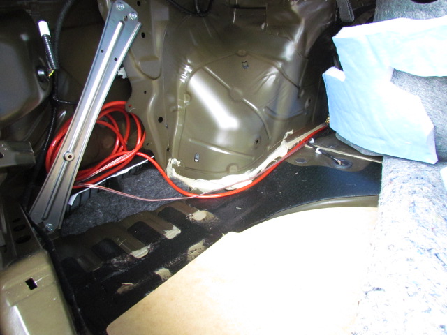
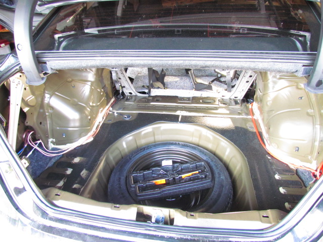
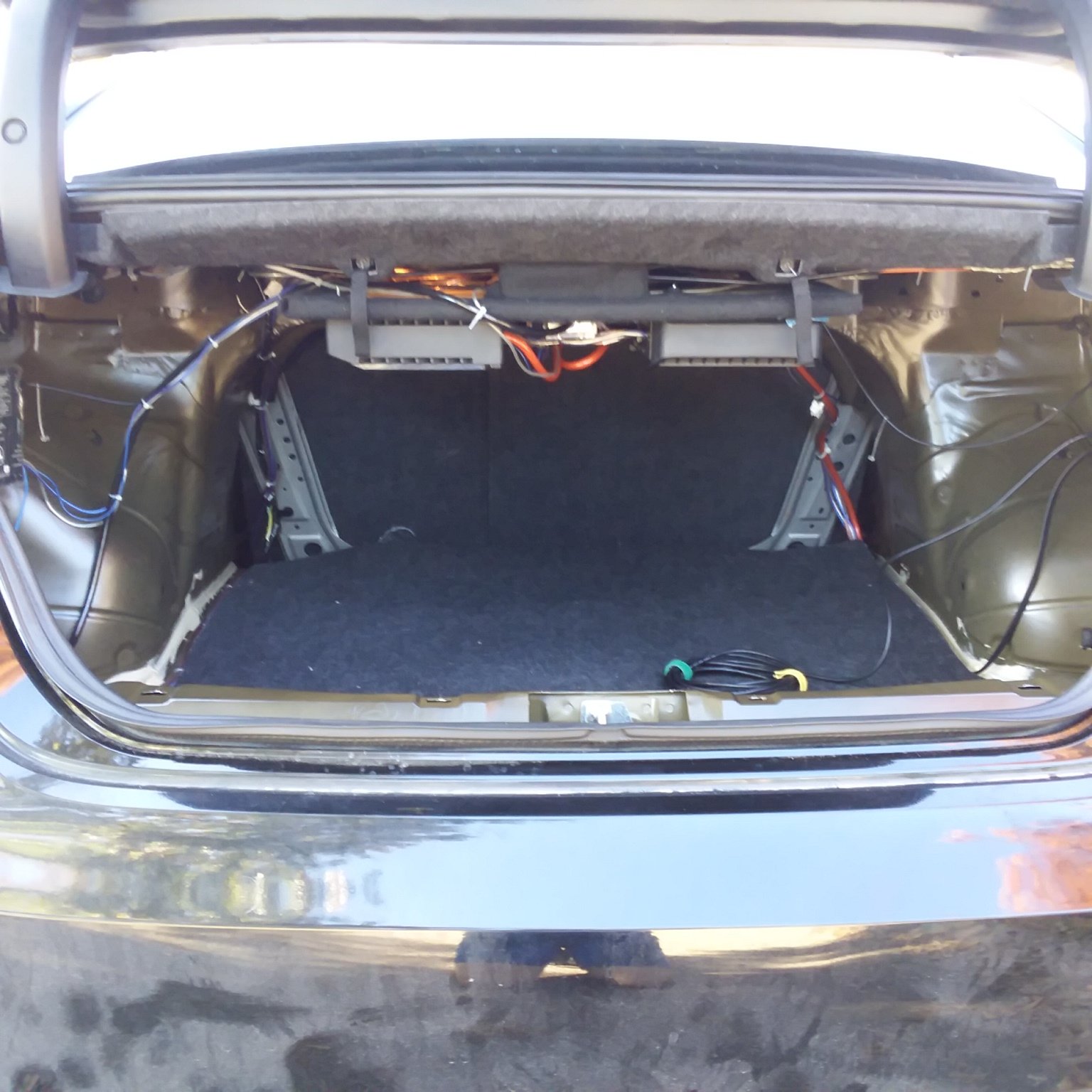
Here are some photos of the trunk showing where the cables come through, and where I’m hiding them for now.
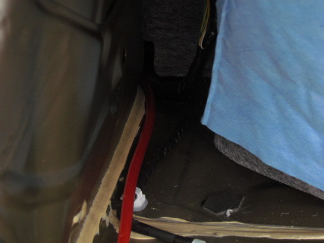
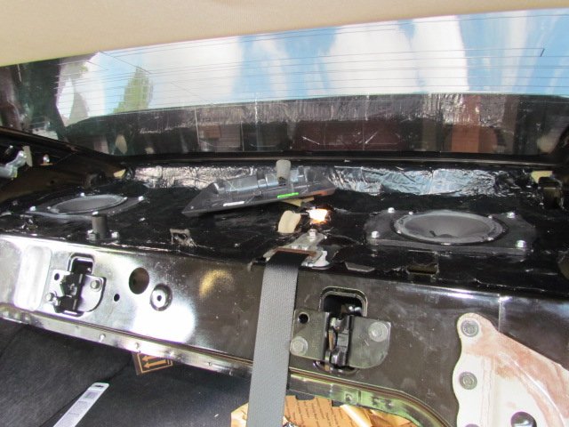
Now that I know how to get the back seat out, I lifted the rear deck finisher. Thank you YouTube. I’m sure I’m the only one that didn’t know about the black webbing tabs in the trunk that released the back seats to fold down; one for the driver’s side and one for the passenger’s side. To get the rear deck out:
The flange for the rear deck speakers is different than the flange for the front door speakers, so I’ll have to make two new adapters. I should have looked at Tommie70’s post a little closer.
You can see from the photos how much room you have to pull wires once the trunk and back seat are stripped. I’ve also verified, at least for myself, that there’s enough room behind the trunk side finishers for DSP units and amplifiers, in case you want everything hidden.
In the photos you can see the various wires routed into the trunk to their temporary hiding places. You’ll notice I repulled the wires. More about that next.
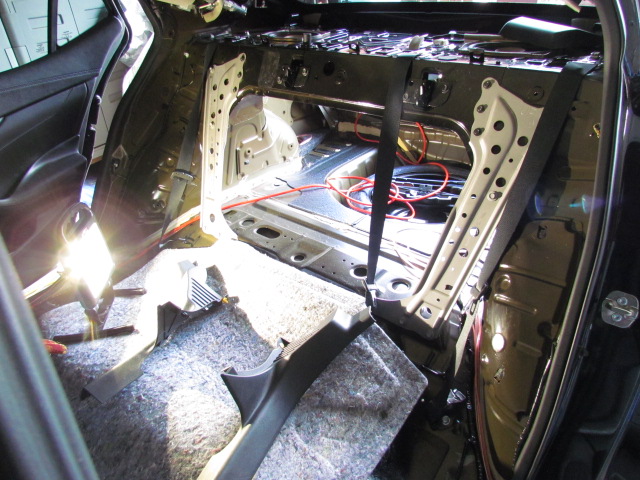
I decided to reroute the power cable through the cable chase along the passenger side under the sill trim pieces so I could take advantage of the unused fire wall penetration behind the glove box. The glove box is simple to remove: eight screws and pull gently but firmly straight out. Be careful of the harness for the glove box light and the trunk release cancel switch.
The fire wall penetration is slightly above the glove box on the right side, behind the “wool” insulation. There’s a grommet there, sized perfectly for 4ga wire. I doubt there’s room in that hole for 1/0 cable plus a grommet to protect the cable.
I’ve posted the photos in this order:
I haven’t connected to the battery yet. I don’t want voltage on the cable until I have a place to connect the other end. No, my power cable is not hanging out from under the hood; it’s wrapped around the fuse box and zip tied in place.
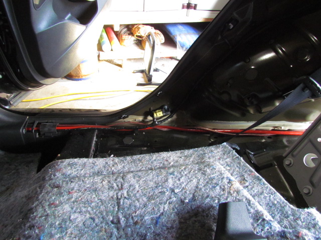
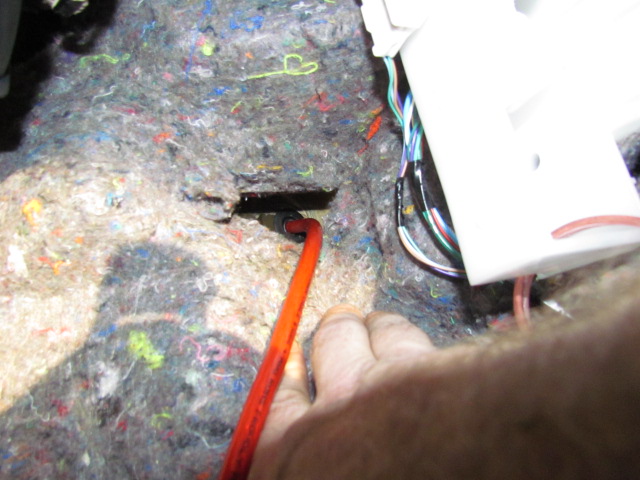
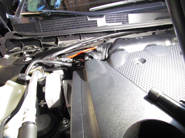

Since I moved the power cable to the passenger side, I also moved the new cables for the high level output from the factory head unit to the driver’s side. The route is the same as the speaker cable, so I didn’t post any more photos. Eventually, under the dash and to the back side of the head unit for connection.
Next step: amp boards: one for amplifiers and one for DSP units. The DSP board will be simple, the amp board more difficult.
OK, that SUCKED! The amp board kick my… I figured on five hours, it took nine. Holy cow. I won’t be doing that again.
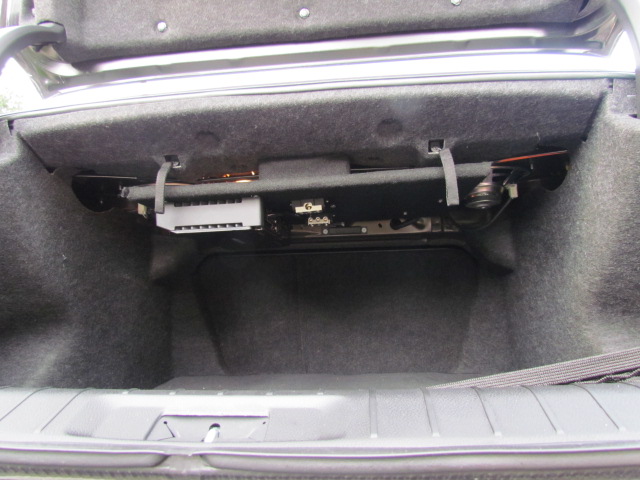
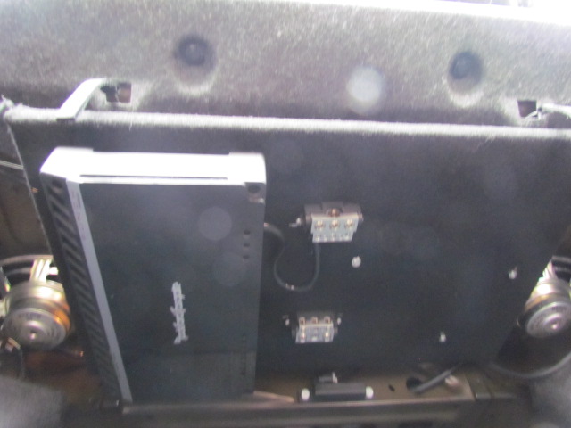
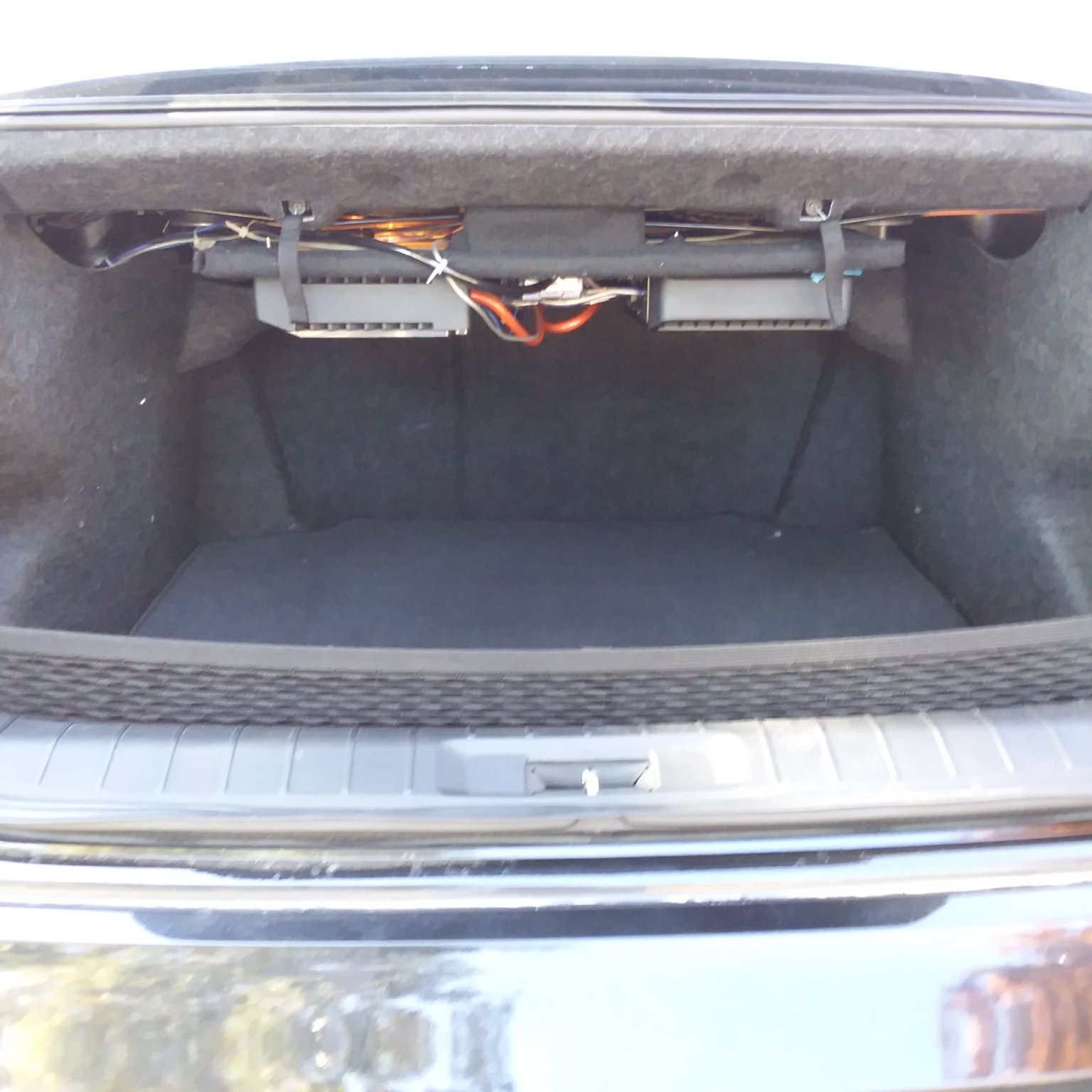
I simply had to have my amp under the rear deck and I figured a basic amp board wouldn’t be too complicated. The root cause of all the trouble is the number of protrusions on the underside of the rear deck. It isn’t flat. There are the trunk light (which I’ll eventually replace), the seat back release cables, the plastic studs that hold the rear deck finisher on, etc., etc. Complicating matters is the torsion spring for the trunk lid; it moves a lot as the trunk lid is opened and closed restricting where I could install bolts to hold the amp board up.
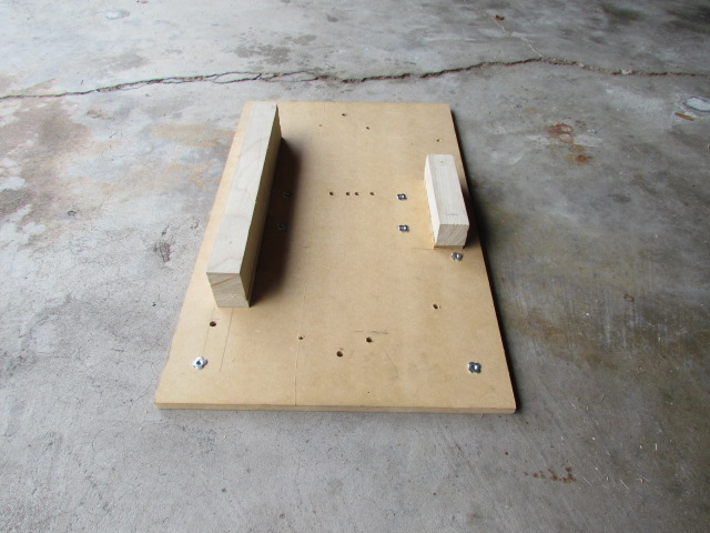
I had originally planned to suspend my amp board from long bolts, but changed plans and made some stand-offs so I could tighten the amp board against the underside of the rear deck.
I ended up using three existing holes in the rear deck and drilling two new holes. I wish I had figured out a way to have the mounting bolts for the amp board clear of the amp, that would have made things much easier to install. But two of the bolts are under the amp, so I had to install the board first, then the amp while lying on my back in the trunk.
My board is over-size because I’m trying to figure out a way to install a second amp to power woofers, so I am accommodating that at this time. I’d prefer for the woofers to be in the cabin rather than trunk-mounted, but we’ll see.
The moral of the story is perhaps Tommie70 had it right, install amplifiers against the rear fender wells.
I couldn’t have finished this part without help from my son, so, thanks to macdonsa.
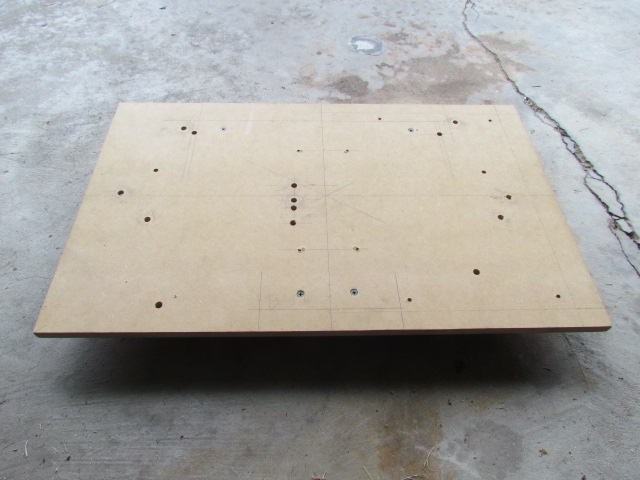
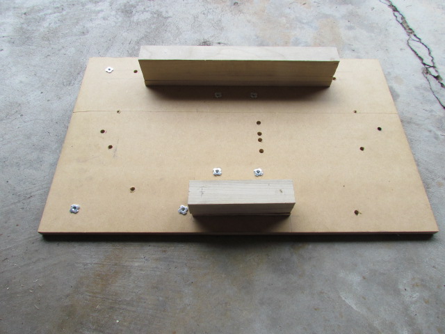
While I’m waiting for my DSP unit to be delivered, I took the head unit out and verified which wires need to be cut to tie in my new signal wires. Everything came out fairly easily.
The shift knob comes off easily. Follow the service manual recommendation and shift the car into neutral first to the shift lever slides in and out of the “leather” boot easily. The wire clip that holds the shift knob on comes off with a screw driver, then the knob slides off. There’s clear grease all over the shift lever.
The top of the console snaps out next. Start at the end closest to the back seat and work forward. There are a half dozen or so wiring harness connectors to disconnect to get the console out of your way.
You don’t have to pull the “leather” side panels, but I did. There’s an error in the service manual: according to the service manual each piece is held in by one screw plus the clips, but there are two or three screws, depending on which side you’re taking off.
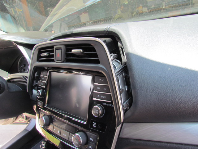
Next is the center A/C vents. The trim piece is shaped like an X-Box controller. Use a trim tool to pry the “horns” out first, then the vents will pop out. Careful, there’s a harness for the HAZARD light button.
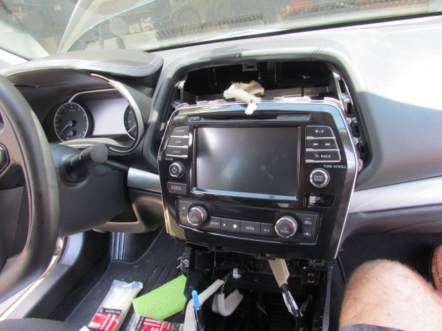
Now you can get to the four screws (two top and two bottom) holding the head unit in. Once the screws are removed I put my hand behind the unit and pulled it out. I wrapped it in a towel to keep the sharp brackets from scratching the rest of trim while I disconnected the various harnesses.
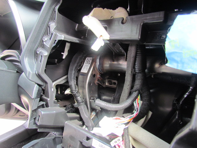
There’s a photo showing how much space there is behind the head unit. The biggest problem I’ll have routing wires behind the dash is finding something suitable to secure them to.
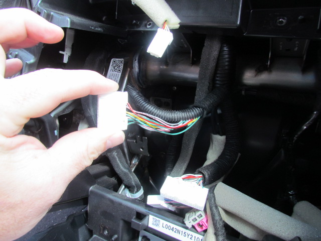
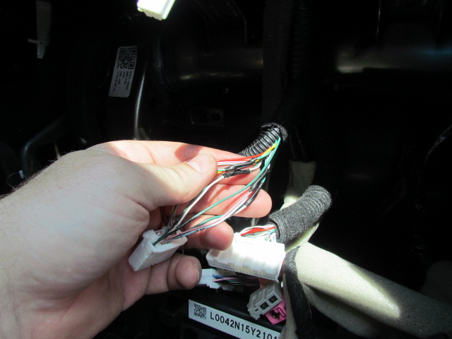
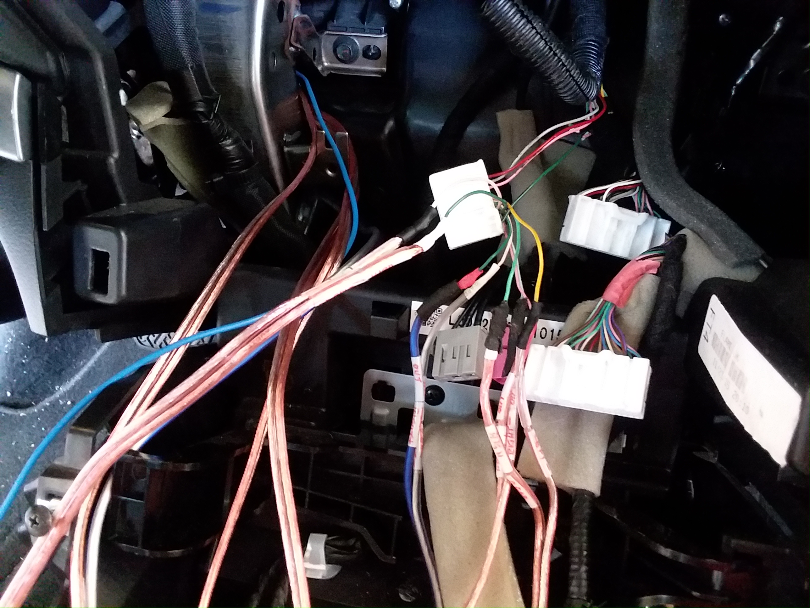
I’ve posted a couple of photos of the harness that has the outputs from the head unit to the speakers. I’ll tie in here for my new wires. The wiring is encased in a tar-coated felt tape and plastic loom. As you can see, I removed some of the felt tape to open the loom for access to the individual wires. I hope you can see in one of the photos that the wires for the speakers have black electrical tape on them. Your car might not, but mine did.
Here are a couple of photos of the inside of the center console. There is enough room in there, I think for DSP, mini-amps, radar detectors and laser detectors. The first photo is looking forward toward the dash, the second backward toward the back seat.
In the front half I think there’s room next to the shift lever assembly forward of where the cup holders are. That long strip with the “checker board” pattern is the air conditioning duct for the back seats. Between the gear shift lever assembly and the big well under the center arm rest is a pretty big cavern that could house electronics.
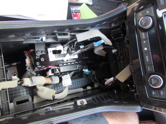
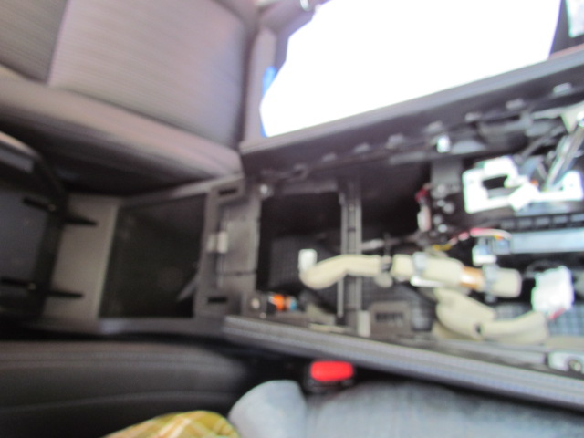
I found some errors in the Factory Service Manual:
Section IP-20: The figure for the Center Console Finisher (LH) and (RH) show one screw and five clips holding each finisher in. There are two screws for the LH and three screws for the RH finisher.
Section AV-183: The diagram shows the A/C switch assembly located above the A/V control unit (the factory head unit), but in my 2016, the A/C switch unit is below the head unit. It also comes out with the head unit, no need to remove it separately.
Section AV-44: The “physical values” table does not include connections 13-18. If you skip forward to page AV-62 you can see the pin-out for connector M-160, which has the output connections for the head unit. 2&3 are the front left speakers, 4&5 are rear left speakers, 11&12 are front right speakers, 13&14 are right rear speakers.
I’ve rung out pairs 11/12 and 13/14 and confirmed those. I’ll ring out 2/3 and 4/5 before cutting them when it’s time to install speakers.
Oops, I was wrong when I posted there is plenty of room behind the trunk finishers. In the first photo, you’ll see the left side trunk finisher installed. The left side, with the plastic fasteners, installs directly against the inside of the body panel. No room back there. The right side of the finisher covers up the fender well. There seems to be plenty of room back there, but much of the volume is above the fender well and all curvy, not suitable for installing rectangle-shaped audio gear.
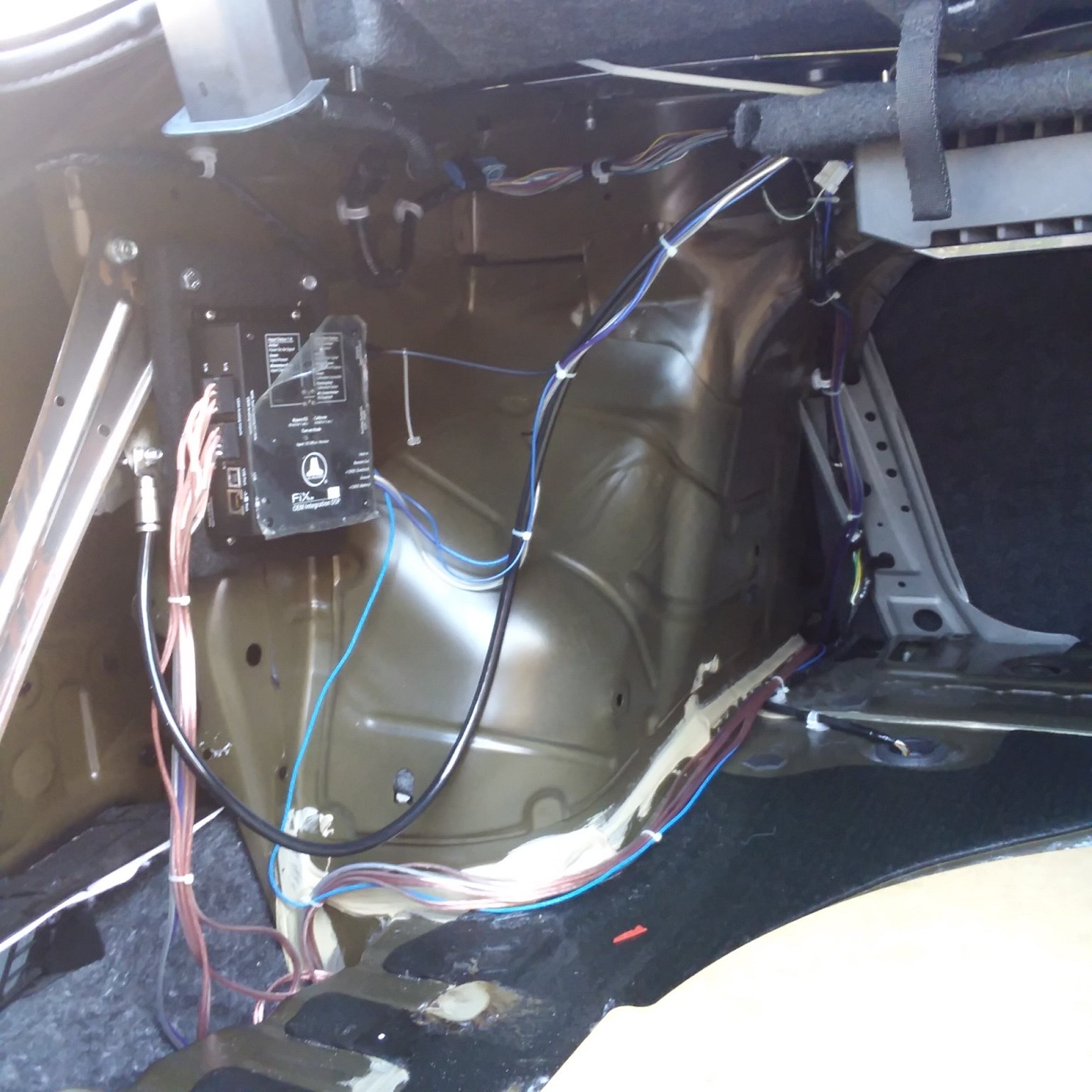
The second photo shows where I installed my FIX-82. I had hoped to get both the FIX-82 and TWK-D8 on the same side, but the TWK-D8 will have to be on the right side of the trunk. The area to the right of the FIX-82 is what I was referring to above, curvy and not suitable for installing audio gear. I ended up using one of the structural bolts that holds that silver diagonal brace in place, as one of the fasteners to hold the FIX82 in place. Those bolts are M8-1.25.
You may be able to see my chassis ground beneath and to the left of the board the FIX-82 is mounted on. It’s located in the triangular space between the right side of that diagonal brace and the FIX-82 board.
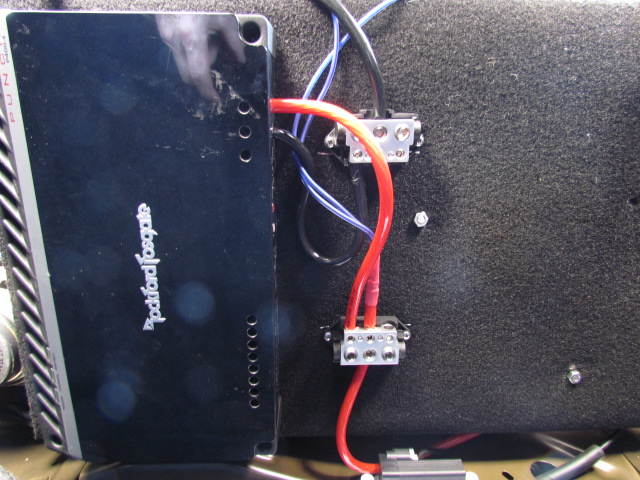
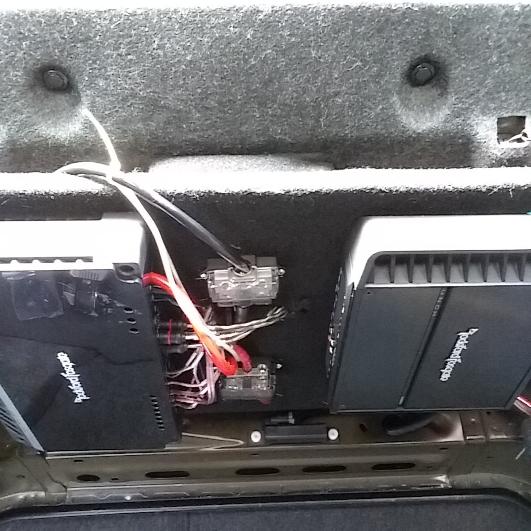
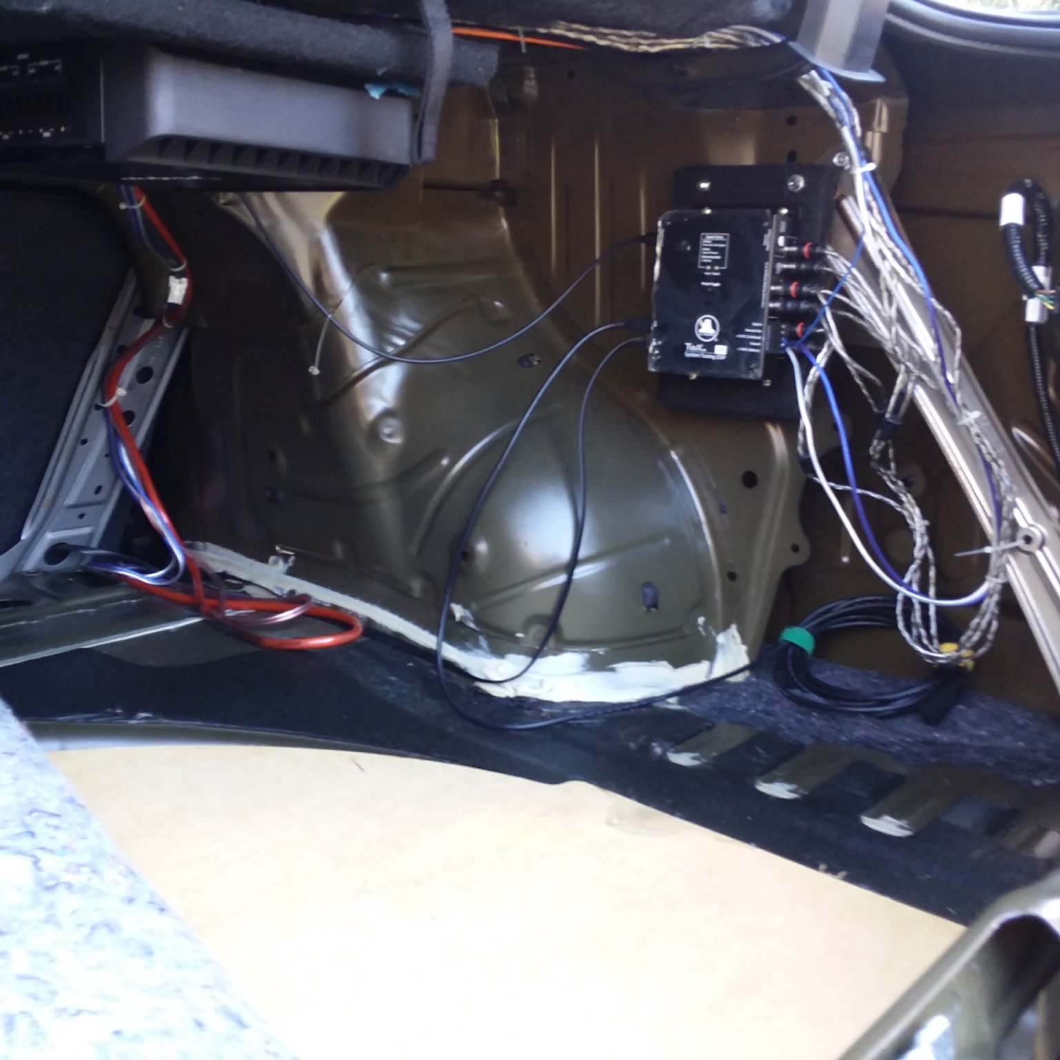
Finally, you can see the power and ground wiring in the third photo. Separate connections for two amps (another four channel amp is in the plan), I’ll power the FIX-82 and TWK-D8 from the same power connection on the distribution block.
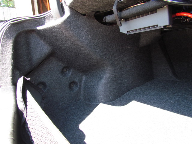
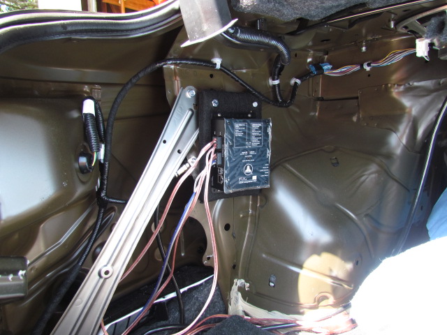
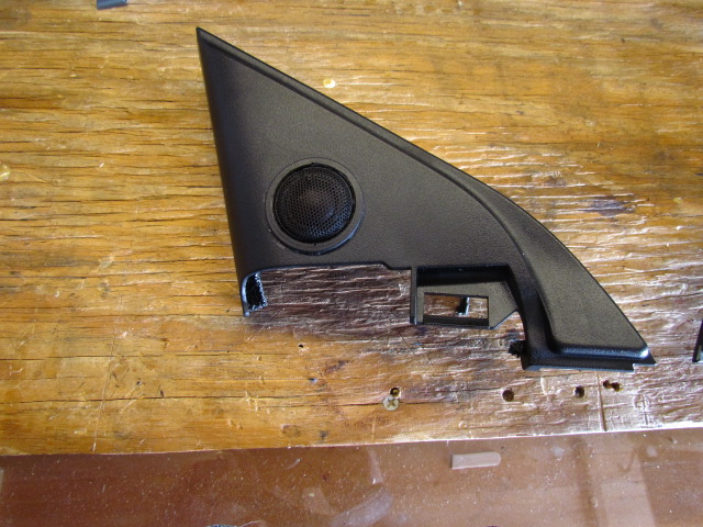
I was able to make some incremental progress today: I soldered the pig tails to my mid/woofers to get them ready to install. I also mounted my tweeters in the cover over the side-view mirror mounts.
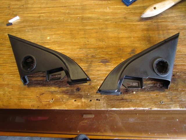
The first photo is the closest I have to a “before” picture. Sorry.
Then there’s a photo of both finishers with the manufacturer’s “basket” fitted. There may be room in these finishers for after market 1″ tweeters (I’ve read the factory Bose system has 1″ tweeters here), but I don’t know. It’s just about perfect for the 3/4″ tweeters I have. You may be able to see in the photo that I lined the basket with felt, which holds the tweeter in the basket quite well. Three dabs of Gorilla Glue hold the baskets in the finishers. Be careful with that stuff, it “foamed out” from behind the basket and made a mess on the front of the finisher. I found it in time and cleaned it up with mineral spirits.
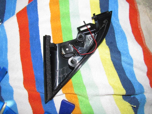
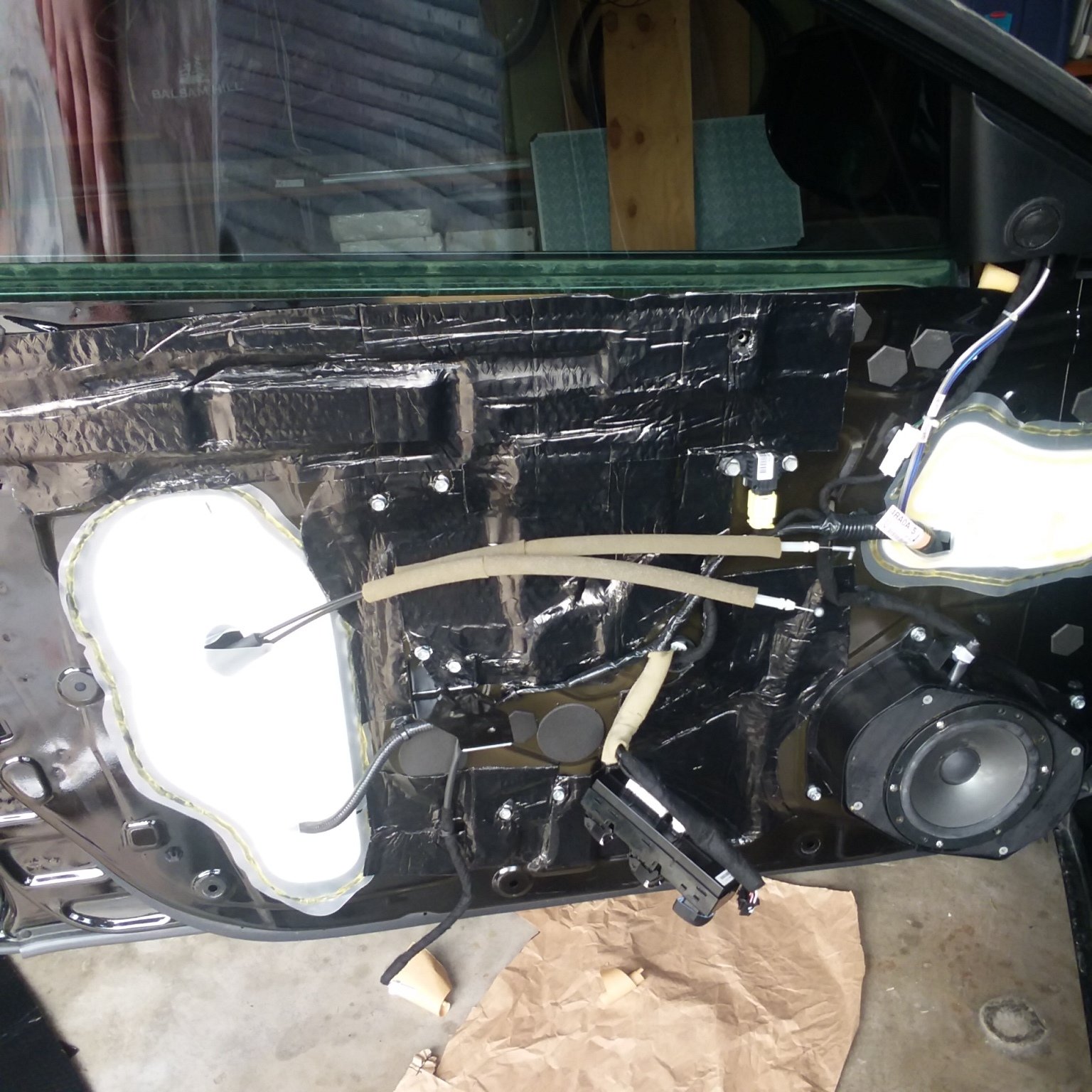
This morning I installed the speakers (mid/woofer and tweeter) in the front doors. Placing the crossover proved harder than I thought and I ended up putting it in a place I had intended not to put it: inside the door. I had originally planned to put the crossover between the door and the finisher, but I couldn’t find a spot that had room enough. Like the trunk finishers, the front door finishers proved tricky for me.
The first photo shows the driver’s door with the finisher off. At the bottom right you can see the 5-1/4″ mid/woofer I salvaged from my previous car. Left of that you can see the white zip-ties I used to secure the crossover inside the door. It does not interfere with the window rolling down in this spot. Above the mid/woofer you can see the wire from the tweeter snaking down to the hole in the plastic barrier to go inside the door to the crossover. For strain relief I used zip ties to secure the tweeter wiring to the factory harness it runs next to in the photo, and also to one of the fasteners inside the mirror finisher.
The second photo shows the passenger door reassembled.
Next step is to install the speakers on the rear deck and wire everything to the amp. I’ll also mount the JL Audio TWK-D8 and connect it. Last step for now is to cut into the factory harness at the head unit to tie everything in.
If you decide to remove the factory head unit, BE CAREFUL! There are two identical connectors back there and if you don’t put them back correctly, you’ll short out a bunch of stuff, blow a bunch of fuses and probably have to take your car to the shop for everything to get reset to factory defaults.
My car is back from the shop with all the blown fuses replaced and all internal computers reset. On the way home, it sounded like only the rear deck speakers (6-1/2″) were working, and full range at that. Still sounded better than the full basic factory system, if a little bass shy.
After dinner I confirmed that all the electronics were powered and ready. I set the “turn on mode” of my FIX-82 to “switched”, then performed the calibration. That was successful. Then I connected my laptop to my TwK-D8 and downloaded the set-up I had made. It still sounded like only the rear deck speakers were working, full range. I couldn’t hear any sound from the front speakers, but when I held my hand in front of the mid-woofers, I could feel them working. I’d connected the outputs of the TwK-D8 to the amp backward. After switching the RCAs everything was right with the world.
So now it’s time to sit back and enjoy much improved sound and do some tweaking (input levels to the amp, equalizers, etc.).
Phase 2 more amp channels, Phase 3 replacing rear door speakers, Phase 4 either Dynamat or bigger rear deck speakers. But that has to wait for a few months.
Just because, I decided to install the DRC-200 that came with my TwK-D8. The DRC-200 (Digital Remote Control) is a three-function remote: volume, preset selector, user-defined function. The volume function bypasses whatever speed-sensitive tone controls are in the factory head unit keeping the volume adjustment linear. The preset selector allows you to select any of the six preset configurations (signal routing, crossovers, equalization, signal boost/cut, delay) that can be stored in the TwK. The user-defined function can be sub level, fade/ balance or a couple of other functions. Details at JL Audio’s website.
I ran the cable from the TwK-D8, behind the right rear fender well in the trunk, into the center console. Unfortunately, the “during” photos I took got deleted, so you’ll have to settle for my description. I ran the cable behind the right side trunk finisher, then under the trunk floor mats to the back seat. Once out from under the trunk floor mats, I went under the rear seat back and under the rear seat cushion. I then fished the cable under carpet to the back of the center console. The rear of the console simply pops off, exposing plenty of room to route the cable. Then I fished the cable through the console, under the bin in the back of the console.
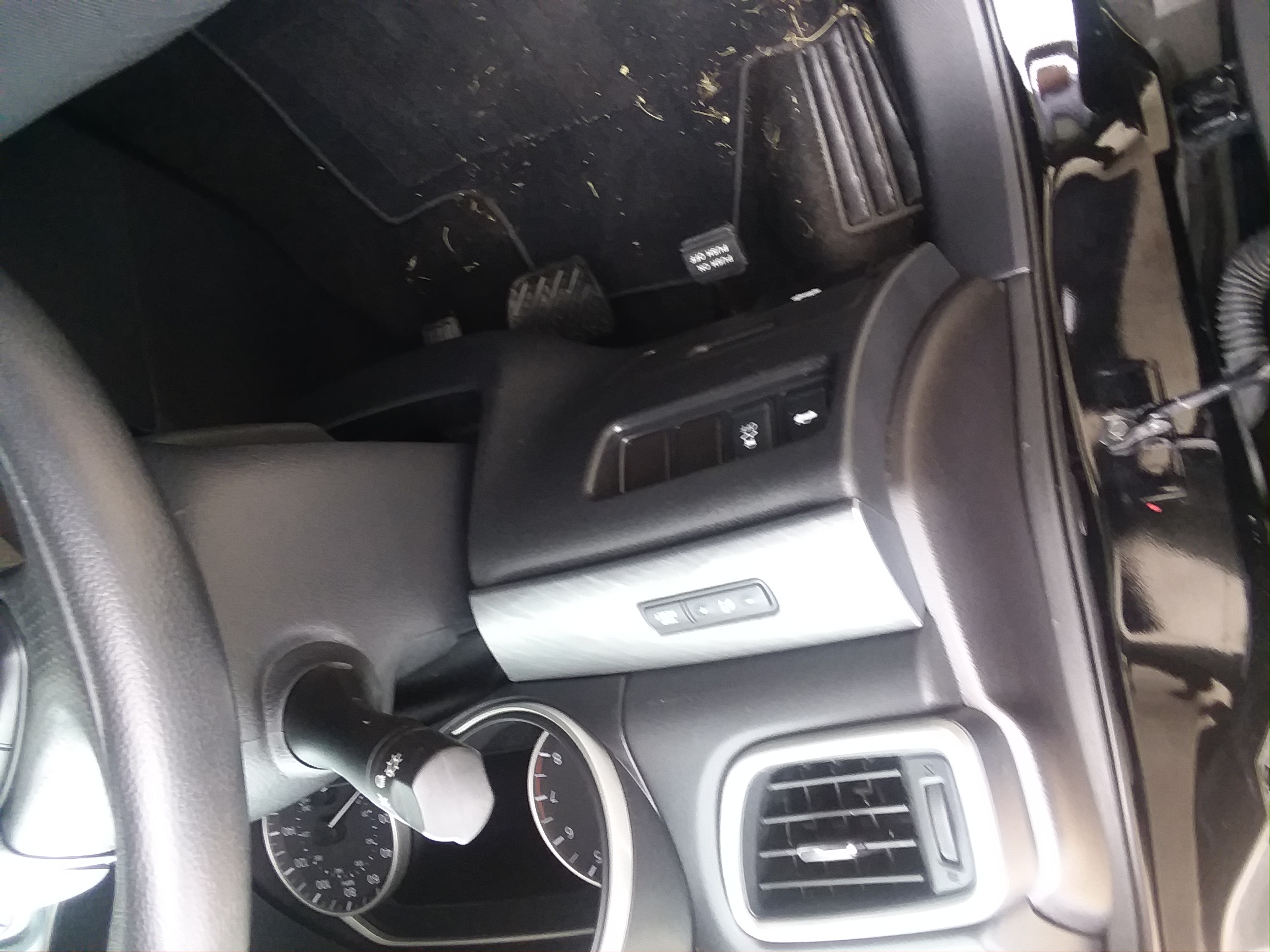
Now you can see in the photos I do have where I installed my DRC-200: behind the cup holder and in front of the console bin. Actually, the first photo I posted shows where I wanted to mount the DRC-200 at first, next to the trunk release button, with the indicator light in the silvery tri piece next to the trip odometer reset button just above. However, I realized what that would mean for a left-handed driver like me: lots of time taking my hand off the wheel to adjust volume.
The other pictures posted show where I did mount the control and LED. I really wanted it 4″ forward (that’s where my hand naturally lays), but that’s where the cup holder is, so there you go.
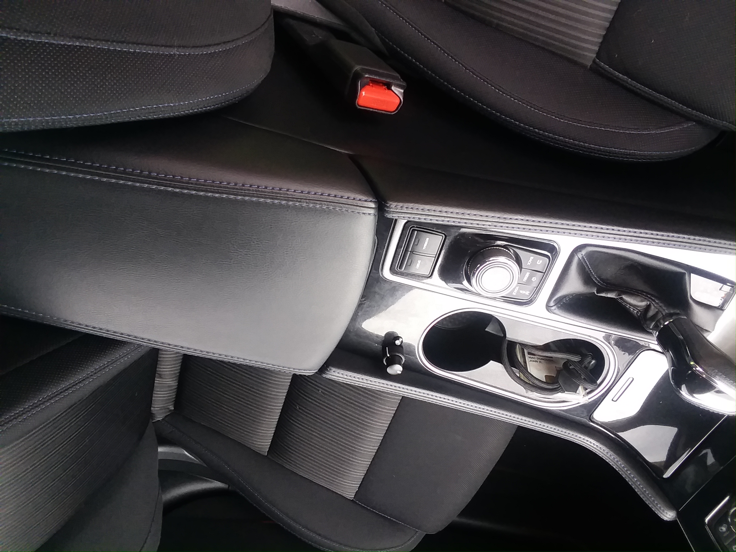
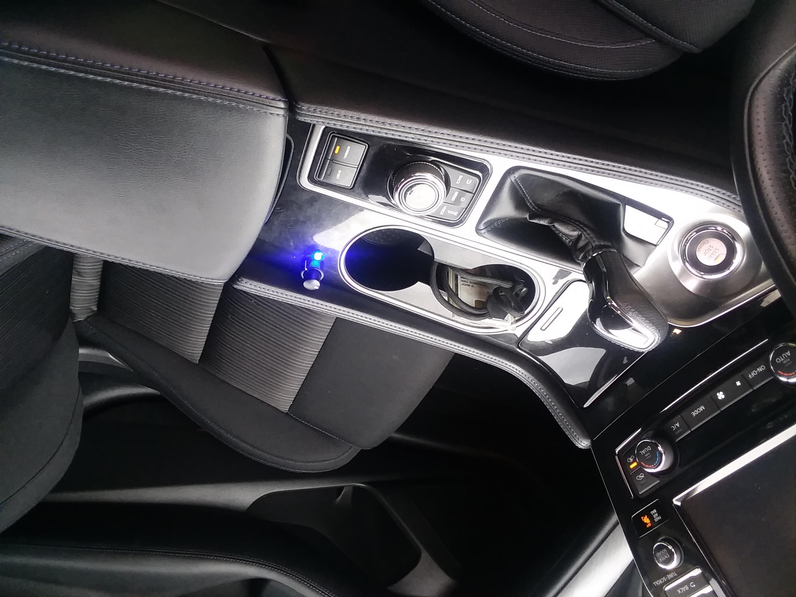
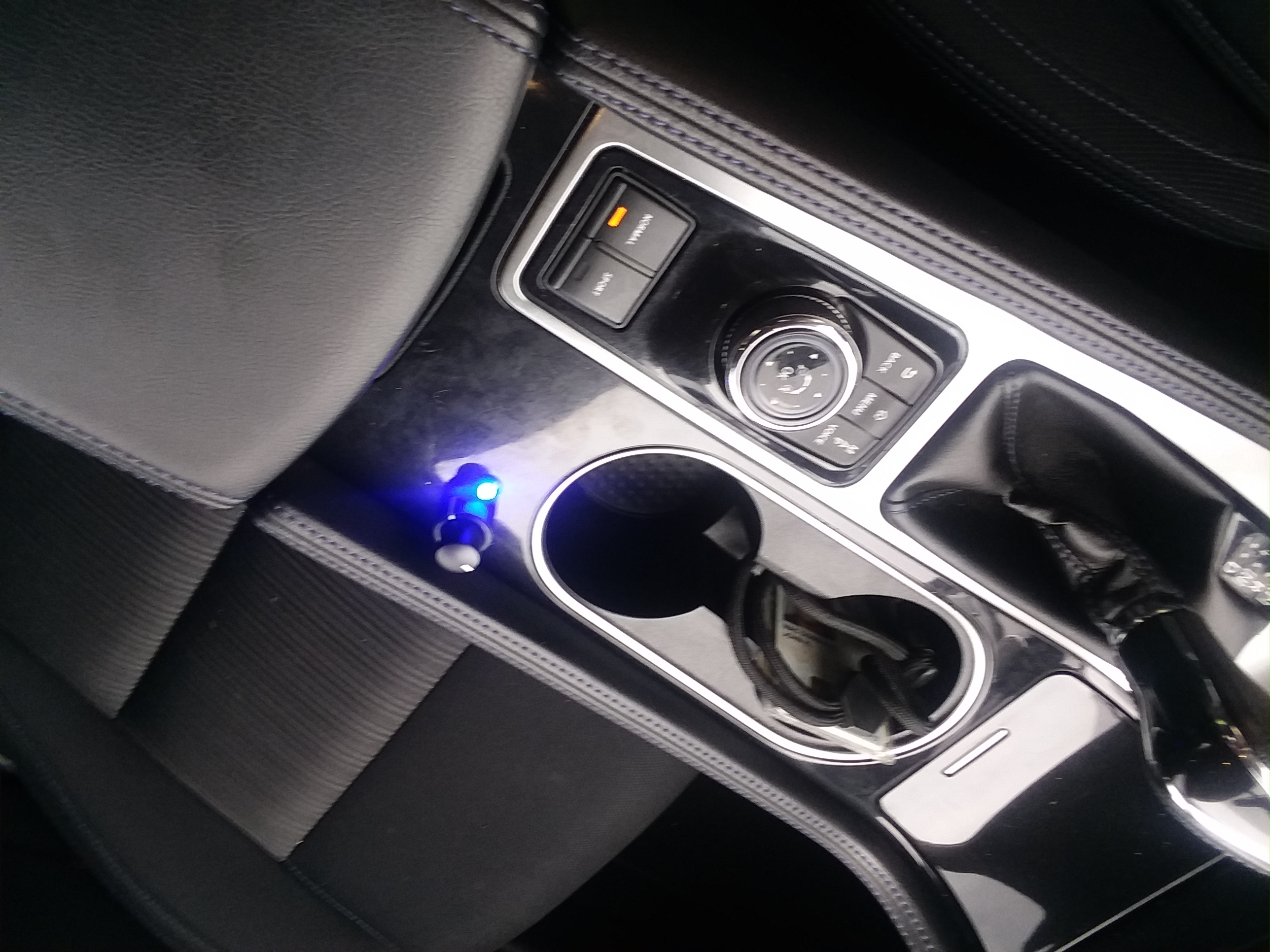
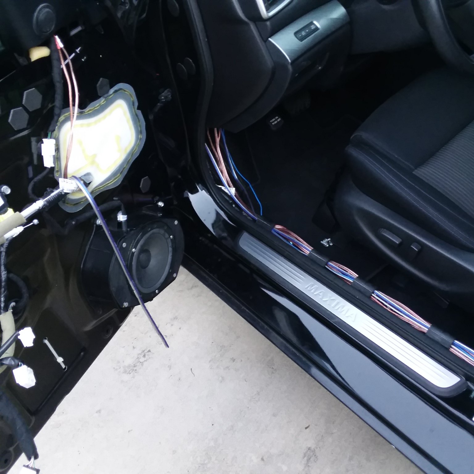 That dangling wire is the new wire for the tweeter.
![]()
Credit: the12volt
| Constant 12V+ | White/Red or White/Purple | Ignition Switch Harness |
| Starter | Black/Yellow or Black/White | Ignition Switch Harness |
| Ignition | Black/White or Black/Red | Ignition Switch Harness |
| Ignition 2 | Starter 2 Wire | Red/Yellow or Red Ignition Switch Harness |
| Accessory | Blue or White/Blue | Ignition Switch Harness |
| Tach | White/Green | ECM, Front of Center Console |
| Neutral Safety Wire | Green/Orange | Switch on Driver’s Side |
| Brake Switch | Red/Green | Brake Switch |
| Trunk Release | Purple/Yellow (-) | Driver’s Kick Panel |
| Trunk Pin | Purple/Yellow (-) | Driver’s Kick or BCM below Radio |
| Parking Lights | Red/Green (+) | Steering Column Harness |
| Head Lamp | Blue/Black R | And Gray/Yellow L at Steering Column |
| Hood Pin | Yellow/Black (-) | BCM below Radio |
| Factory Disarm | Green/Yellow (-) | Double Pulse Will Unlock Doors |
| Door Trigger | Red/White (-) | Low in Driver’s Kick Panel |
| Door Lock | Light Green/Red(-) | Driver’s Door |
| Door Unlock | Green/Yellow (-) | Double Pulse Unlock |
| Driver’s Lock | Brown/White | In Driver’s Door at Switch |
| Driver’s Unlock | Brown | In Driver’s Door at Switch |
| Passenger Unlock | Brown | In Driver’s Door at Switch |
| Horn Wire | Green/White (-) | Steering Column |
| Windows Up | LF=Blue/RedData Link Switch, Must go to each Switch in each Door | |
| Windows Down | LF=Blue/Black | |
![]()
Community Member Credit: Kenny
Hey guys, so for those of you like me that want the song title/cd title, etc to show on your display i finally found the solution! (if it hasn’t been found already). I’ve looked everywhere on this forum and didn’t seem to find the answer myself so i went ahead and experimented different ways of showing your CD info on the display when playing audio CD’s on your factory radio.
So now for the steps:

On the pictures below, You will see the boring (track #), then you will see your fun new display with the song name!
 It made a huge difference too me, now instead of seeing a boring display I can enjoy reading what im listening too, me personally i prefer it to say the track name, and maybe others will too….enjoy!
 PS. If you want your 04-06 to be like the 07-08 display that you can have it say anything you want, say I want my display to say “kaygmaxima”, all you have to do is name your playlist that your burning to the disc whatever you want and change your display setting with the right side knob and choose the option to show your “cd title” and when you play your CD your display will say whatever was desired.(i forgot to take pictures of that, but if really needed i will add to this thread when possible)
![]()
Community Member Credit: DAlastDON
When I bought my 07 maxima one of the things that sold me on the car was the intelligent key fob. Its nice to not have to dig in my pocket to get my keys out. Just walk up push the button on the door handle and im in. After talking to alot of alarm installers and a couple nissan dealerships they all told me that if an aftermarket alarm was installed i would lose the convience of the intelliegent key on the door locks. Also asked if it was possiable to add shock and tilt sensors to the factory alarm and was told that it could not be done.
This led me to google and i saw in alot of bmw, scion, toyota, etc.. forums of people adding sensors onto existing factory alarm triggers in the doors, hood, trunk pins. So i ordered three things, a DEI 507M(tilt sensor), DEI 504D(shock sensor) and DEI 528T(timer). Other items purchased from a local automotive store were, simple on/off switch, standard automotive relay, wire, and materials required to splice the wires together.
The relay is used to shut down the sensors when the key is turned on to avoid the info screen displaying that the trunk is open while driveing. The timer is used to temporaialy disable the sensors while exiting the car. Without the timer you would not be able to immedialy lock the doors and put the factory alarm in “pre-arm” due to the shock sensor sending a gound pulse to the trunk switch. It would cancle the “pre-arm” because it would sense the trunk was open and the alarm would never fully arm. If you wanted to wait about 10 seconds after the last door was shut everytime then the timer woudlnt be required.
Only four connections to the car are needed. One for constant 12v, Accesory 12v, ground, and the trunk switch.
First thing i did was draw a schematic of all the connections.

Next using a multimeter i found connections in the fuse box for 12v constant and 12v accessory. I used the fuel lid for 12v constant and cig lighter for 12v accessory. Then found a good ground next to the fuse panel. After finding the power connections the negative side of the battery is disconnected.


Next I decided where i wanted the sensors and timer/relay located. The sensors are located underneath the center console glued down using crazy glue gel and the timer/relay are located behind climate controls.


A simple push button switch was put inside center console storage space just in case it storms real bad and the wind/rain keep triggering the alarm.


Makeing the connection from trunk switch can be made from one of two places. Either at the BCM(pin#42) behind the fuse box or right at the trunk latch. Its a very small wire and i didnt have a small enough splice block to pierce the insulation at the BCM so i routed a wire from the switch i installed in the arm rest storage to the trunk latch. The wire is violet with a white stripe. I striped back enough wire to to stick into the connector then plug the connector back in. Make sure your wire will make contact inside the connector or nothing will work.


Routing the trigger wire from the switch in the armrest to the trunk is easy but going from the trunk to the trunk lid through the rubber hose and through the inside of the trunk lid is difficult. I pushed a stiff piece of wire inch by inch through the rubber hose. Put tape around the end of the wire so it doesnt poke through the hose as you push and carefully bend and guide it around the curve of the hose. Once through tape your wire comeing from the switch in the armrest to the wire you stuck through the rubber hose then carefully pull it back through. It will get stuck on the other wires several times. Just be patient. To get the trigger wire though the inside of the trunk lid it is even more difficult. I used a long piece of stiff wire and fished it from the latch to the rubber hose. It will take several attempts to get the wire though. Once through just tape the trigger wire on and pull it right through. It may have been easier if dynamat wasnt installed previously not only on the trunk side but also between the inner and outer skin of the trunk lid. Not pictured are all the cuts and scratches on my right hand.


The relay used is just a generic 5 pin relay found at any automotive parts store. I pulled my dash apart to see if it had a brand or part number on it and it had nothing. To the best of my knowledge any 5 pin relay with a normally open and normally closed contact will work. I got mine from autozone. I just told the guy at the counter that i needed a 5 pin relay. On the bottom of the relay the pins are numbered. Make sure the one you get has and “87” and “87a”. The letter after the “87” can be anything. On mine its “87q”.
I have zero problems. The intelikey works exactly as it did before.
The trigger outputs are connected to the trunk pin(switch). A picture is worth a 1000 words. Cant make this any clearer.

Be sure to turn the sensitivity all the way up on the shock sensor via the screw adjustment on the sensor. When i roughed the install in to test it and had everything just laying in the back floor board just a little peck on the window would activate the shock sensor. But after putting it under the center console i had to turn it all the way up and it takes a good thud on the window. The preset sensitivity of the tilt sensor is perfect, it triggers after the car has been jacked up a few inches at all four tires. We have had a couple of good thunderstorms with 50mph winds with no false alarms yet.
Picked this up at autozone where the fuses are. It allows you to tap into one fuse socket and fuse two items separately. Im going to add another to the fuel lid connection soon so i can fuse it separately as well. Didn’t feel like making another trip to autozone to pick up another at the time. Make sure its for the mini fuse and not the full size.

![]()
Original Music Credit: TrixXx (Brian B.)
I was finally able to get a hold of Brian who made this song back in 2009 for the Maxus09 event. I couldn’t find it for years. But here it is. This deserved its own official post.
Thanks Again Brian.
![]()
Member Credit: 415Max96
So I installed Polk DB6500’s and DB650’s (rear) today, managed to snap a few pics:
INSTALLING REARS
1. Start by taking off the doors.
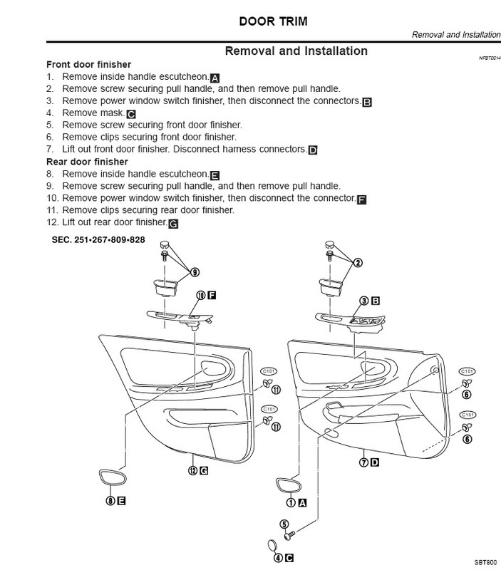

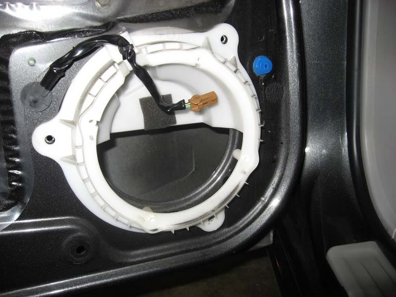
2. Rear bose speaker is a 5.25 attached to a protective plastic piece. unscrew speaker and disconnect

— you will have this left, now remove the white piece, its held by three screws
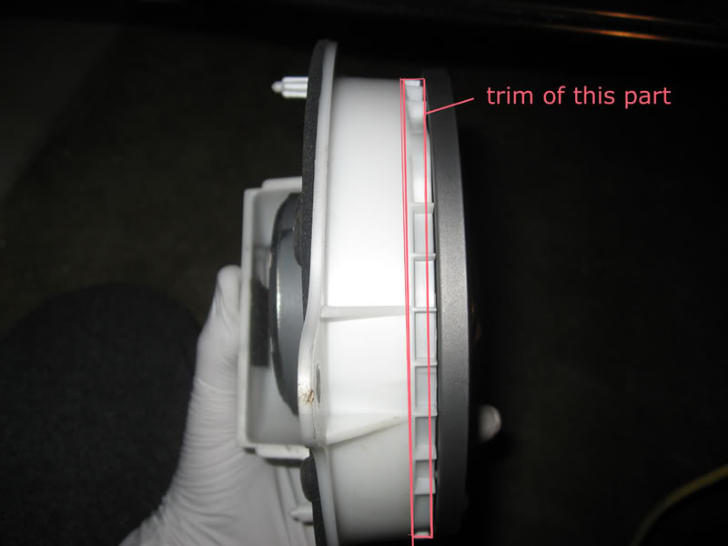
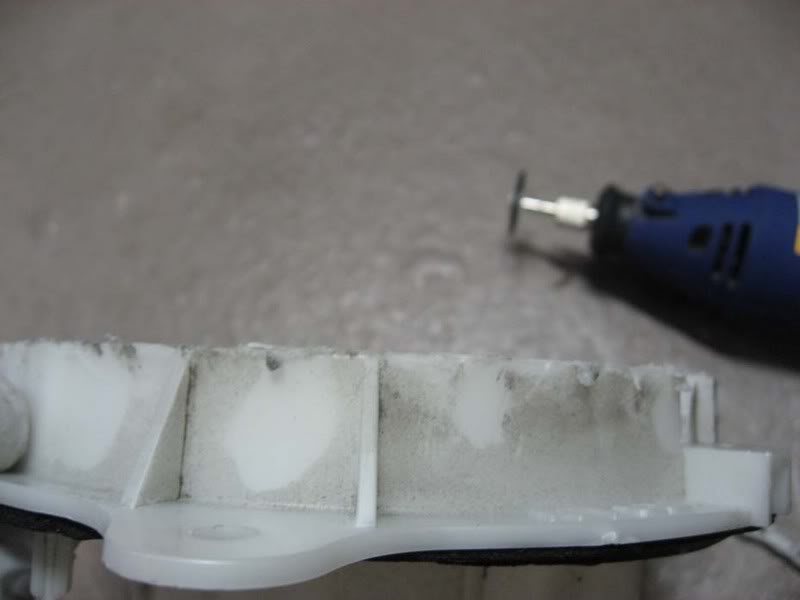
3. The new 6.5″ polk met some resitance from white piece, the trim on top did not alow the speaker to fully submerge so a trimming had to be made
—————->
4. Attach the new speaker, if it comes with the foam padding, place it between speaker and the white piece
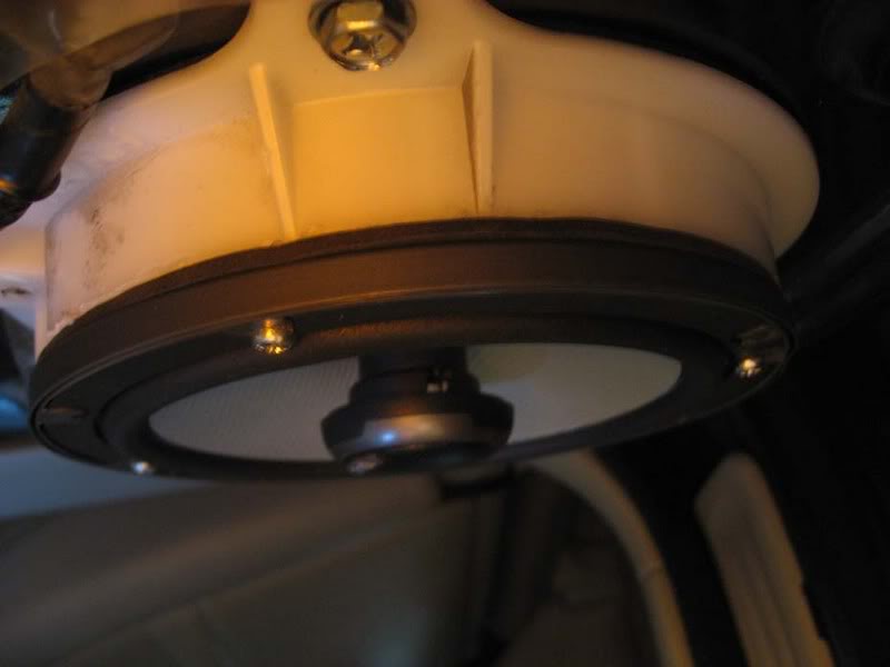
5. Easy as cake, make sure evrything works and remember to put all plugs back in their respective places, put door back on and your ready to get crackin with the fronts 
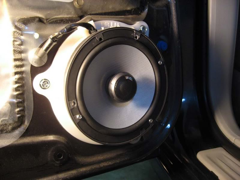
THE FRONTS
1. Refer to step 1 in rear doors and remove front door panel.
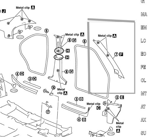
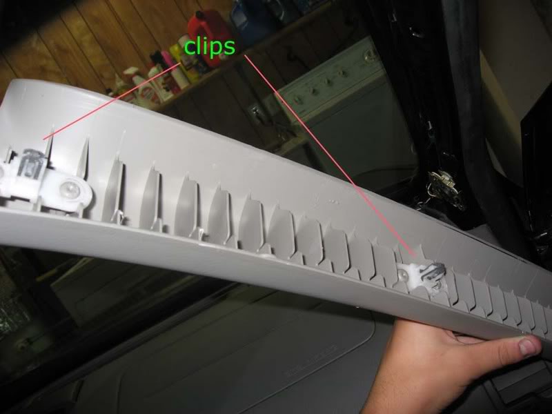
2. Remove the A-Pillar, its help by to clips
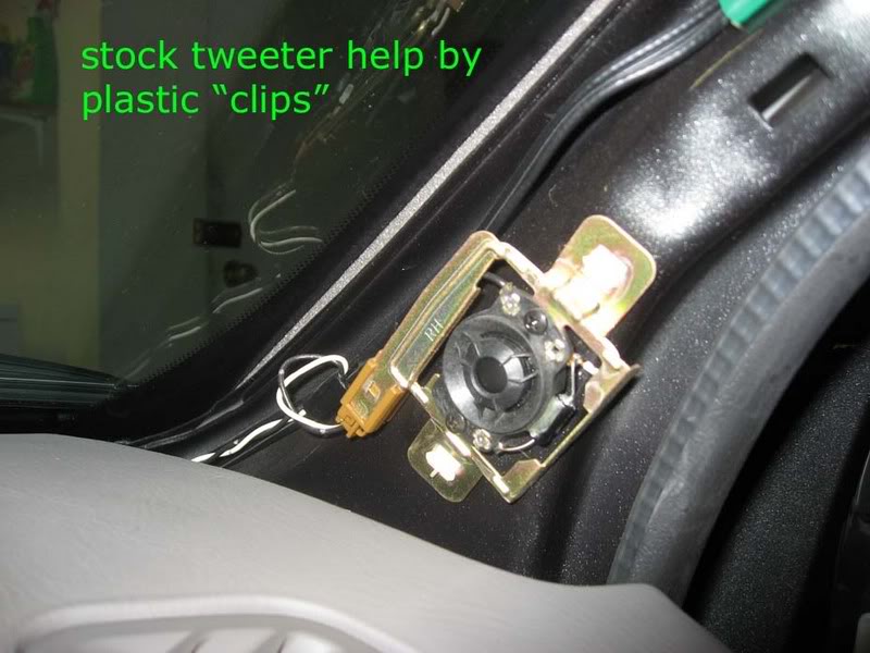
Here we see the pathetic stock tweeter…i had to put on my grandmothers glasses to see that it was a tweeter and not a glued on dime
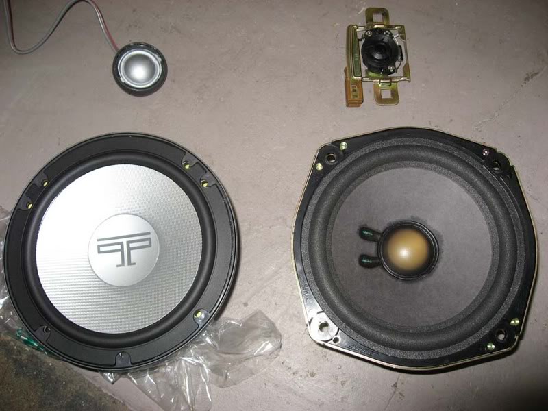
Comparrison of OLD and NEW Polks
and the Tweeters
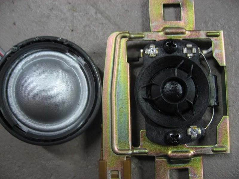
NOTE; be carefull not to damage the tweeter in removing the grill, i got into a liitle rush and ended up poking the tweeter, thank godness no performance damage
3. Installing new tweeters; since their is no way to use the stock mount for the new tweeter i had to improvise with some industrial velcro. Yes, its ghetto; how well it will hold up i will have to wait and see. After install i took it out for a drive and did not notice any rattles coming from either side.
The cable I ran the new cable throught the weather stripping. peel it back, insert new wire, put it back.
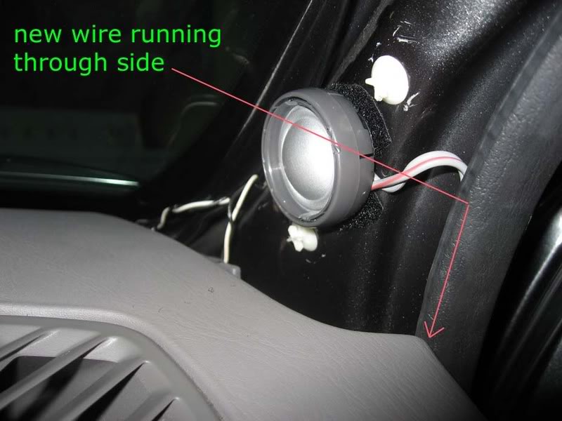
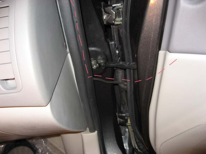
I tried to see if i could run the wire through the rubber protector that runs all the stock wire from cabin to door, however i found that their is not 1 cm of space for the new wire. I ended up using rubber heat shrink to cover the exposed wire between the weather stripping and the part were it enters the door
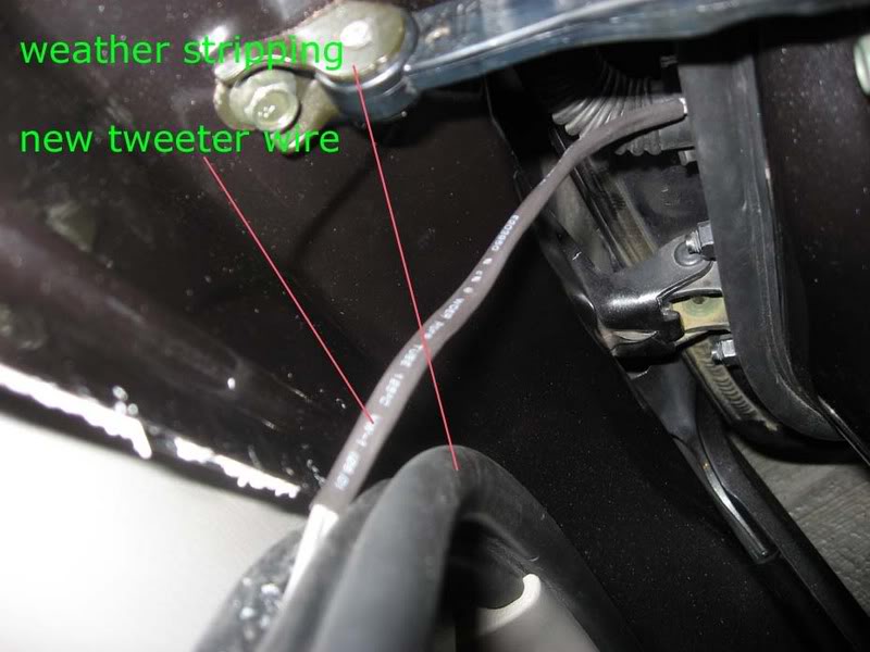
4. You CAN however, feed the tweeter wire through the door side of the rubber protector and fish it out of the other side
NOTE: carefull not to allow the wire to interfere with teh operartion of the window rail.
I forgot to take some pics but you can get the idea of were the wire should run to. Also note the location of the Crossover. It is securely ziptied and did nt seem to make any noise during install or during the test drive, hopefully it will hold up and wont need to be relocated. Their were no fitment problems during re-installation of the door panel
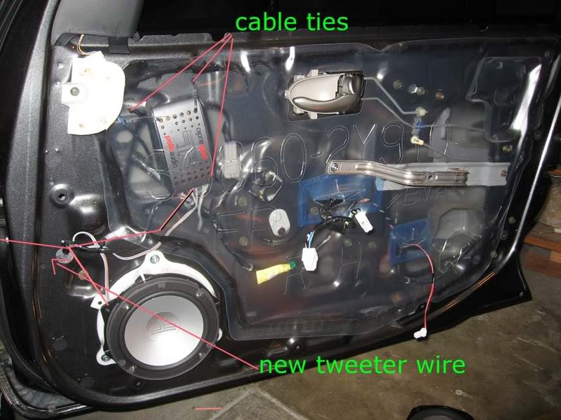
5. Here is another view of were the new wires go through.

6. Woofer install
The stock fronts seem to be 6.75″ because i had to use the brackets supplied from crutchfield. Attaching brackets to the white bezel is straight froward. I used the foam spacer between the bracket and the speaker
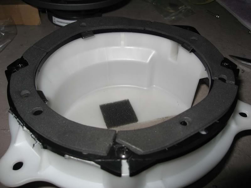
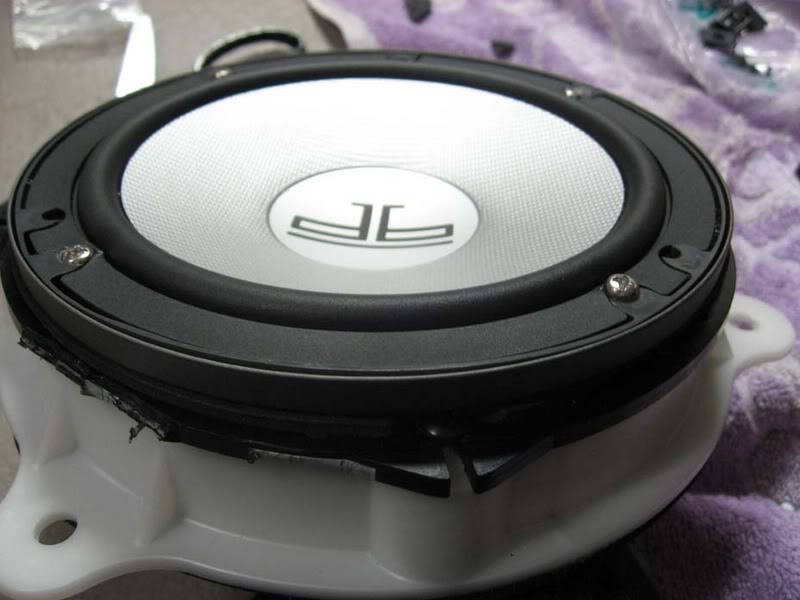
7. Again make sure everything works before re- instaling everything.
Additional Notes;
I. The stock signal goinng to the woofers was used for the cross-over.
II. Time to complete both front and rears was about 5 hours, includes taking pictures and figuring out best way to run all the wires. I had the most trouble finding a way to route the new tweeter wire. After figuring out one side, the other one was a piece of cake.
![]()
Member Credit: Jack Sulaiman & Geraldo Martin
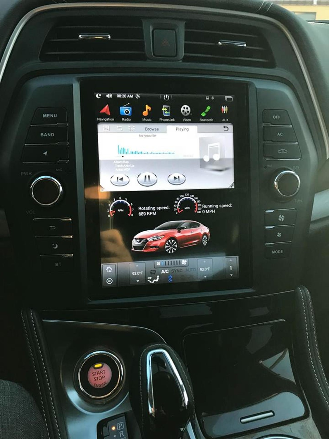
Price: $699.99
Other Notes:
Other Reported Issued by Jack:


![]()