Credit: phenryiv1
There have been lots of questions lately about this mod, so here are the facts as they pertain to 95-97. I am sure that they are the same for the 98-99.5, but my actual swap was in a 96. Also, these will work with an I30 or I30t, so long as you use a donor gauge set with the same odometer type (analog or digital, respectively).
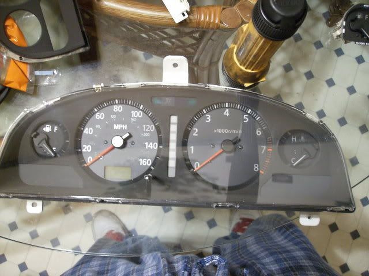
How does this go?
There have been issues and questions raised regarding the feasibility of a face-swap (between compatible years) so that odometer readings can remain true and accurate.
In the past, it was asked (by me) about whether or not the faces can be switched or whether the whole gauge must be transferred.
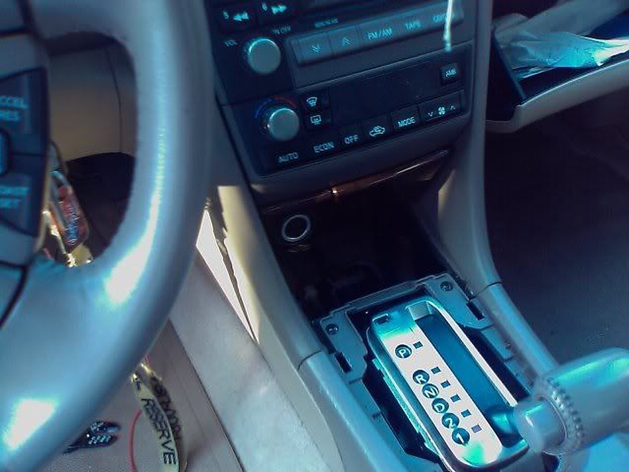
It was answered as to the 97-99.5 Maximas, but I can tell you without question that this CAN be done on the 95-96 versions as well. Because I have an auto and the donor cluster was a manual, I chose to keep my existing cluster.
NOTE: the issue here is regarding the loss of the “O/D OFF” light that the Manual gauge cluster does not have.
What are my choices on how to do this swap and how extensive my efforts should be?
If you want OEM SE faces, buy an OEM SE cluster. Now we all know about legality and odometer/ mileage problems. You have 3 choices:
1. You can switch the whole assembly and get an odometer adjustment statement. Pros- EASY. Cons- Can lower resale value because an odometer adjustment statement will be attached to the title.
2. You can switch the whole assembly and NOT get an odometer adjustment statement. Pros- EASY. Cons- Illegal. If the mileage is LOWER, it is definitely illegal; if it is higher it is not illegal UNLESS you go back to the original cluster to sell the car. If you change the mileage on a car to a lower amount, it is odometer fraud, unless you get the aforementioned odometer disclosure statement.
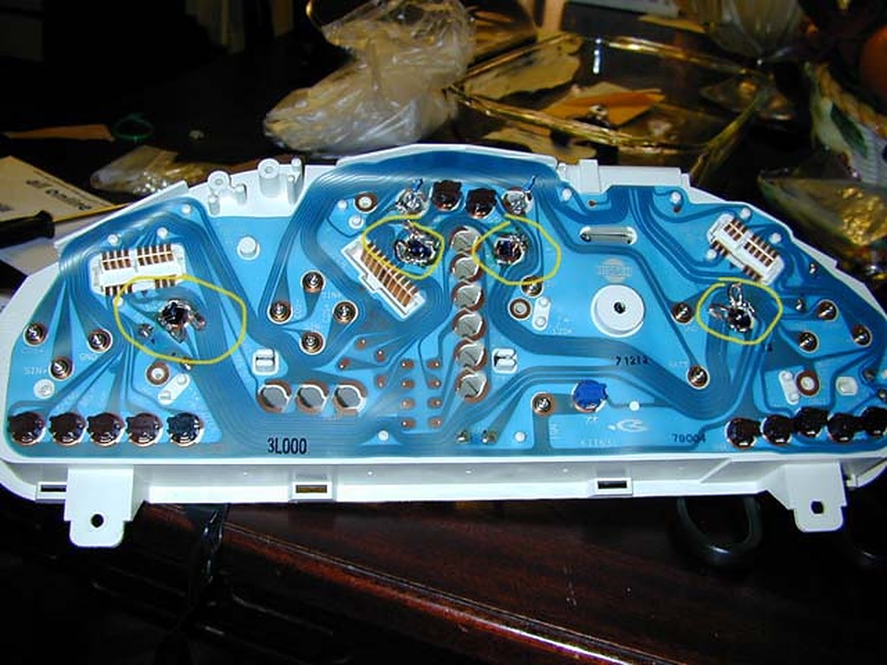
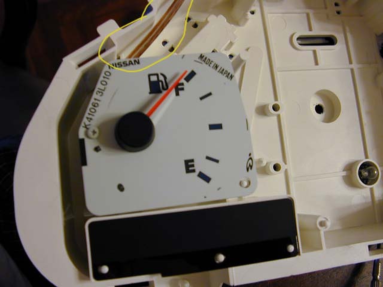
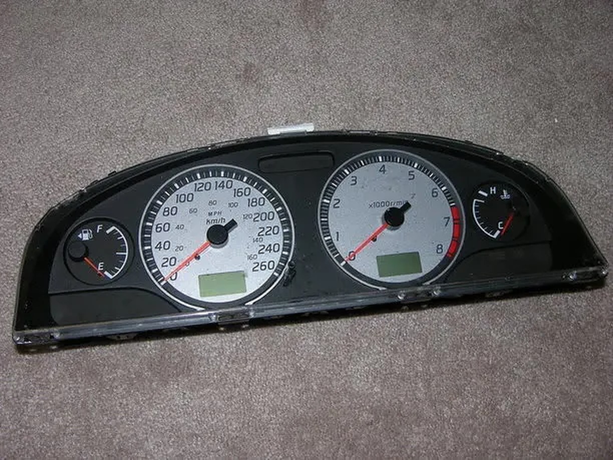
3. (What I did) Switch the fuel gauge, temp gauge, and tachometer. Actually, you REUSE only the Speedo- everything else is from the new gauge cluster.
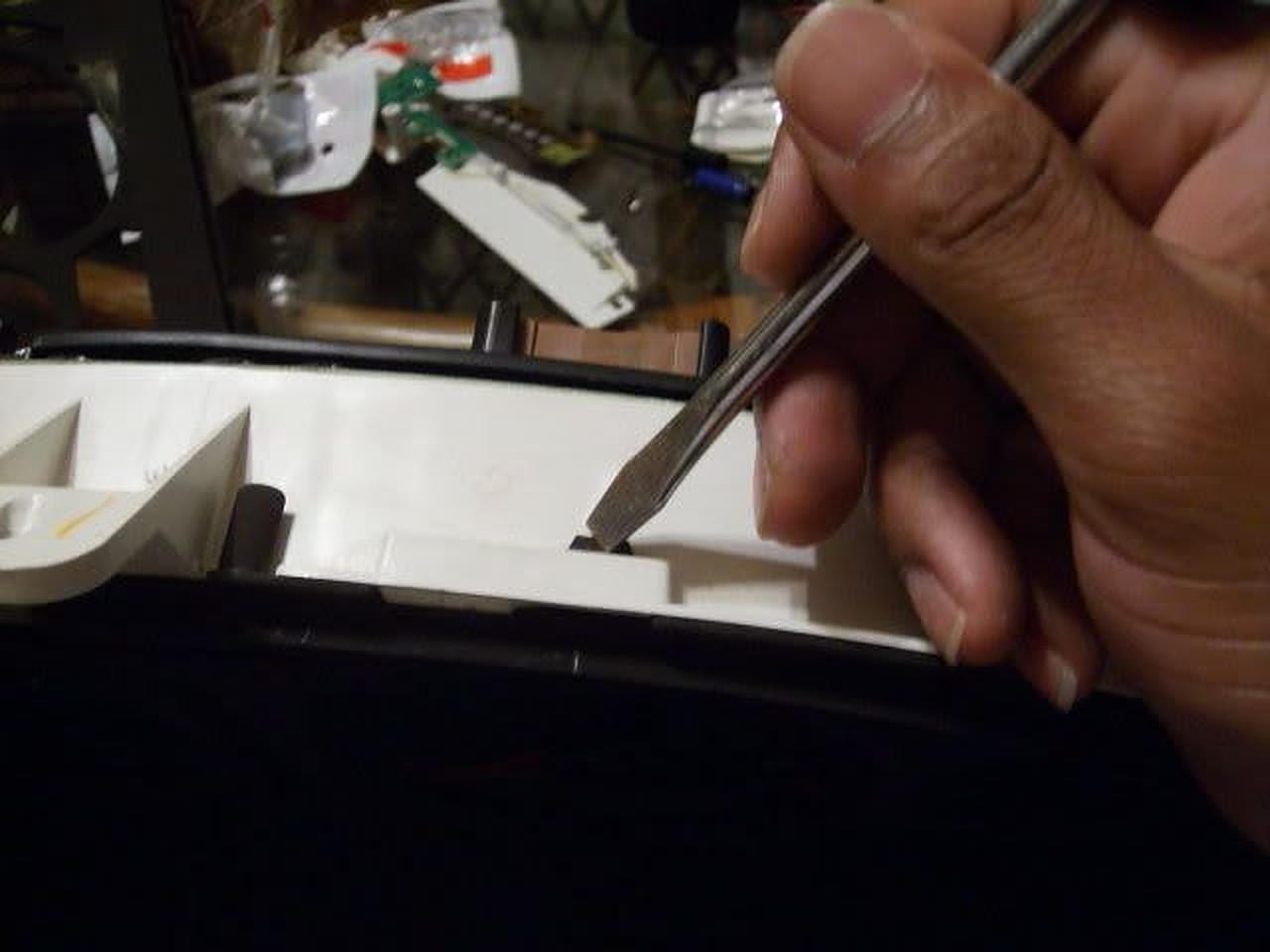
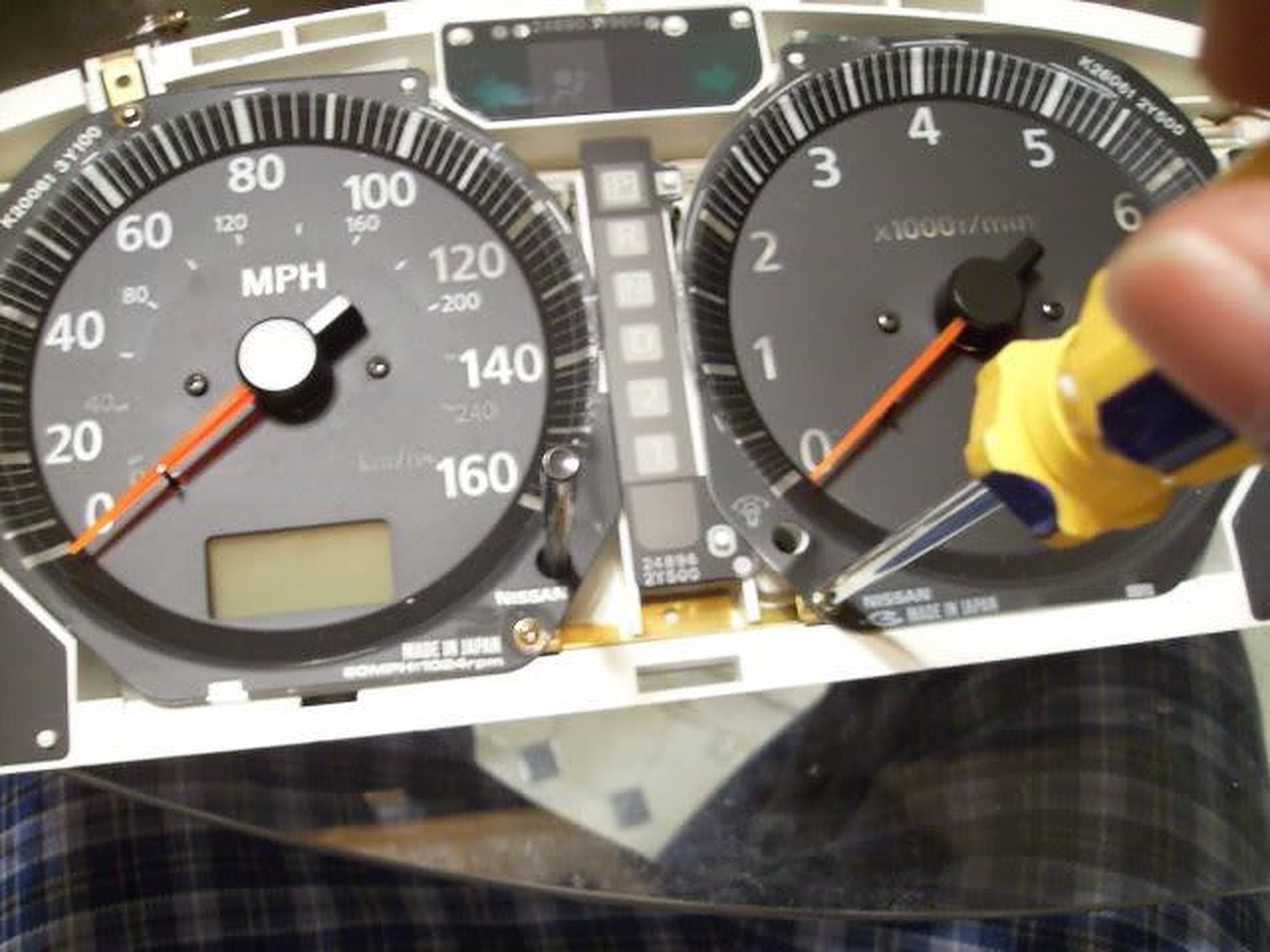
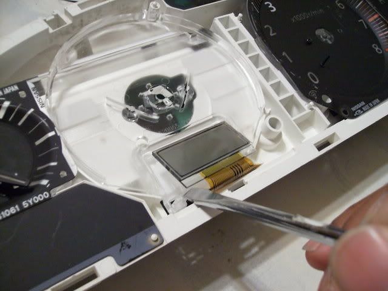
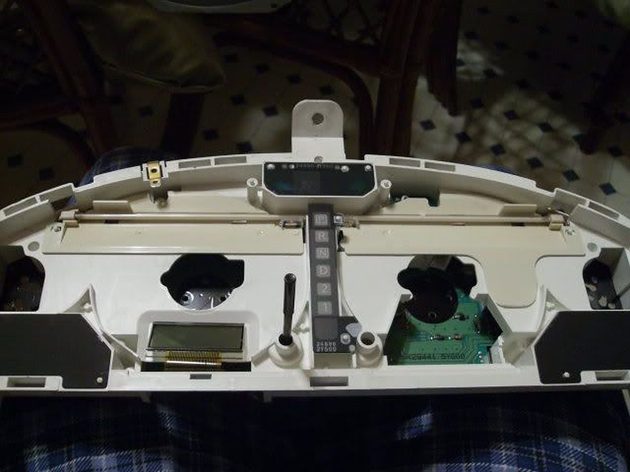
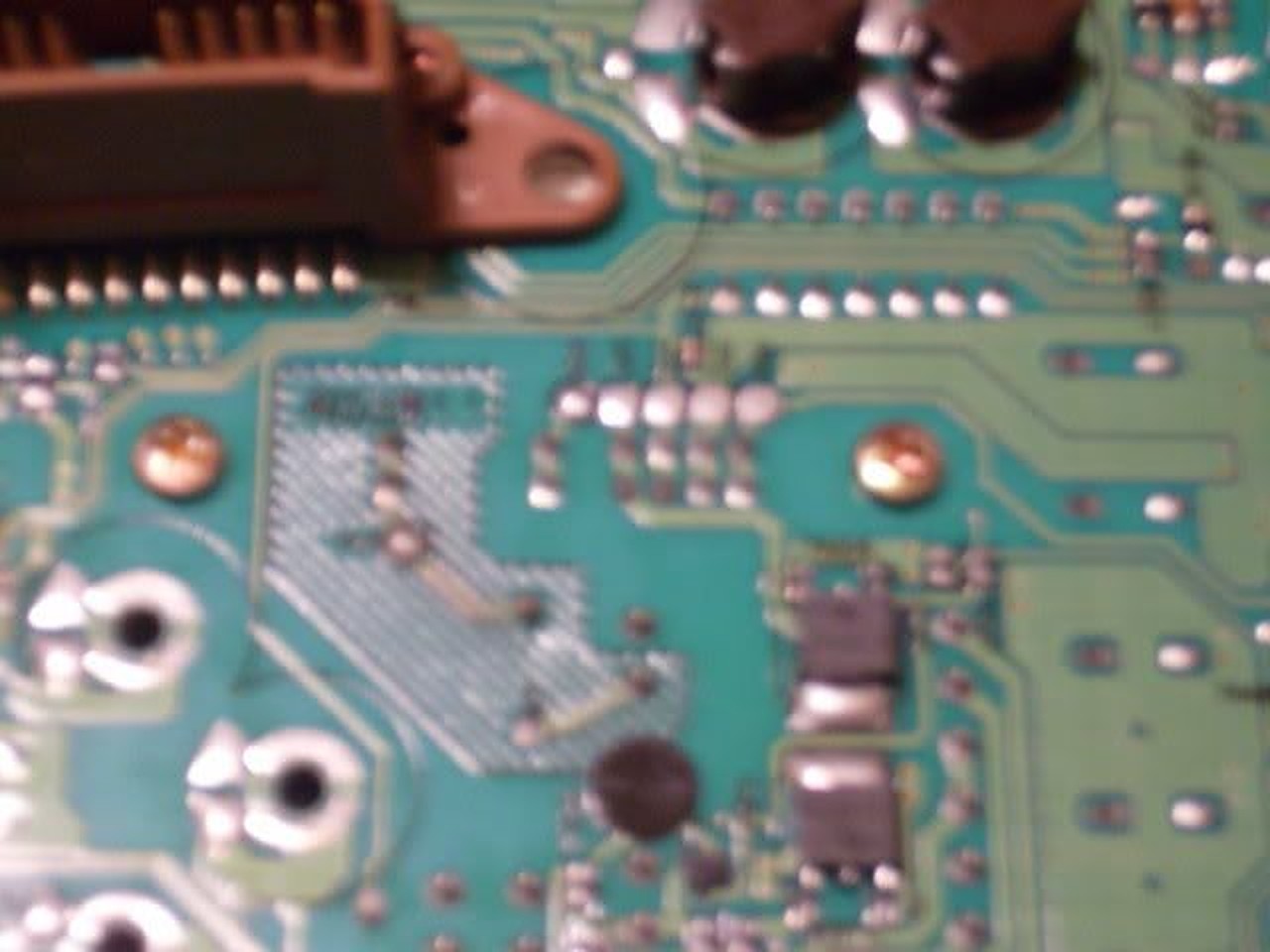
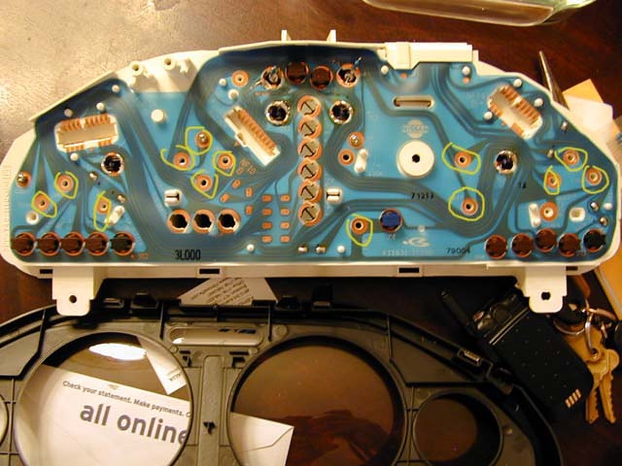
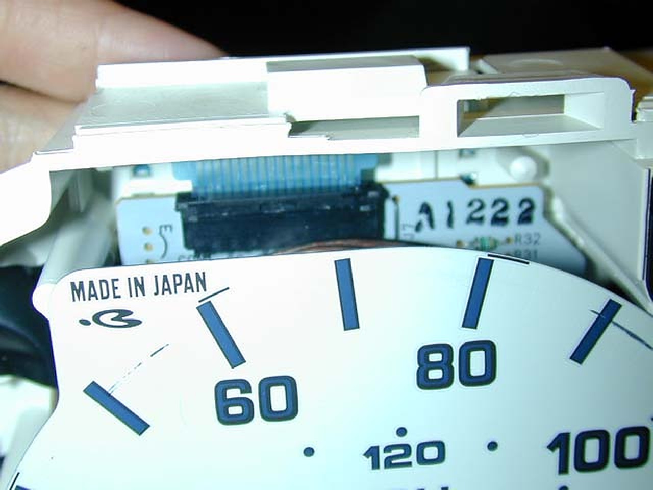
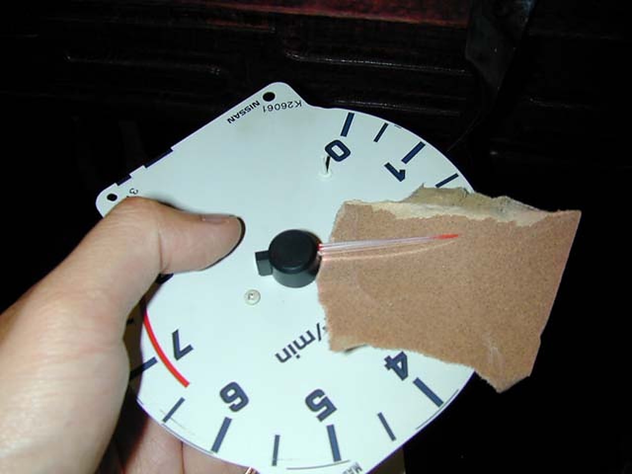
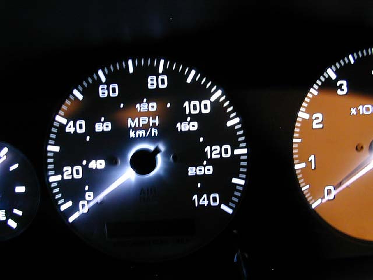
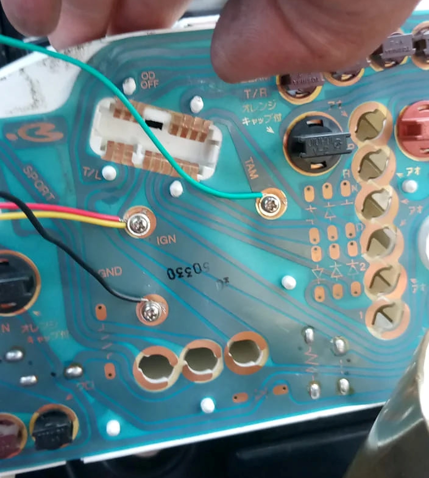
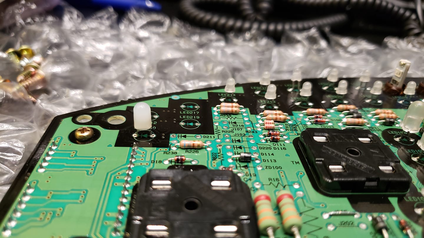
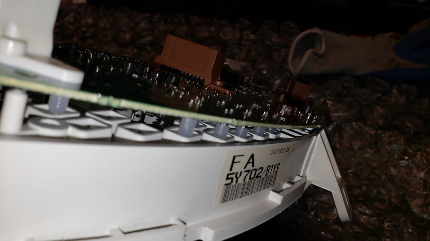
Take the odo/speedo gauge and remove it from the GLE/GXE cluster. You will be reusing the base from your GLE/GXE. Remove the needle and the face. Take the needle and the face off of the SE. CAREFULLY drill out the 2 screw holes that the GLE has but the SE lacks (see below and PM/email me for more info about this). Put the SE face on your old GLE/GXE gauge base. Reuse the SE needle. This will have your original odometer in your car, thus making it 100% legal.
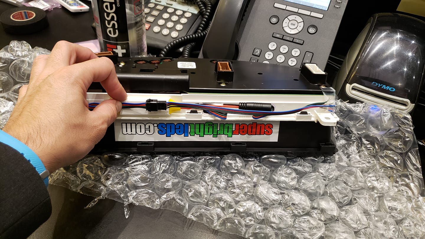
So on to my actual swap:
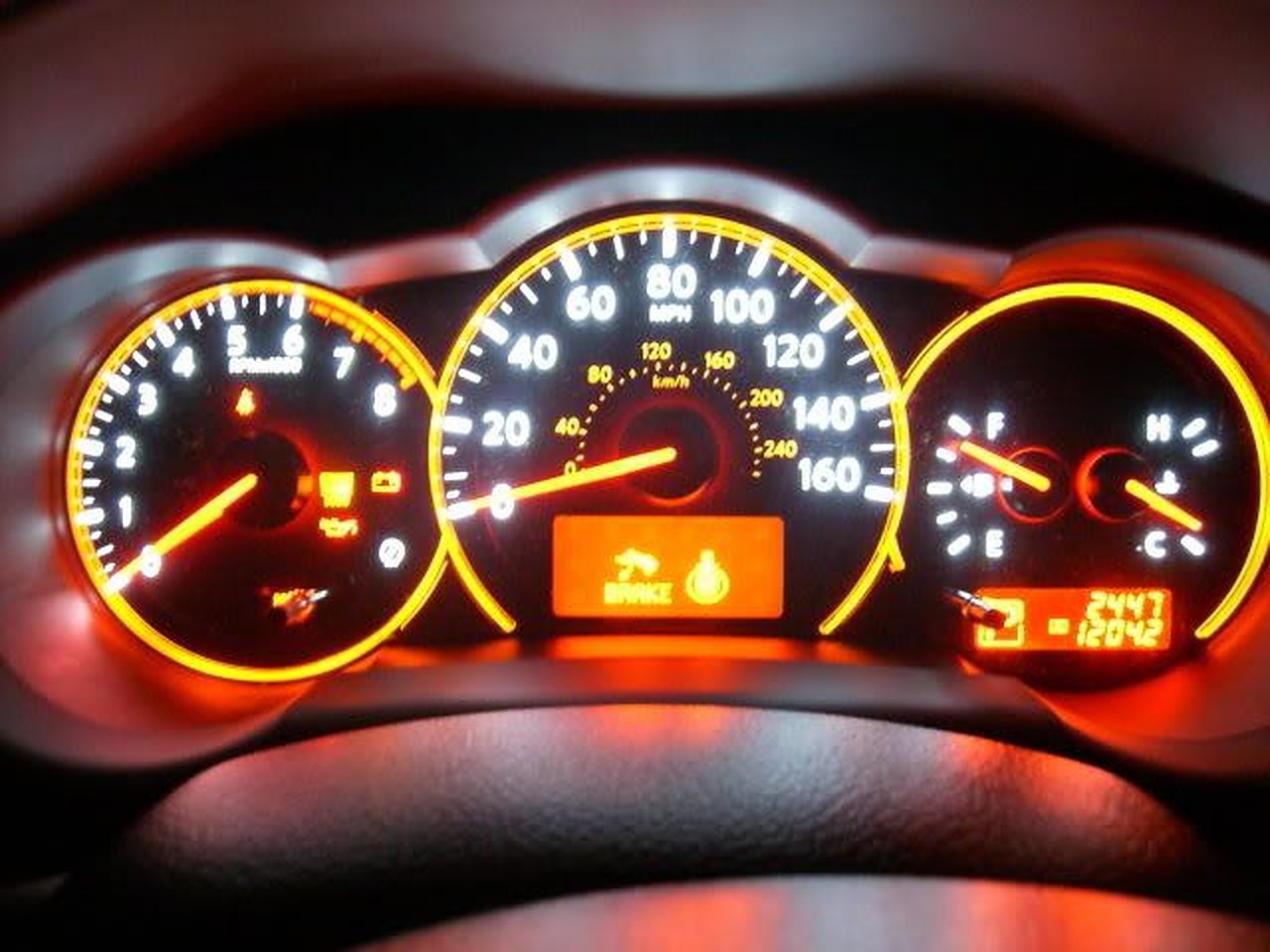
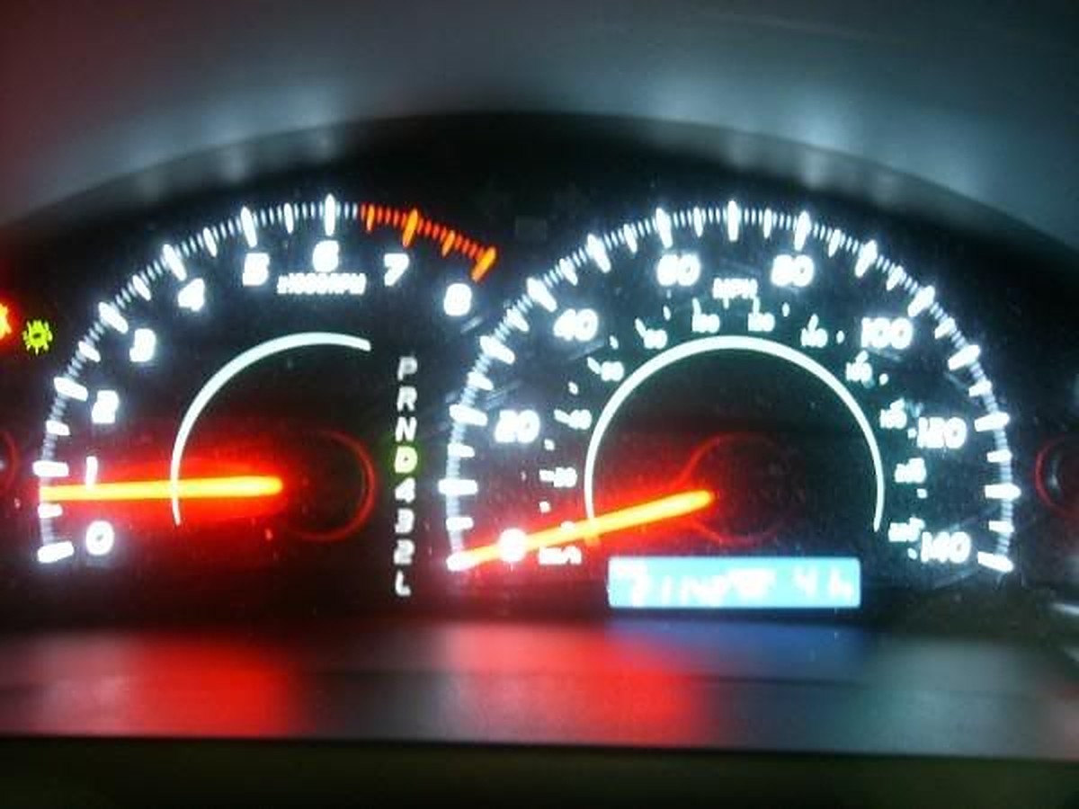
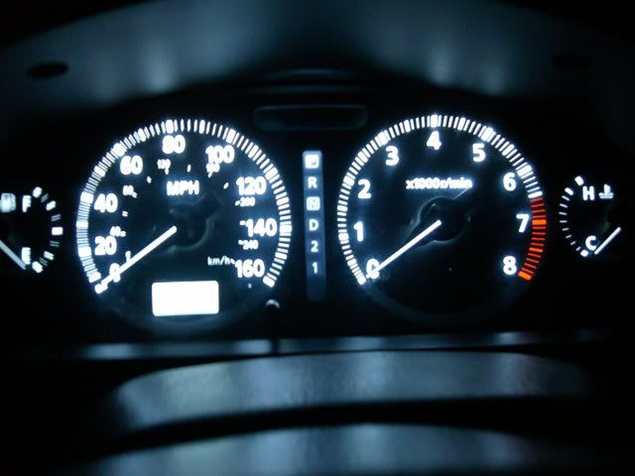
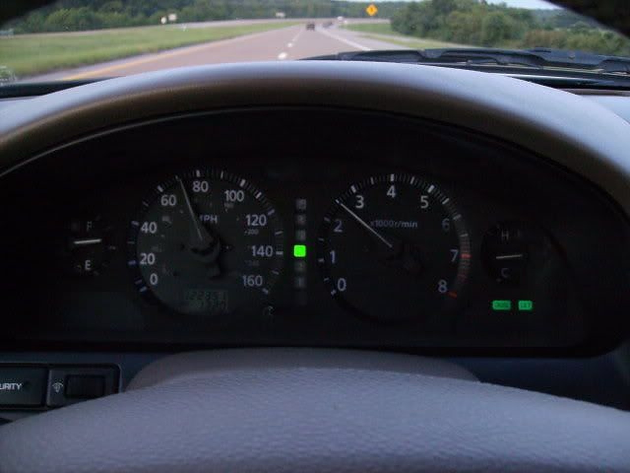
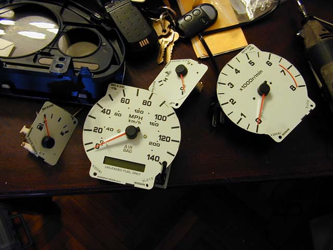
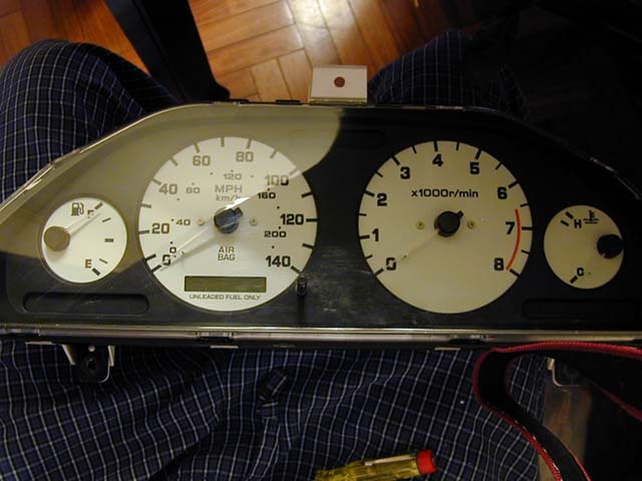
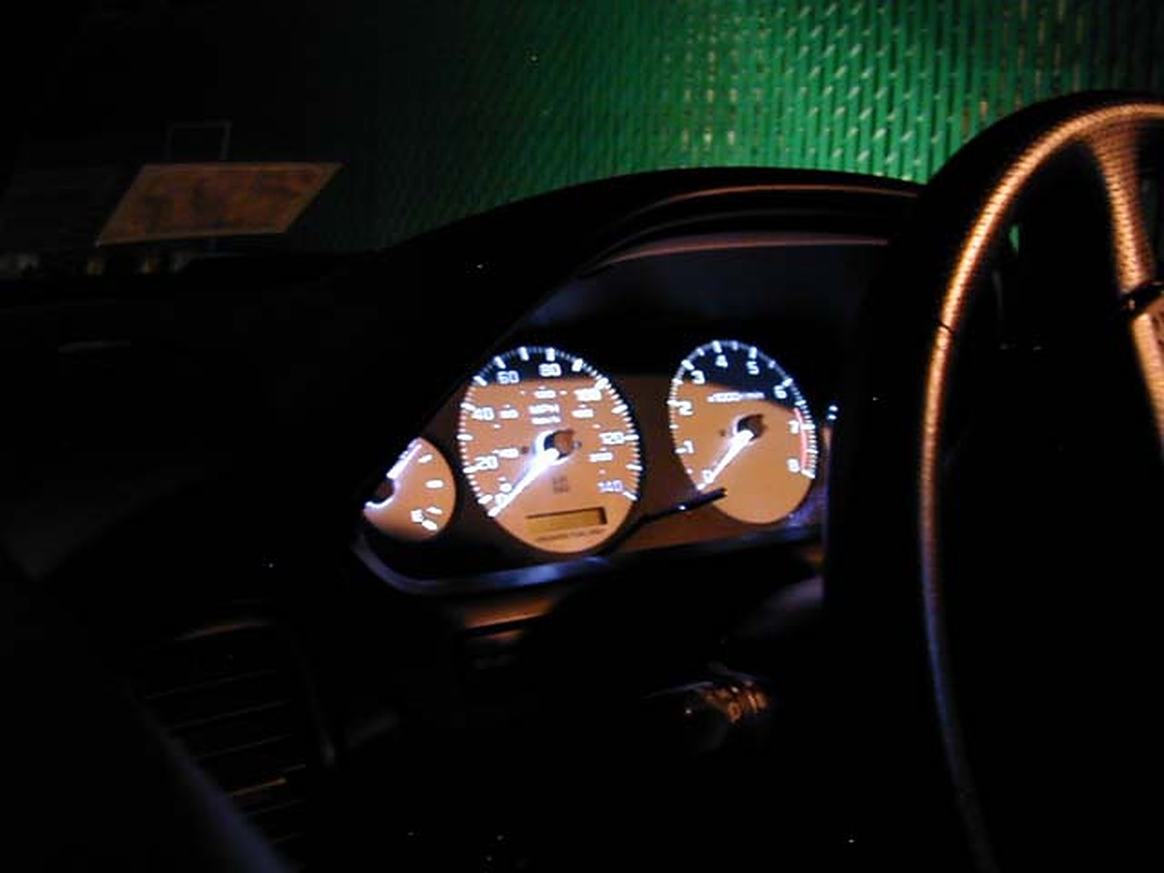
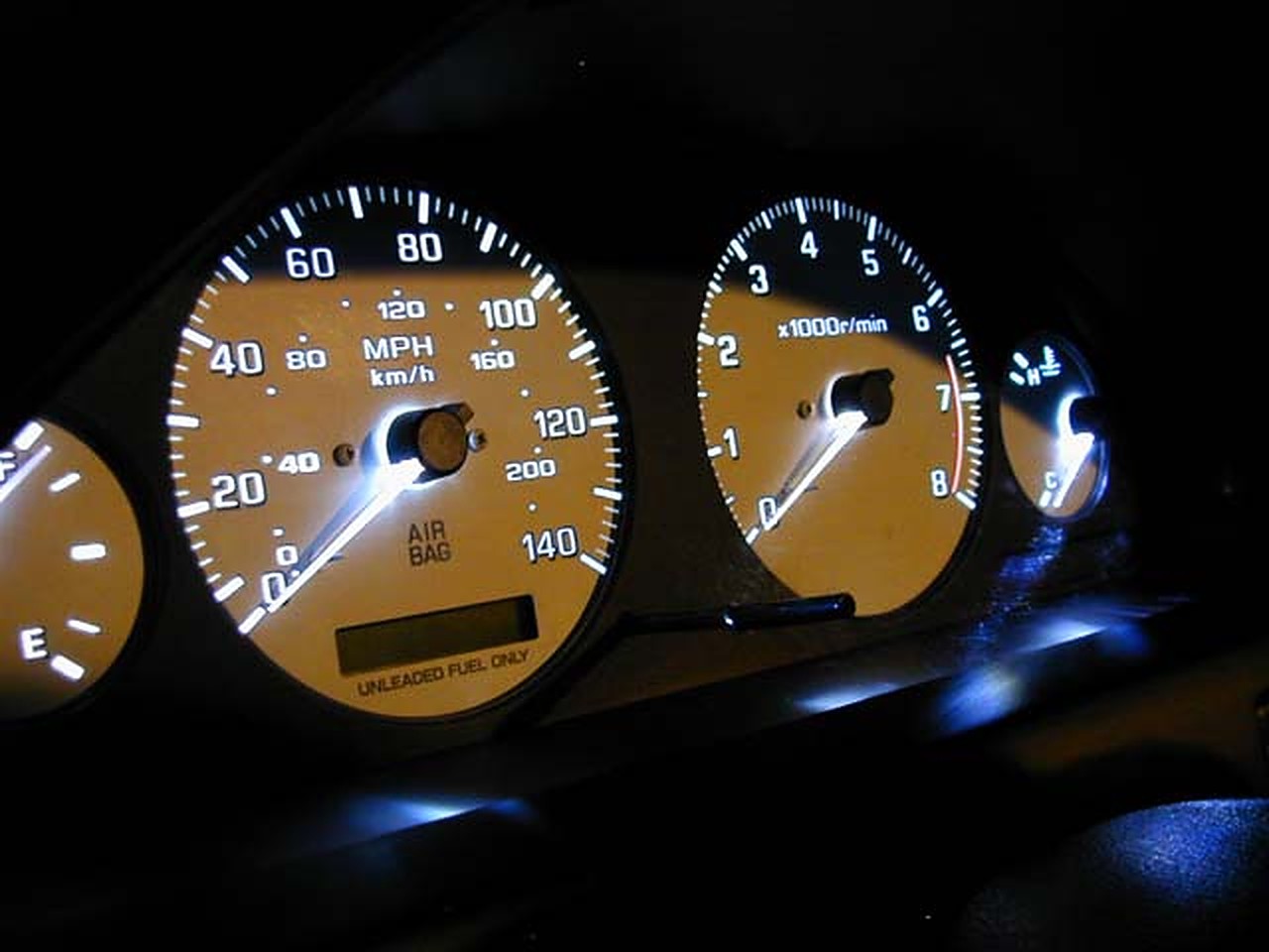
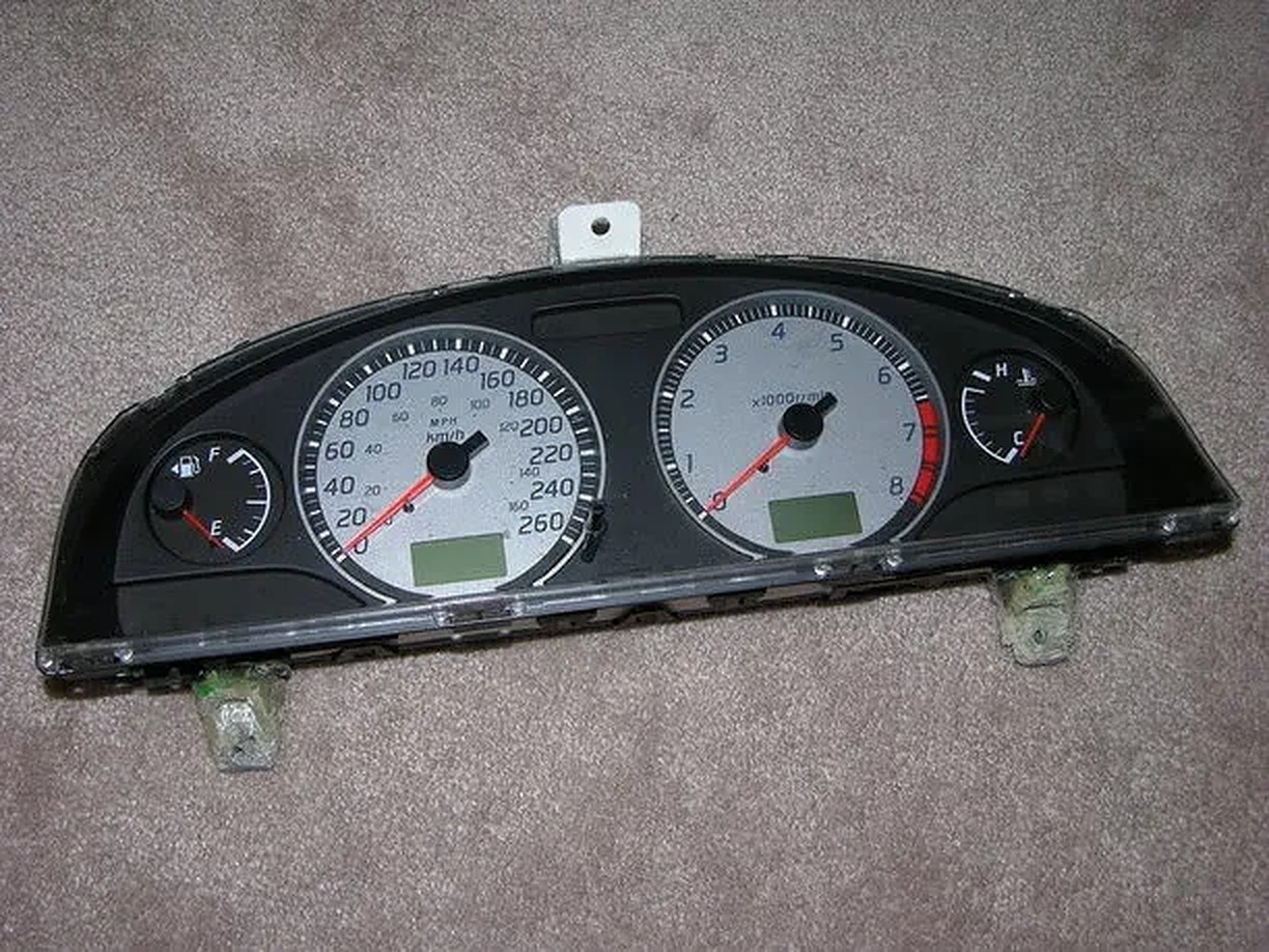
The donor sent me the FULL gauges for tach, temp, and fuel (faces AND electronics), and for the speedo he sent only the face and the needle rest. He broke the needle doing the removal of the face, so I had to ask around. He was also cool enough to send me an SE needle to go on the face of the white SE gauge (my white GLE needle would not have shown up). My temp, tach, and fuel gauges have white/black needles, and the speedo has orange. Oddly enough, I LIKE this, b/c it makes the speedo easier to see at a glance. If I was a racer or had a manual, I would want this needle on the tach, but I have an auto so it works best on he speedo.
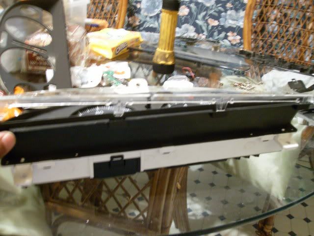
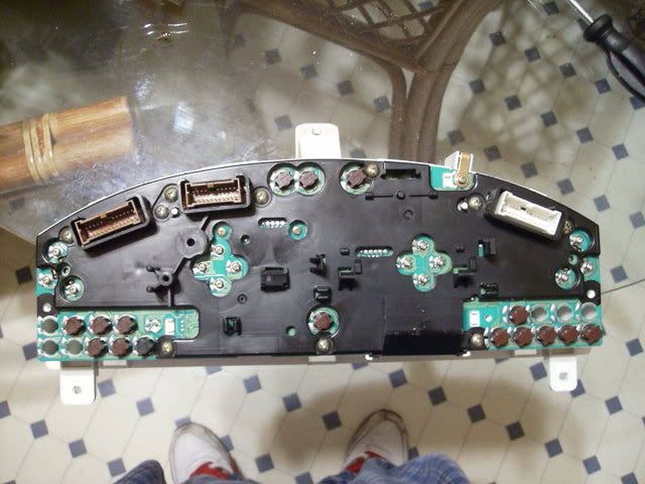
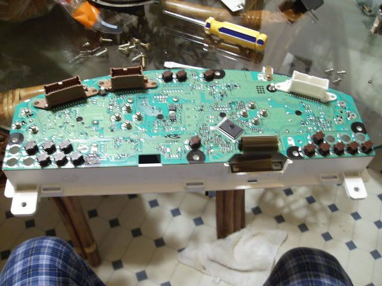
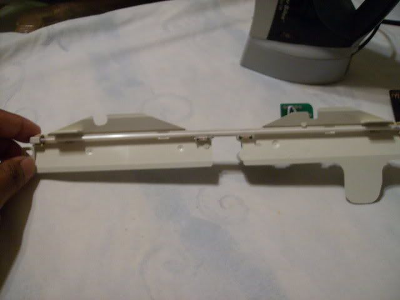
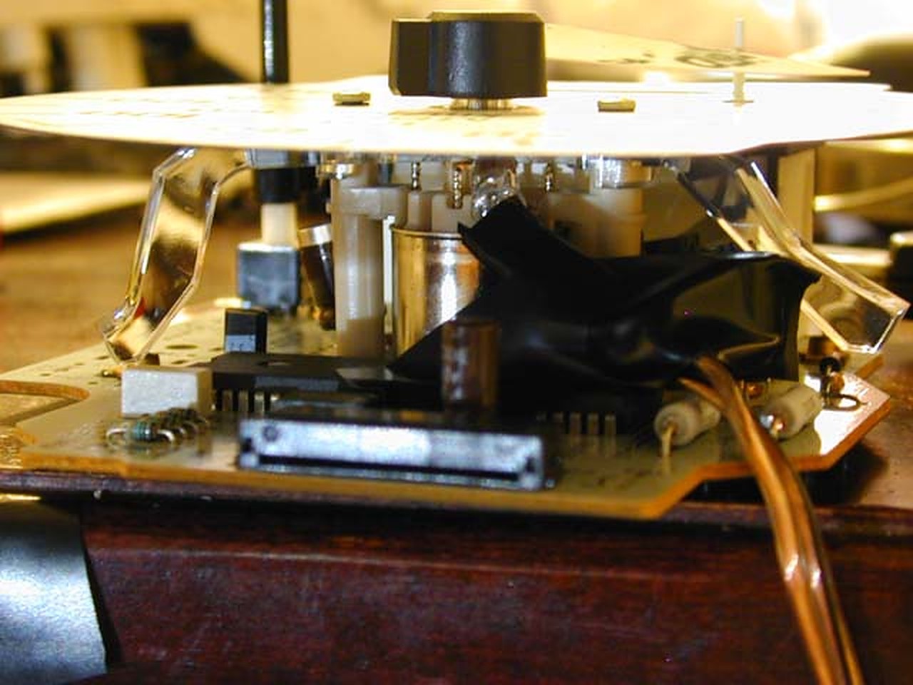
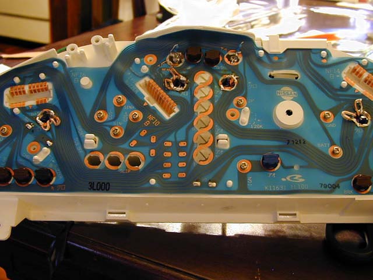
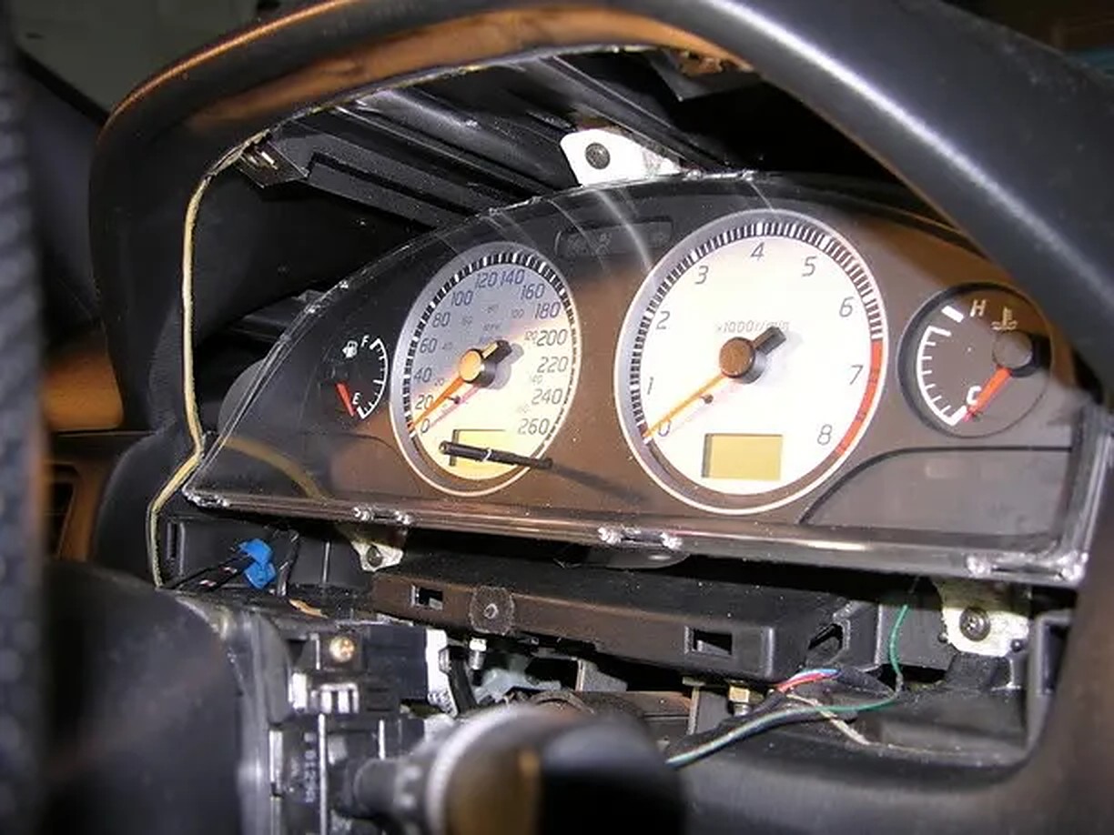
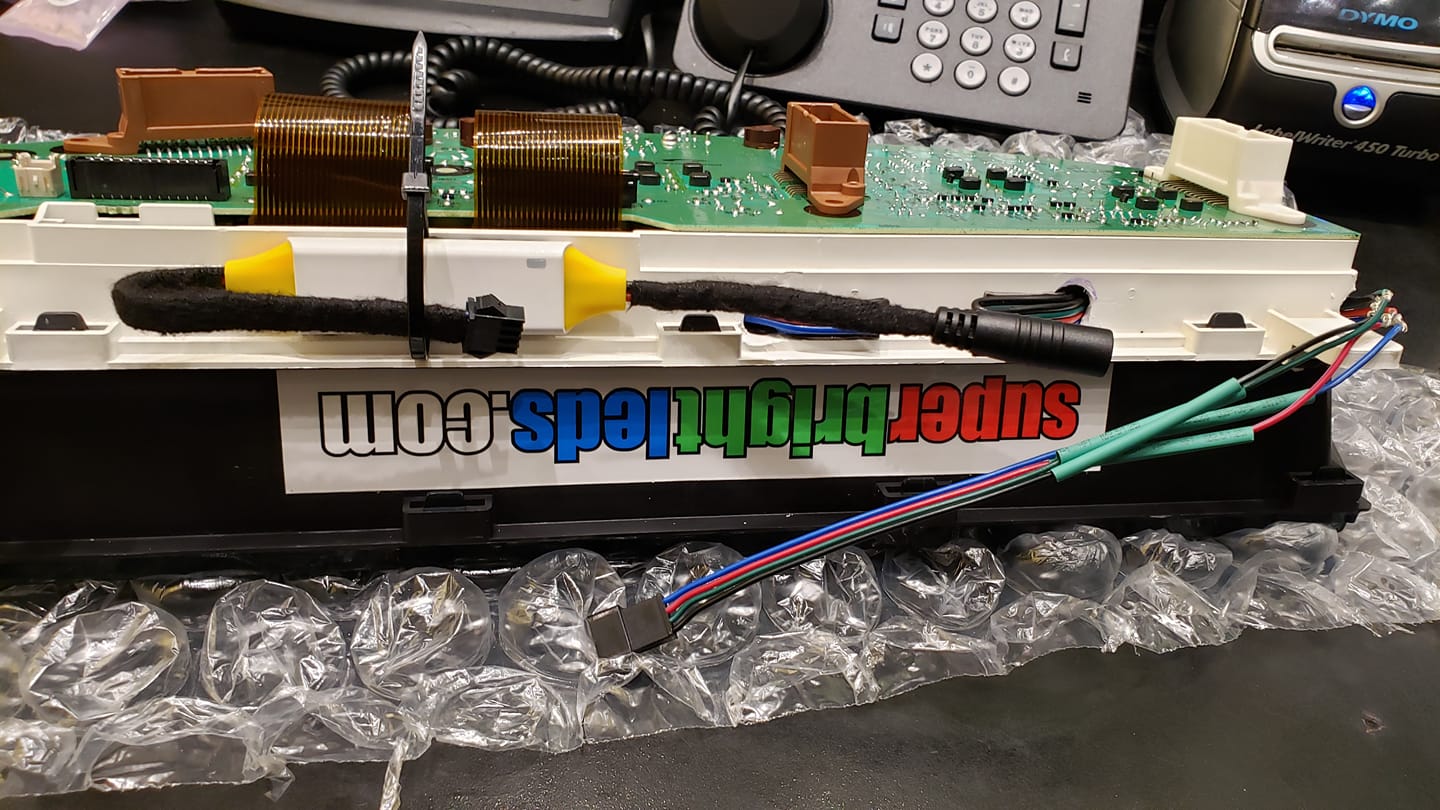
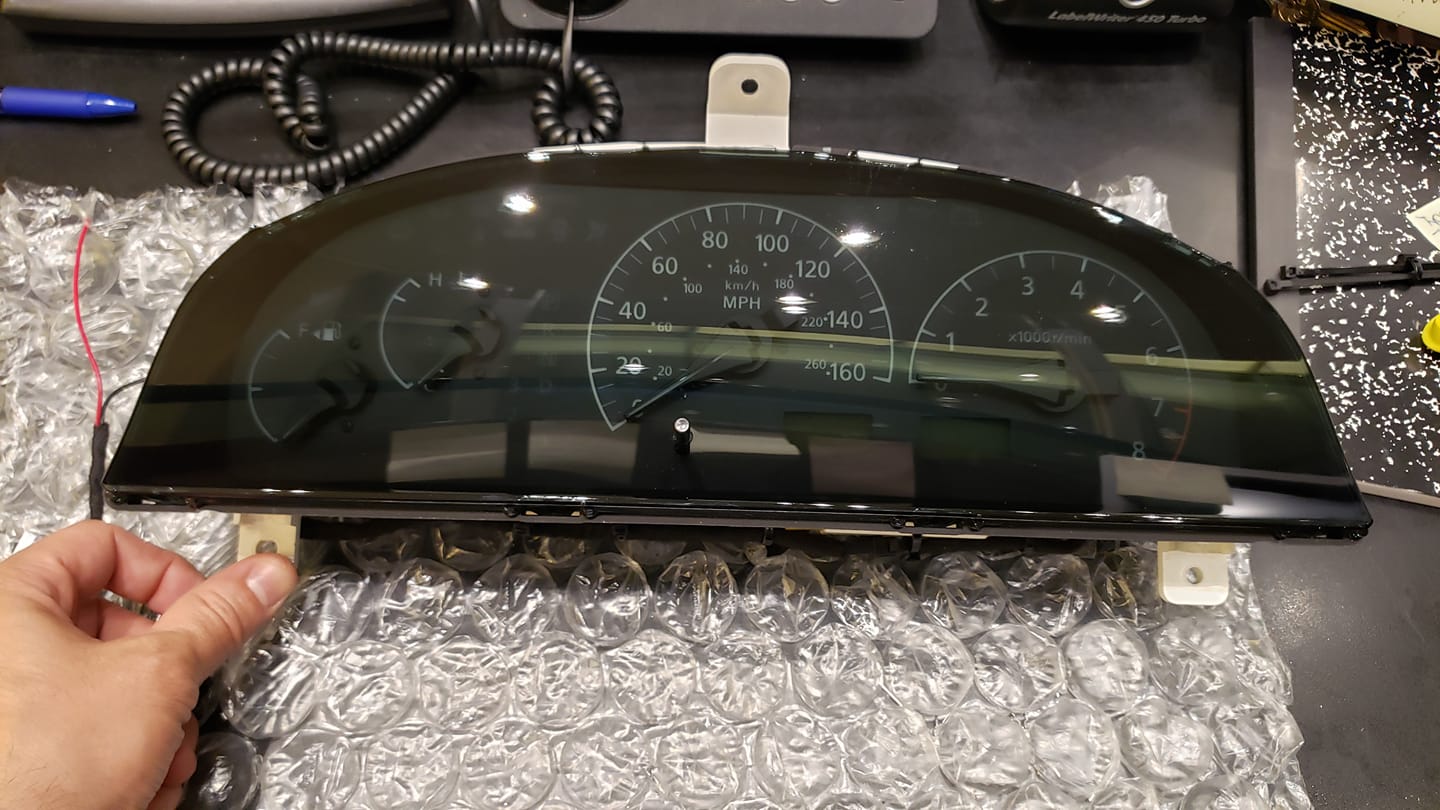
I swapped the WHOLE gauge (face and electronics) into my cluster base for the temp/tach/fuel (3 easy screws each), and did a face swap on the speedo/odo cluster. 2 extra screws, plus the needle swap, and it was done. Like the link above says, I had trouble with the needle sticking, but it was resolved. Read this thread to see problems encountered when the needles stuck after the gauge face swap.
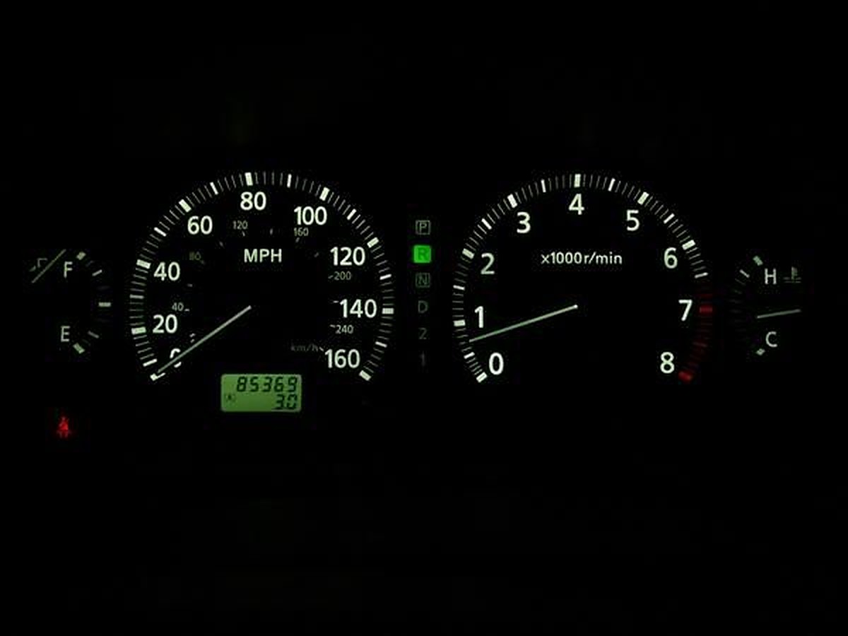
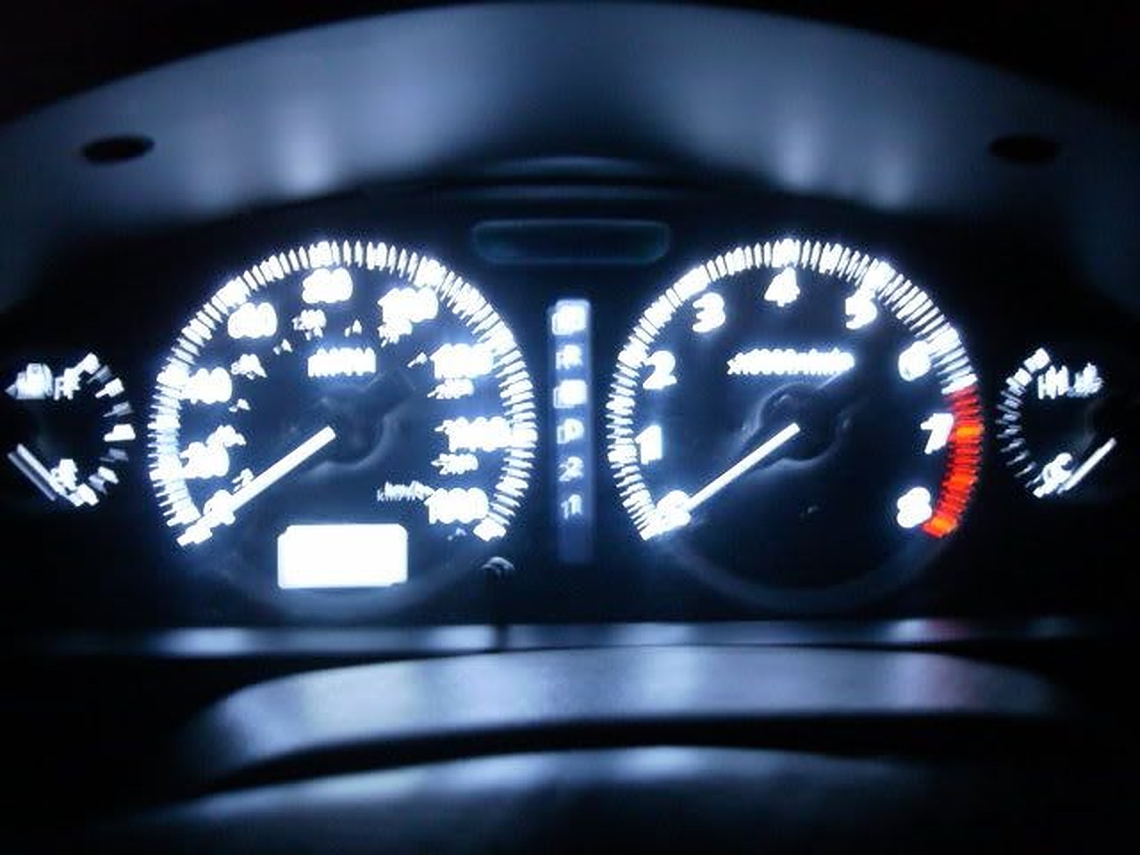
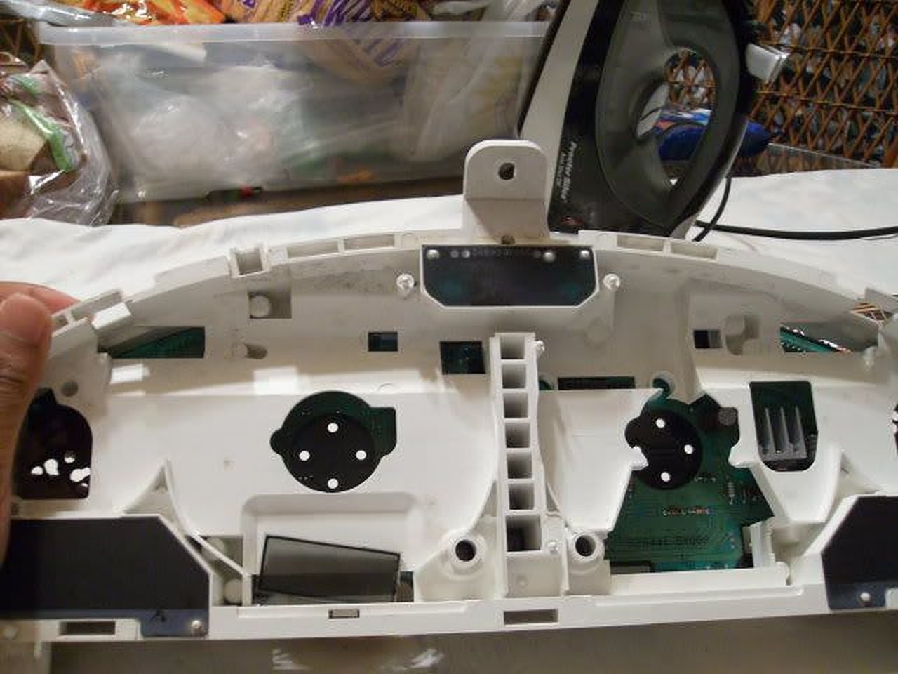
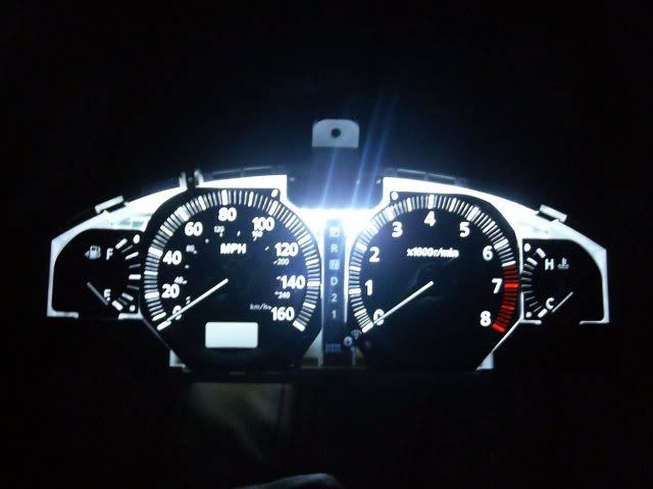
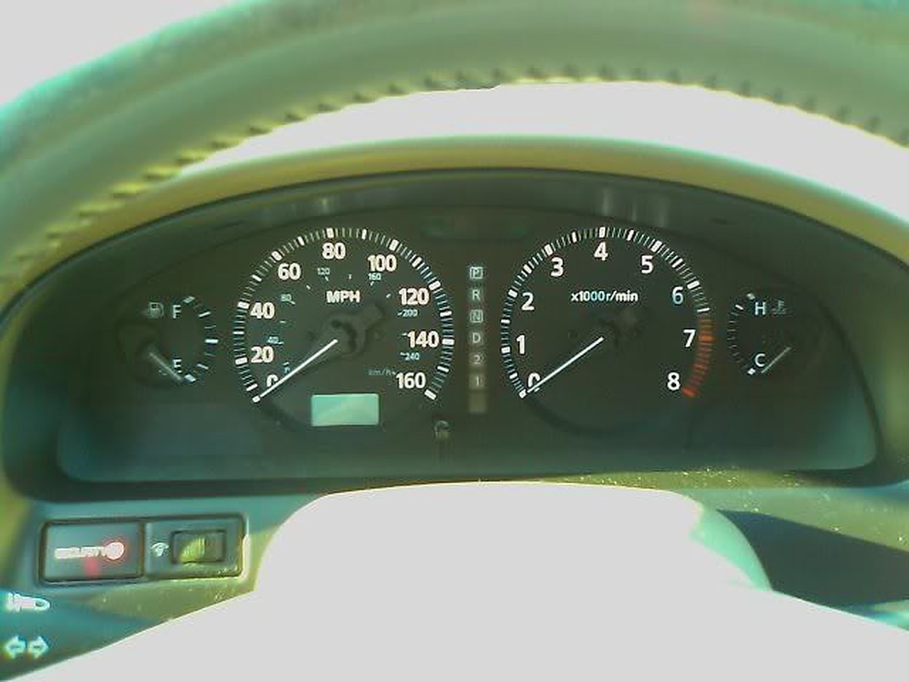
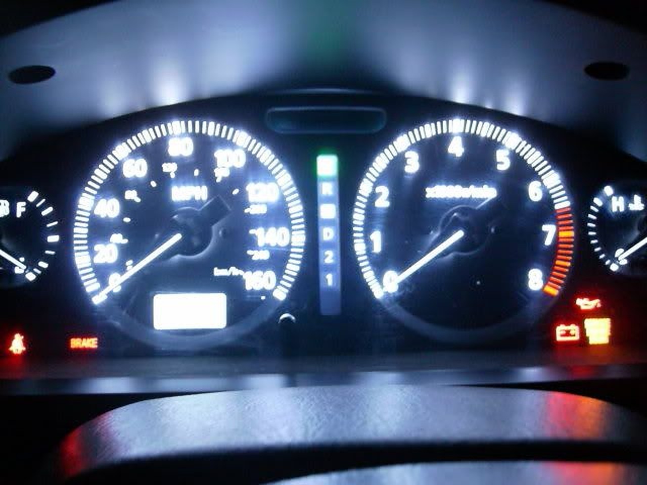
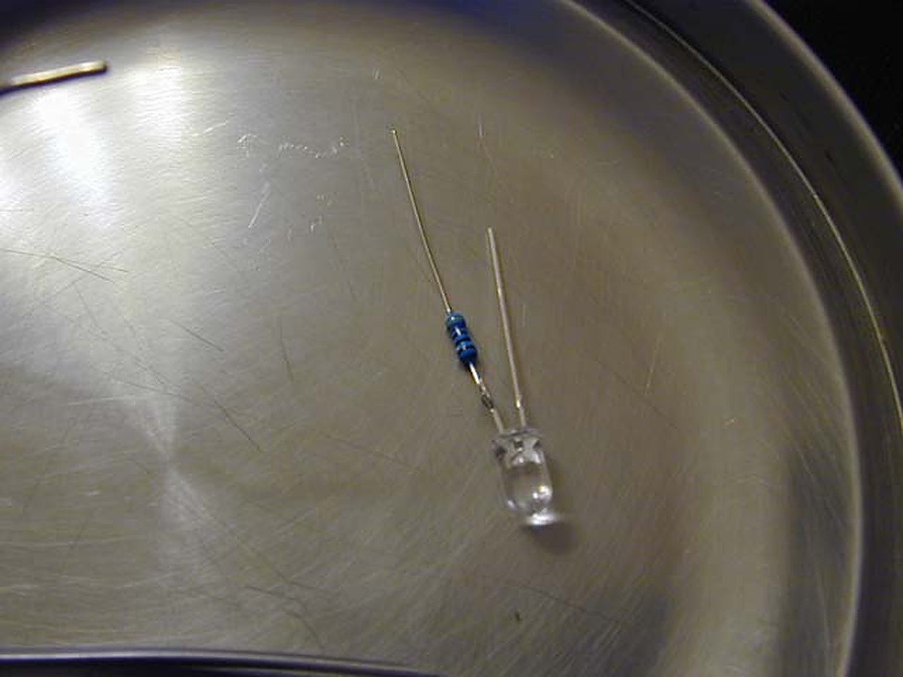
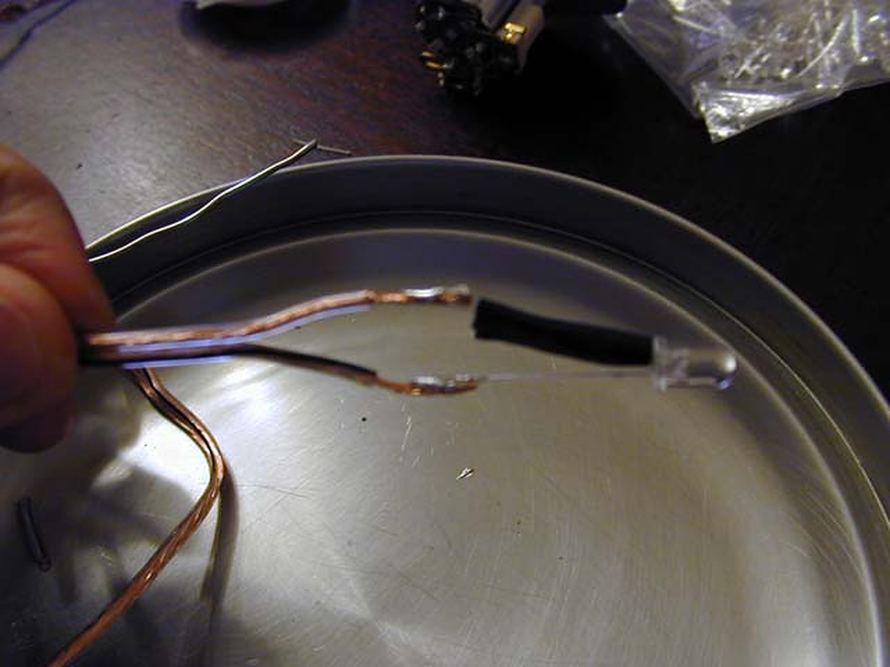
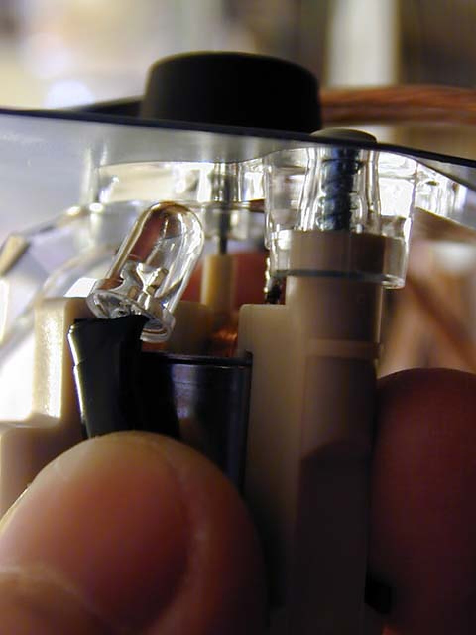
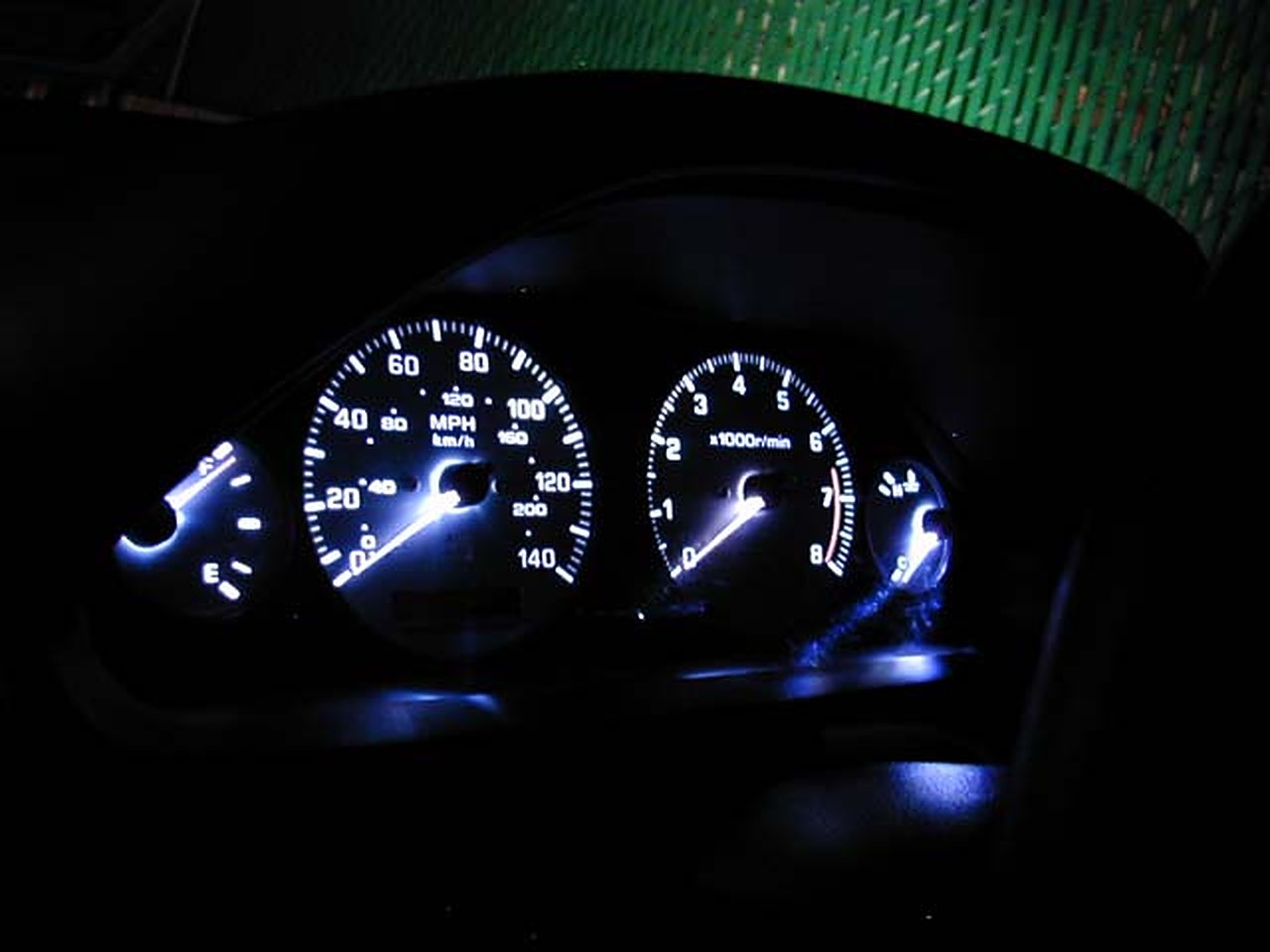
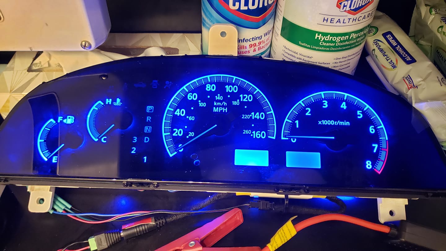
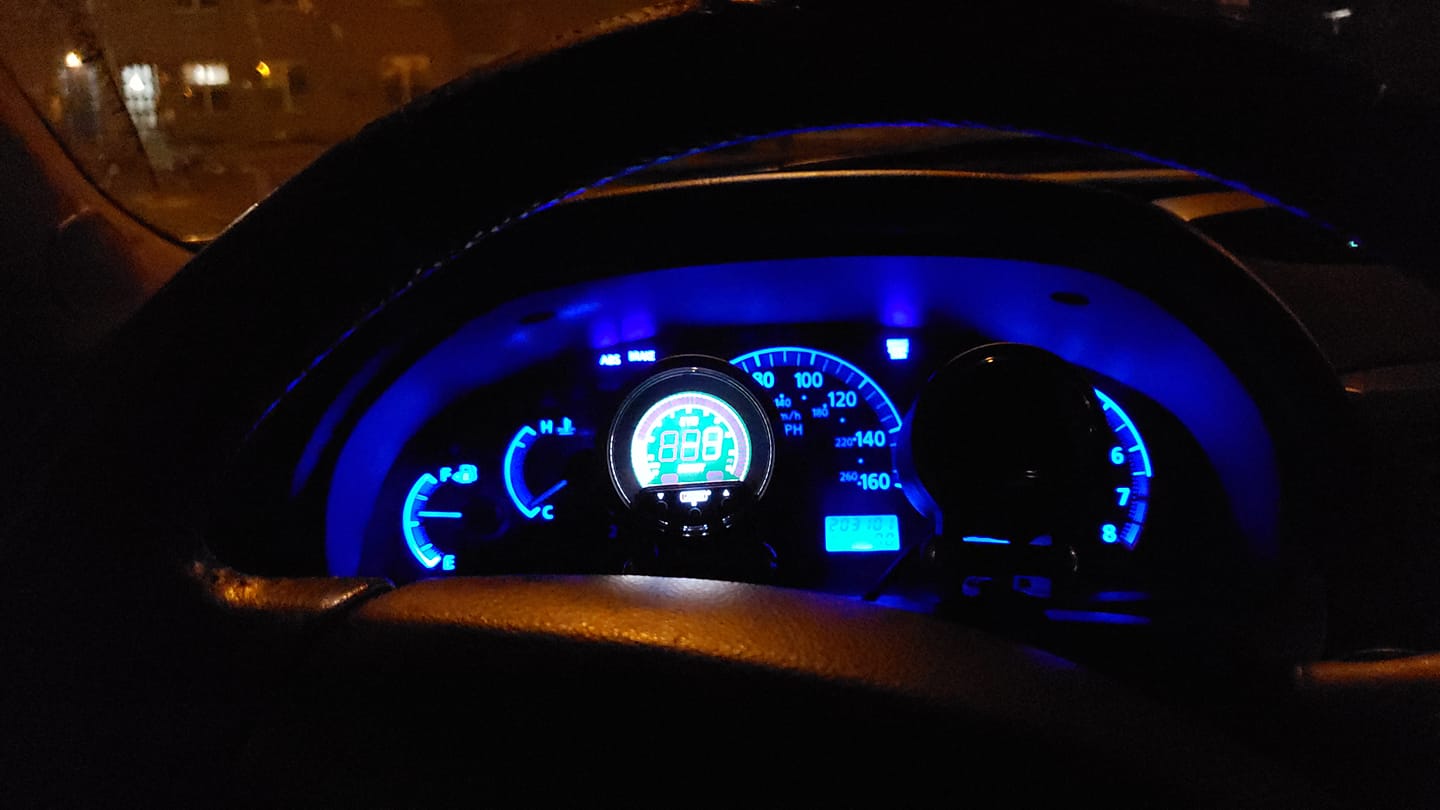
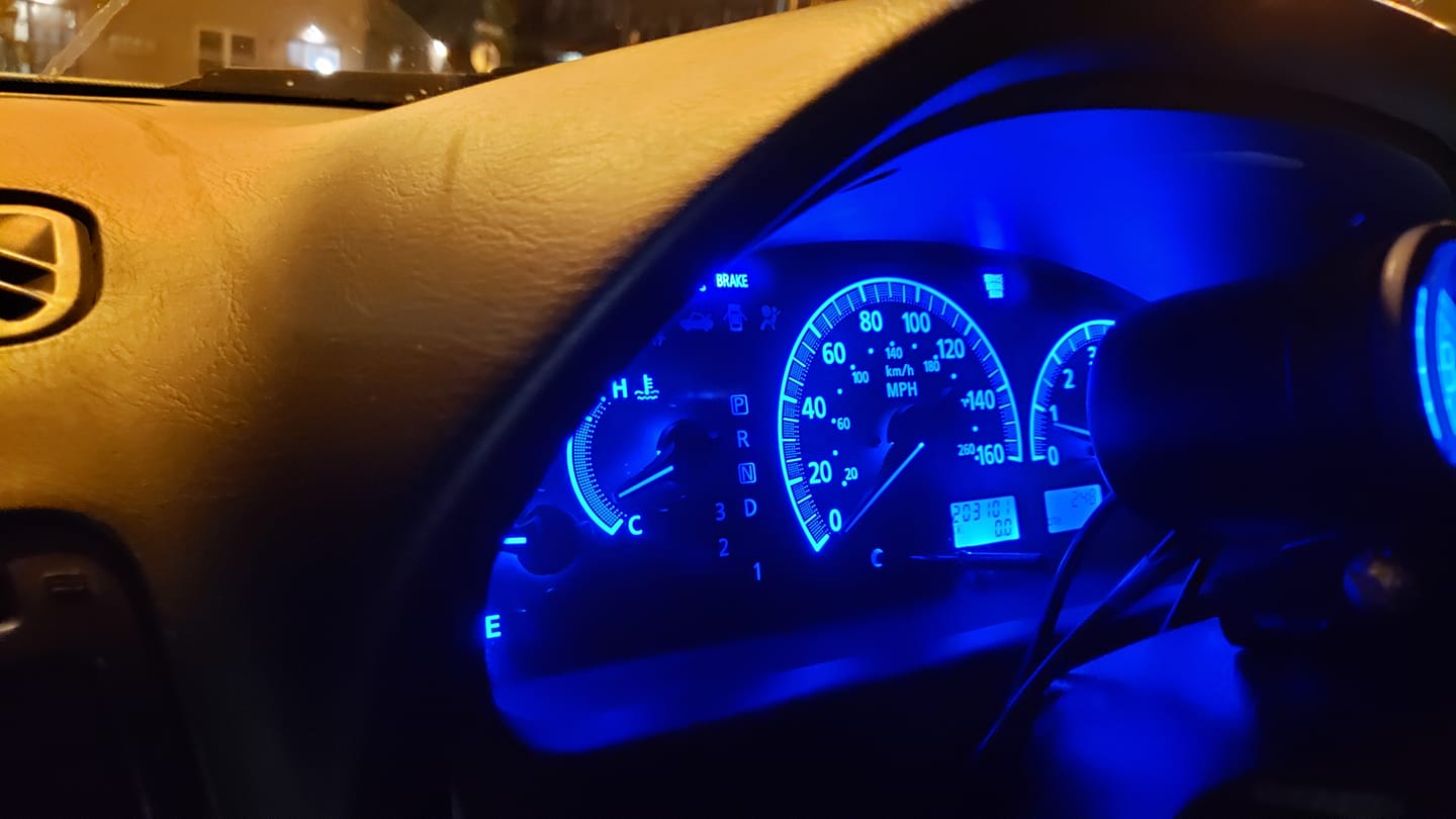
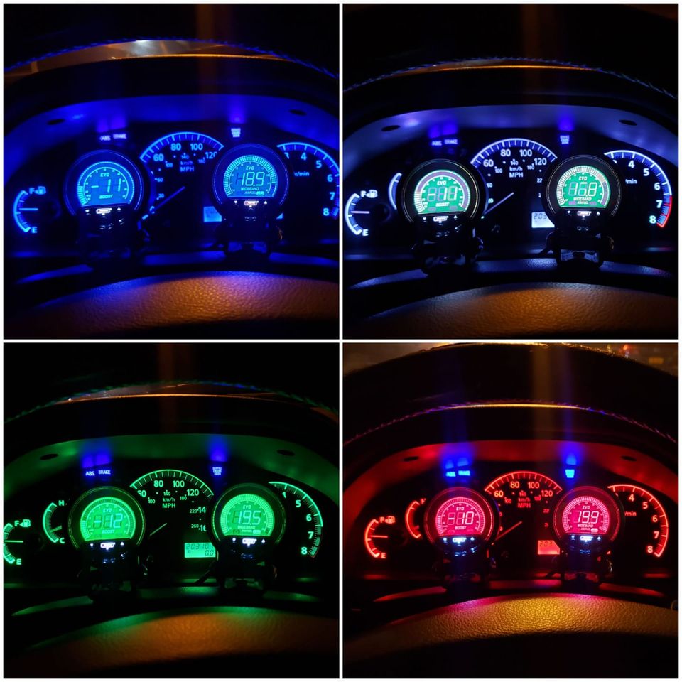
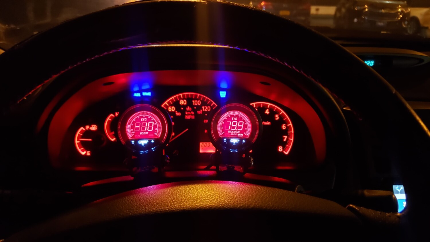
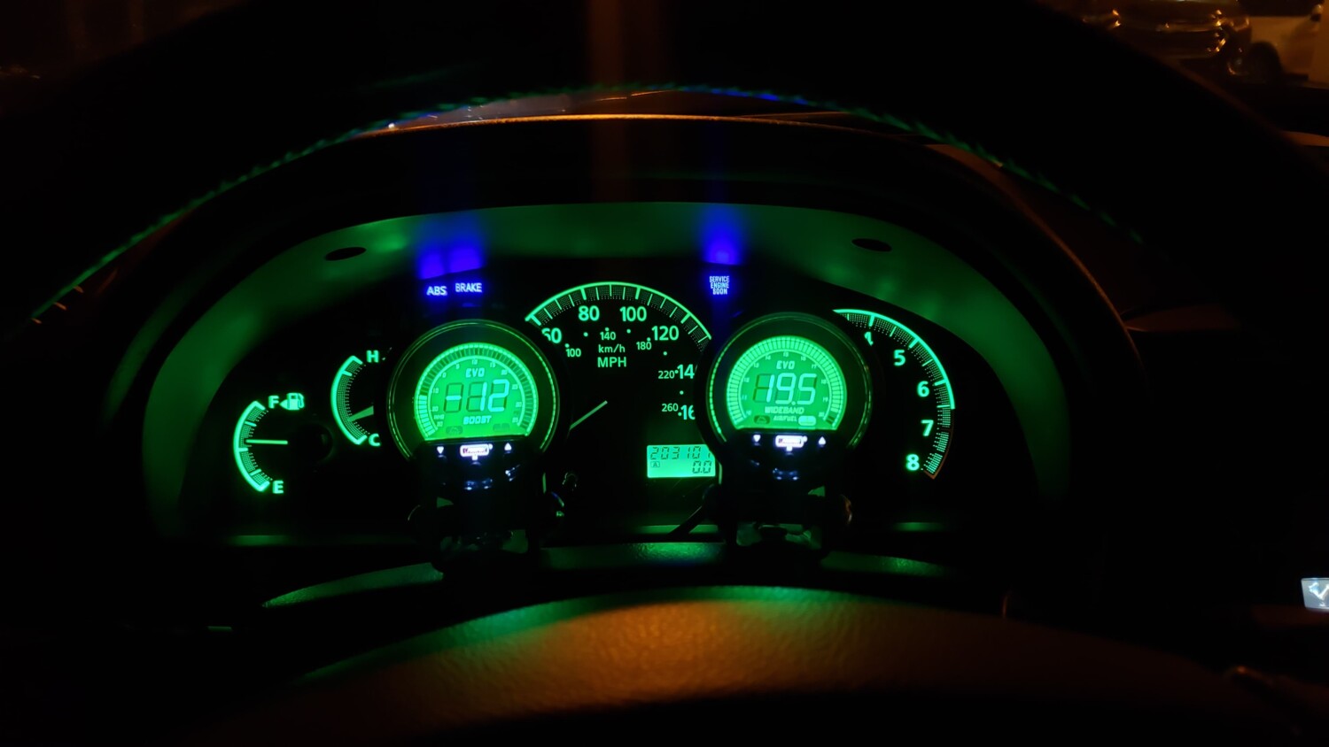
While the gauges were out I switched the dash illumination bulbs (5 total) from white to red. These look great, are super deep, and light up just bright enough. Even if I was not doing the face-swap, these bulbs would have been worth the time. I wanted blue, but have used blue 194s before and cannot find ones that do not fade over time. After the mixed reviews on 194-based LEDs (1 or 4 LED versions), I have decided to stick w/ the reds. I actually looked for VW OEM blurple/indigo bulbs, but they are not sold to the public (they are soldered to the dash cluster).

![]()


")


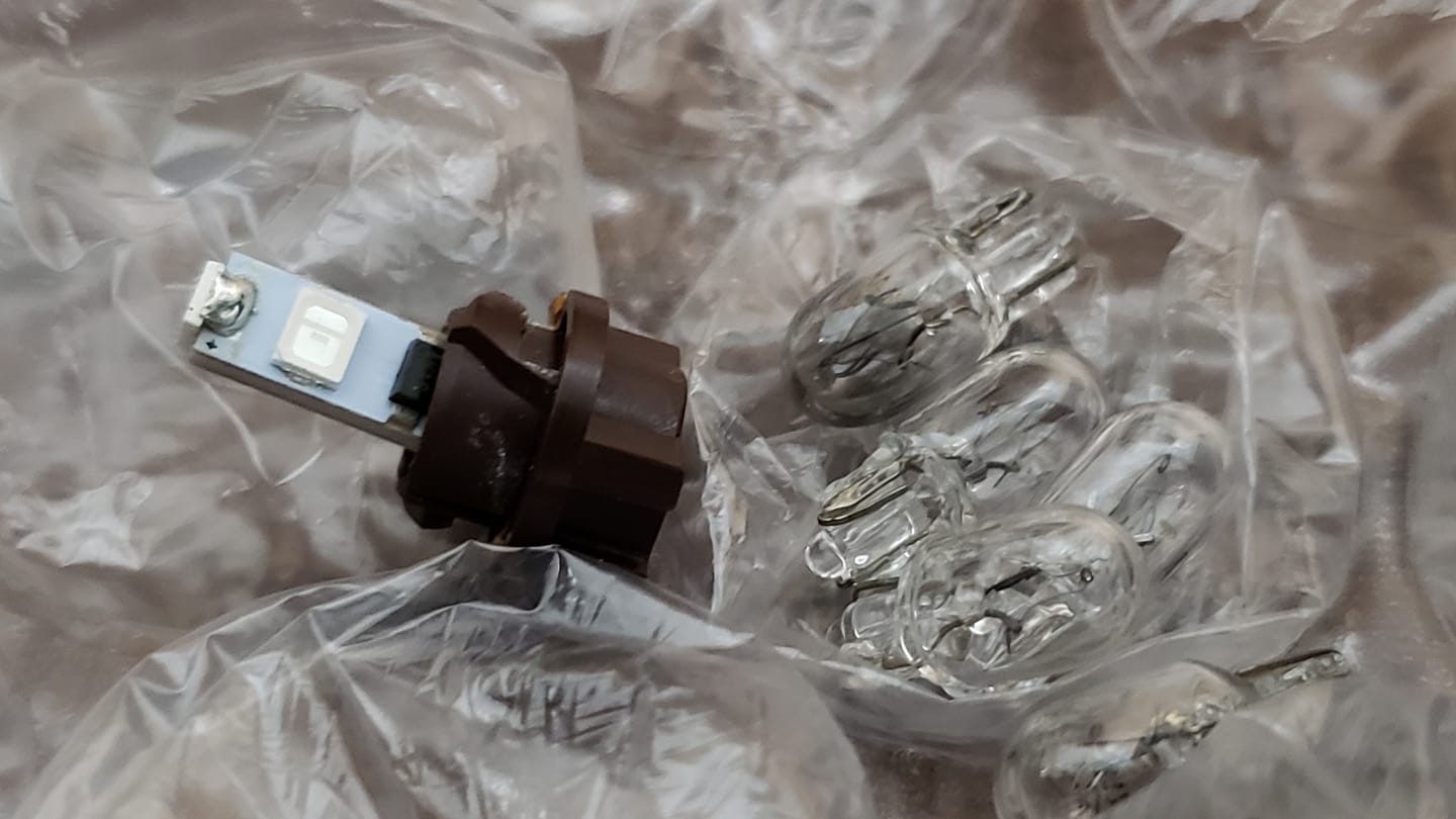


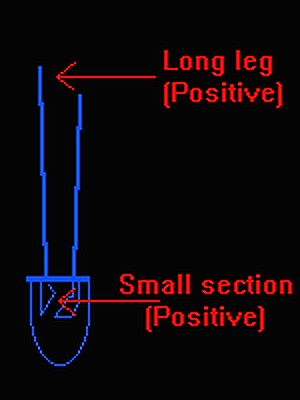
 5mm vs 3mm


")