I am doing a custom dash with a raspberry pi4 and a Onegauge hub. As seen in the pic I will be utilizing the factory temp and fuel gauge to tie in the factory look. You may recall all work I did to get the Bose to control my aftermarket DSP so I can keep the factory look. I think the whole dash look is slick in the 3.0’s (I don’t like the radio appearance in 02/03).It’s a Tenzio HDMI touchscreen.
I will be keeping all the factory dummy lights and adding a neutral indicator. This will also monitor the afr, boost, etc when I get to the supercharger. So I will have to figure out how the ecu sends signal to the dash and which wires are which.
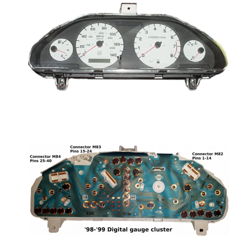
Quick document I wrote up on swapping an analog (’95-’97) to digital (’98, ’99) instrument cluster. The only wiring addition you’ll have to make is constant B+ for the digital trip meter.
I’ve been wanting to install a carputer on my maxima since a very long time, but I never had the experience or the time/patience to install all the equipment. Finally, starting in mid December, I’ve finished installing my carputer.
I tried to make this as factory finish as possible without fiberglassing. Also, I tried my best to keep everything intact and not create unnecessary holes.
I actually never took a picture before I started this project, but here is the closest picture of the stock picture with the original Bose headunit.
Next, are a few computer setup pictures and also my homebrew shutdown/startup controller for the computer. I’ll post those schematics soon.
SPECS:
HP Pavilion DV2020US laptop stripped
MSNTV box
ELMSCAN Compact OBDII Scanner
Garmin USB GPS 20x
Bluetooth Adaptor
Metra Face plate adaptor
40 GB Hard Drive
2 GB Ram
Centrafuse 2.1
GMPC Plugin
This next picture is my homebrew startup/shutdown controller. You can see that I used a computer power supply box to put my controller and extra wires inside. It just so happened that that psu fits perfectly and flush with my headunit. The red and black rca cable are connections that I’ve made on the computer that connects to my power switch and laptop lid switch respectively. More information about this schematic will be posted later.
INSTALLATION PICTURES
Here are a few pictures of the install in my car. I decided to put the computer underneath the driver’s side seat. I also pulled the wires through the channel underneath the seat along with the seat warmer and seat belt wires.
This next picture is my obdii connection to the car ecu, followed by gps installation pictures.
Next, my startup/shutdown controller needed someway to determine if the car is on or off. So, luckily I found a telephone acc line that was not being used in the fuse box.
FINISHING UP INSTALLATION
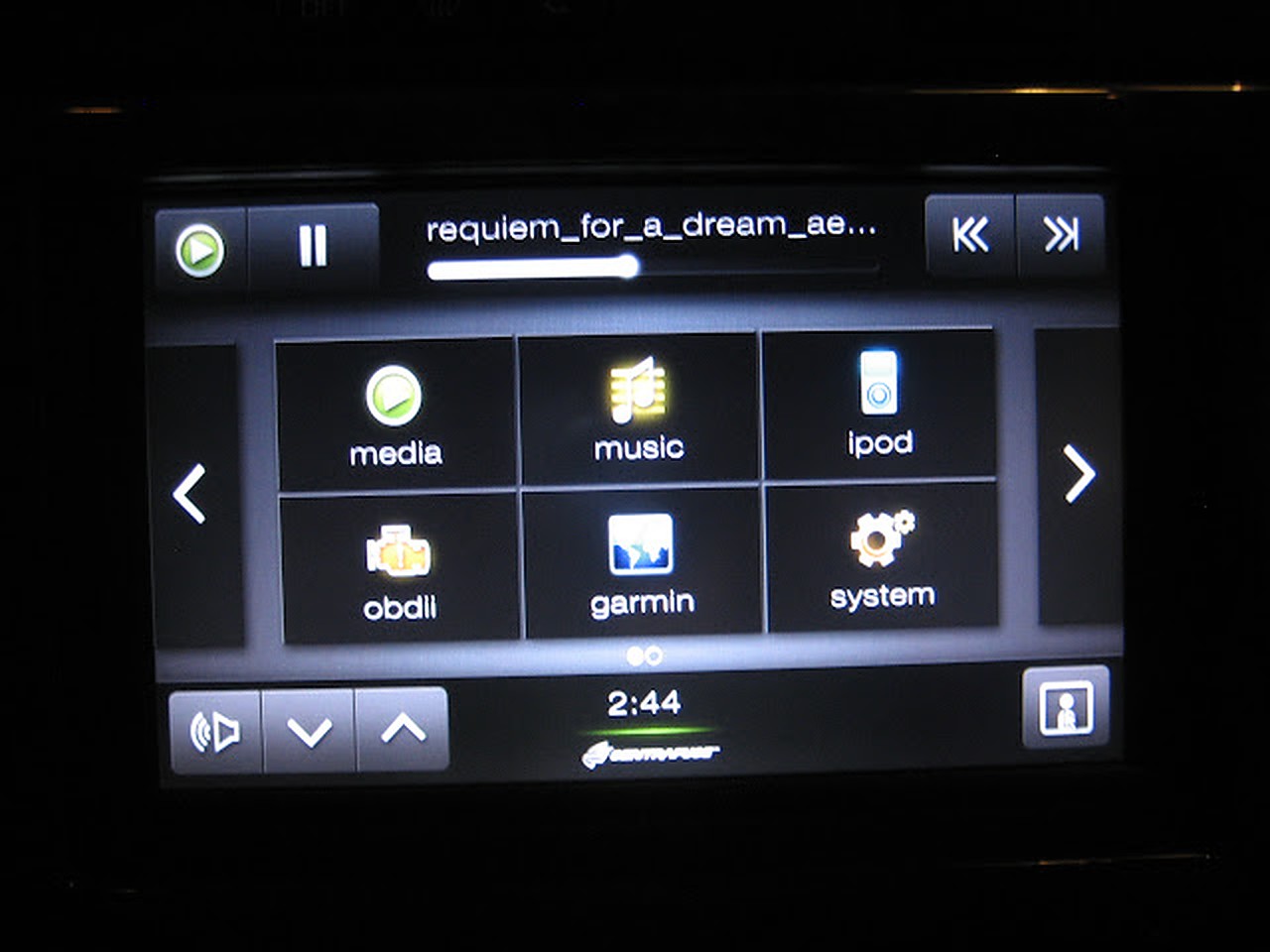
Few Screenshots
CONCLUSION
This project took a while, but I learned that patience is the key. There were a lot of times when I second thought myself if I should continue this project, but I just kept believing in myself. There are still a few small problems that I will fix soon.
PROBLEMS
Need better sound card
New Bluetooth Device
This laptop is actually equipped with a pretty good sound card, but the headphone jack and spdif connection both have a lot of static noise from the hard drive. This is not a grounding issue, but the motherboard fault. I remember when I used to use this laptop, I could hear the static on my headphones as well. I’ll probably just get a new usb soundcard.
Also, the bluetooth device I have is flaky, it works sometimes and sometimes it doesn’t. I’ll prob just get a new one.
Lastly, but none the least, I’m going to continue improving the functionality of my startup/shutdown controller.
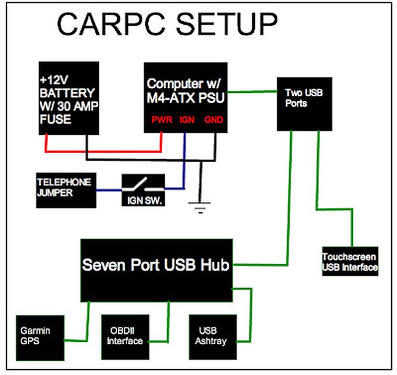
So I got rid of the old setup and had the following new components:
Intel D410PT MINI ITX Motherboard w/ Fanless 1.6 GHZ Intel Atom Processor
Corsair 32GB SSD Drive
TUFF N TINY 4GB Flash Drive
Nlite Windows Xp Professional SP2
Custom Plexiglas enclosure designed to fit completely behind the dashboard
M4-ATX Startup/Shutdown Controller
OEM Nissan Heated Switch integrated for on/off purposes
Custom Integrated USB Port in the Ashtray
I still kept the same devices (like the Garmin GPS, OBDII controller) but I decided to store all my music in a flash drive. Since the software I was using was Centrafuse 3.1, it still did not support ipod capibility with iphones and itouches, I decided that there is no point in storing the music on an ipod.
The old setup
So, now the new stuff, the goal of this project was to:
Keep the existing OEM look
Fix all problems from previous setup
Integrate everything behind the dash
Keep the new project on a budget.
Next, I wired my OEM Nissan Heated seat warmer switch. I wired it up for use and then used a 2000 grit wet and dry sandpaper to remove the marking off the switch.
Next, I made my wiring diagram which is shown below.
Installation
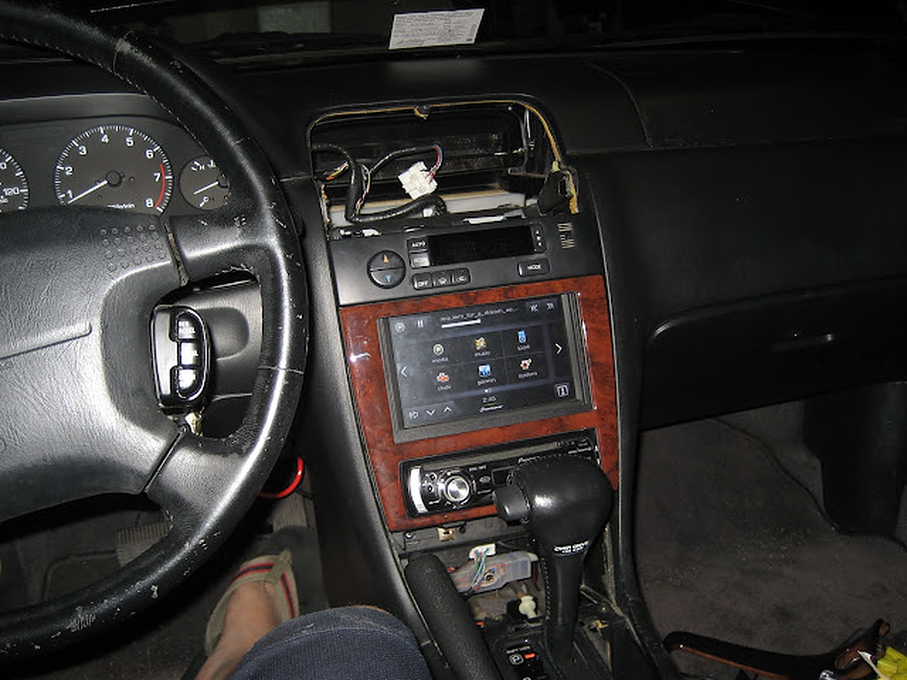
Here are some install pictures. Below you will see my plexiglass enclosure. The design came out perfect, I had only a few mm in tolerance around the edges. I also fitted a small fan to blow any heat generated.
Now doing a test run.
Here is the finished setup with everything working, as you can see the new switch at its location.
For anyone who needs an English reference for the AC Controls, under dash and engine fuse box of the Y33 Cedric/Gloria. Here is a photo of mine from a Middle eastern spec LHD Y33 Gloria. Hope it helps.
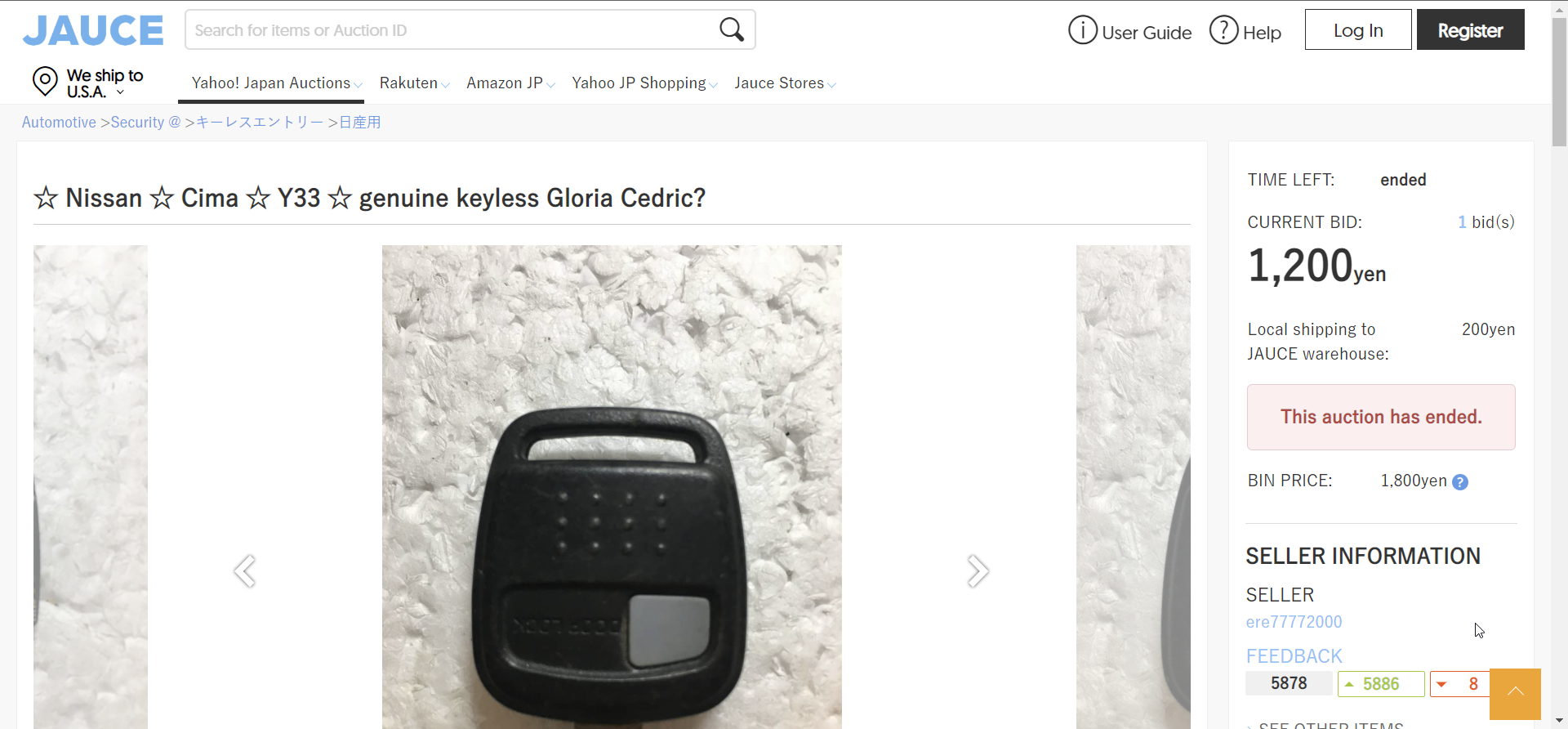
For those that have a y33 Cima and your key is the keyless remote as well, I finally got mine to work. My car came with a bad transmitter key. I ordered a used key from Jauce auctions and then swapped the transmitter over to my key. I tried and tried to program the keyless portion like owners of most Nissans in the USA but I could never get into the programming mode.
On the JDM version, the programming mode begins when the doors unlock, the hazards never flash like the US models. I have attached a screen shot of the programming instructions I followed and it worked first time. Unfortunately, the separate fob did not work.
About one year ago (2000), I was driving back from work, and I saw a single streamer of smoke coming up from my steering column. I immediately tried all the switches on the steering column, thinking that I will find out which switch has gone bad, and maybe I will make it stop.
Well, everything worked just fine, and the smoke did stop. A month later the same thing happened, a single streamer of smoke.
After the first time I parked my car in the garage thinking “I hope that I don’t set my garage on fire if she lights up.” It never happened again.
In August 2000, when I signaled to turn left, after the turn was completed the signal would cancel, but the turn signal relay would click about twice the usual speed, “click-click-click-click-click” Luckily for me the turn signal light did not flash, it was just the relay.
I removed the relay, and opened it up. It is not your typical relay. It is a relay with printed circuit board on the side. I noticed that the circuit board was cracked, and it looked like a few traces may not be in full contact. I added a little bit of solder, thinking that it was now fixed. I was wrong.
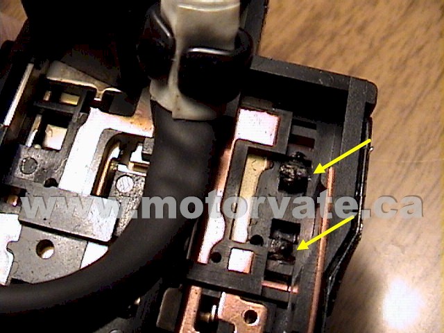
Now it is March 2001, and I noticed that my turn signal was not “smooth” like I remembered it. It was very notchy. I removed it from the steering column, and saw this:
The YELLOW ARROWS point to some melted plastic. The RED ARROWS point to what the contacts should look like. The yellow arrows in the right picture above, show little plastic “parking” islands are melted. This made the contacts sit lower, and they were only touching a little, causing a little current to flow through the relay. The relay senses current, via the built in IC, and makes the relay pulse, but because the current is very small, it flashes faster. (just like when you have a burned out turn signal bulb, the flasher goes faster)
Anyways, this is where the smoke came from. YEA! I found it. My car is not going to burn down!
I tried to “file & fix” the contacts, but it did not work.
I called up North End Nissan, and 1 day and $71 later I had my turn signal back to where it was, nice and smooth, with no harsh clicks.
Problem solved in 10 minutes, but it took over a year to figure it out.


 to Digital (1998-1999) Instrument Odometer Cluster")


")


")


 Fuse Box References in English")


")