The first mod I ever did to my car was the cruise control always ready one. I use it every day, 10 times a day, and I love it cause I’m lazy. I don’t have to turn that annoying rocker switch and then push set, I can just push set.
I remember when I did it a couple of years ago the current sticky did not apply to the 99se, its box of relays was different, so I experimented and found the one that worked. I took pictures then, and it wasn’t until I discovered those pictures randomly looking through my computer did I remember I was gonna make my own very first DIY. So here it is:
You need: 5 minutes, (2) 1-2″ strand of wire, 4 crimp-on spade connectors, something to crimp ends, a flat head screwdriver
1. Locate the box that has the cruise control relay in it. I used a flat head screwdriver to pop it open
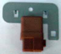
2. Use that screwdriver to pop off the cruise control relay, (this is a picture of the final product), it is the one where you can see two little wires
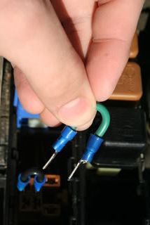
3. Crimp the 2 spade connectors to each end of your little wires, should look like this
4. Plug them accordingly and you’re done!!
Additional Notes:
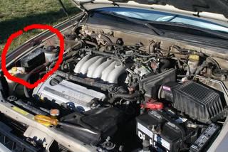
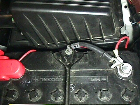
That “trick” as ejarmol described it is only for the 99 model. Nissan changed the electrical wiring. On the 95 through 98 models, the ASCD Hold relay (that’s what Nissan calls it) is in front of the battery.
Look at the cover over the relays that are in front of the battery and you will see one is labeled ASCD. This is the relay that gets removed. If your car has an automatic transmission, you need 2 jumper wires. If your car has manual trans, you only need 1 wire.
The electrical schematics for the 99 Maxima and the 99 I30 are the same, same wire colors and all.
The one thing that was not pointed out is that he has an automatic transmission. There is a difference between the auto and manual trans in how you would do this mod.
If the car has an auto trans, you use 2 jumpers as shown. If you have a manual trans, you use only one jumper. This is because the relays are different for the different transmissions. The auto trans uses a 2 circuit relay with 6 connections where the manual trans uses a single circuit relay with 4 connections.
If you have a manual trans car and use 2 jumpers, you will be shorting out fuse # 12 which is for the ASCD and a few other things.
Issues: My power sunroof switch stopped working this weekend on my ’03 Maxima GLE. I pull it backwards for the sunroof to slide back and nothing happens?
Solution:
This happens to me almost every time I disconnect my battery terminal. I found that this will usually fix it: Use the sunroof tilt switch to open it all the way (you will have to push it a bunch of times), and then do the same thing to close it all the way. Once you open it and close it all the way using the switch, then try using the slider switch thing, and it should open. If it doesn’t, turn your car off and back on and try again. This works almost every time for me.
You shouldn’t have to open it all the way. Just close it and hold the tilt switch (close) until you hear a click…that will reset the switches.
How to Fix/Reset Sunroof motor:
Close your sunroof all the way.
Turn off your car.
Disconnect your battery.
Turn on your lights, and step on your brakes. Do it like 10 times. (You are basically draining the system.)
Installation was actually rather simple but did require some fabrication to get everything hooked up and working. Only a short piece of 3/4″ by 1/8″ steel and some aluminum angle were needed for mounting everything. However, understand that horn kits don’t ship with wiring or connectors, so plan on making several trips to the Radio Shack to get what you need. I suggest 10 or 12 gauge wire (with an inline 20 amp fuse) for the compressor circuit, while any 14-16 gauge wire will handle the switching tasks. You’ll need to tap into the stock horn wiring for the switching.
I am going to try and explain the wiring.
The compressor has two connections. One female end on the compressor and the other end to relay #30. WIRE: female connectors at both ends.
The other compressor connection is ground (negative…frame of the car or run an open connector to the car batteries negative terminal). WIRE: female one end and open or circle connector on the other side.
Relay #85 to ground (negative…frame or negative battery terminal) WIRE: Female connector on one end and open or circle connector on the other side.
Relay #86 gets a female connector and the other end is a male that plugs into the stock horn connector. The stock horn is in front of the radiator (looks like a 3″ diameter disk).
Relay #87 gets a female connector for the relay and the other end goes to the positive battery terminal( open loop connector. Take off the nut on the battery and put the connector between it).
Relay numbers:
85: Ground
86: Stock horn switching
87: Hot lead that runs to the battery terminal (POSITIVE).
30: Hot lead running to the compressor.
Short cut for Maximas:
The relay is not necessary for the air horns to work.
Plug a male connector into the stock horn switching, plug the other end of the stock horn switching into the bottom of the compressor (positive)
The compressor has one more connection (negative), the negative to the compressor and the other end to the ground (car frame)
This picture is taken to show where the horns are installed. We’re looking down on top of the driver’s side headlight, and you can see the front of the horns light up by a drop light in the space in front of the wheel inside the fender.
Here is the wiring that goes to the battery. Since the battery was so close, we didn’t bother wiring to a ground bolt. We used 12 gauge wire.
The horns are mounted inside the drivers side front fender, behind the fog light. Here is a picture showing the horns mounted to the strip of metal. We picked up the metal at Home Depot, they’ve got tons of it. Doesn’t have to be 3/4″ x 1/8″, anything in that range will do. Underneath the metal, you can see the support bracket that connects to the fender. This comes with the Maxima. It is too thin and also has a shape to it that wouldn’t allow mounting the horns to it.
You can also see the relay is attached using the same bolt as the horn all the way to the right. The top and bottom terminals connect to the compressor, thus the heavy 12 gauge wiring. The other wires tap into the stock horn wiring to control the relay, and don’t have to be heavy duty, so I used some extra speaker wire I had laying around.
You are looking top down…between the radiator and the front grille. The picture shows the stock horn switch (black) and the wire used to tap into the stock horn. By tapping into the stock horn for switching when your factory alarm goes off it uses the air horns. Also disconnect the other stock horn that is in the engine bay on the left side.
Here’s another view of the above picture, taken from farther out. You can easily see the fender support brace here. Take the 10mm bolt out, then put the horn bracket between the support brace and the frame. This is also where I ran the ground for the stock horn.
Here is another view of how we mounted the horns.
Yet another angle. These pictures should be clear enough so that you can understand how to do this on your own.
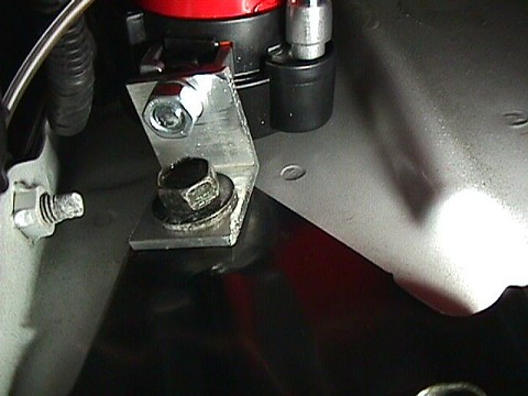
This picture is taken from the floor, looking up to see where the compressor is mounted. We used a short section of 1 1/4″ x 1 1/4″ aluminum angle to mount the compressor to the top of the shipping tie down hooks which are attached to the frame via three heavy bolts.
Here is a close-up of the aluminum angle we used to mount the compressor. Again, this was obtained from Home Depot, but be warned… the shortest length they sell is 8 feet… and you only need about an inch or so to make this bracket. If you felt adventurous, you could make the bracket by bending a piece of the same 3/4″ x 1/8″ steel that the horns mounted to.
Finally, here is a good shot of the area where the compressor mounts. The horns are at the top of the picture, the compressor mount is below the rightmost horn, and the driver’s side fog light is at the bottom of the picture.
Basically this is a mod that short-circuits the Cruise control relay that requires you to turn on the toggle switch on your dash to the left of the steering column…
What you’ll need:
1. A couple of inches of 14-gauge wire (16 or 18 might work, but I didn’t want to risk the wire melting)
2. A couple of crimp-on flat spade connectors
What to do:
Attach the spade connectors to either end of your wire, like this:
Open up the relay box on the passenger side of the engine bay, you’re looking for the slot that has ASCD (Automatic Speed Control (Device):
Remove the ASCD relay from its slot (a small flat-head screwdriver will help you with the clip that holds it in). Now insert your wire into the connection that is perpendicular to the other 3, and the connection opposite that, like this:
Put the cover back on the relay box and put your unused relay away, cuz you’re done. Now the cruise control will be on whenever the car is on.
Make your 4th gen Maxima beep when the alarm is turned on for less than $10. If you don’t like to watch the alarm turn on but would rather hear it turn on then this mod is for you.
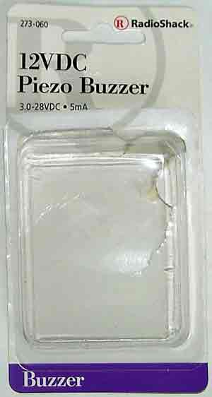
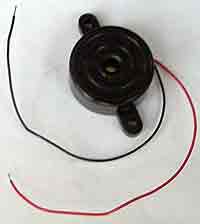
Basically, there’s relay (multi-remote control relay) in the trunk which flashes the corner lights when the alarm is turned on. We’re going to buy a cheap $3 buzzer, another $4 relay, and attach it to this MCR relay so that the car beeps. Hear it for yourself: buzzer.wav
The mod should take less than 1 hour to perform. Here’s the schematic:
1. Go to Radio Shack and buy item # 273-060 (buzzer) and item # 275-248A (mini-relay).
2. Remove the Lamp and BCM fuses before starting work. The Lamp fuse is located inside the car. The BCM fuse is located in the engine bay.
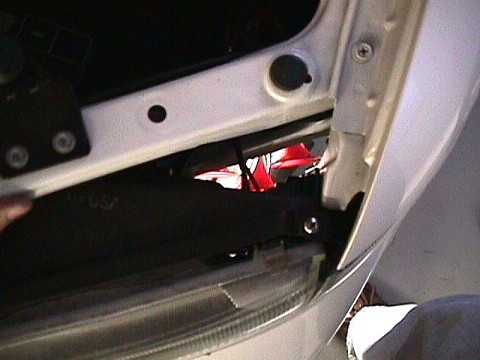
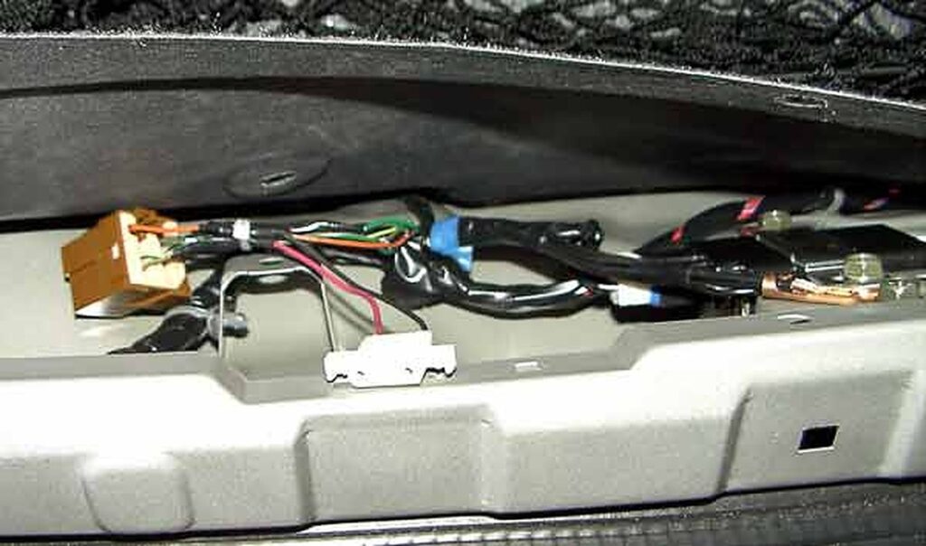
3. Locate the Multi-Remote Control Relay in the trunk. Start by removing the plastic cover above the trunk latch. The relay is the brown rectangle in the picture below:
4. Remove the MCR relay and it’s mounting bracket. There’s a mounting tab for another relay so I used this space to mount the new relay and buzzer. I also used connectors to make the mod removable (although this could move the budget into the $10-$15 range).
5. Splice into the “Green/Orange” wire (orange is the strip color) for power (+12v). There’s 3 of these wires so just choose one. Next, splice into the orange wire (solid color) for the sink from the BCM (ground).
6. Connect and test (refer to the schematic for details). The final setup looks like the picture below. Turn on the alarm and it should beep twice. Note: don’t splice your buzzer into the G/B or G/Y wires (to save on the extra relay) unless you want to beep while turning…
I have a 2009 Maxima SV with both electric tilt and telescoping functions. I am at 92k miles and recently my tilt motor stopped adjusting the steering wheel, I know, first-world problems here. I know the motor still worked because you can hear it moving what’s left of the gear.
I did some research and yes, you can buy a new motor from Nissan for $200. However, in my research, I ran into this product – Dorman 905-522. At this point in time, it’s a poorly made product and badly advertised as well. Nowhere, does it say that it’s compatible with 09 Maxima, though later Maxima’s are on the compatibility list. I saw a single review of this product on amazon and decided to take a plunge.
Yesterday, I had the “pleasure” of repairing my motor. So the product comes with new shafts and molded on Nylon gears as well as C-clips and some grease. It also comes with pretty good instructions on the actual repair.
Once you have the motor out, you follow a couple of steps from Dorman’s manual, specifically:
Take off the c-clip or locking the o-washer from the end of the shaft.
Remove a set screw/spring from the adjustment block (located on the side of the block, inner hex)
Unscrew adjustment block
Use the permanent marker to draw a line across the outer nut, inner locking nut, and body of the motor. This is necessary to apply the same preload to the inner bearings
Remove the large hex nut with a crescent wrench, it was not super tight. I used adjustable pliers to get it off.
Then slide the black spacer block included in the Dorman kit over the shaft, it should engage the inner nut. The block is square, but the nut has 12 points, so it will engage without any issues.
Spin the inner nut off
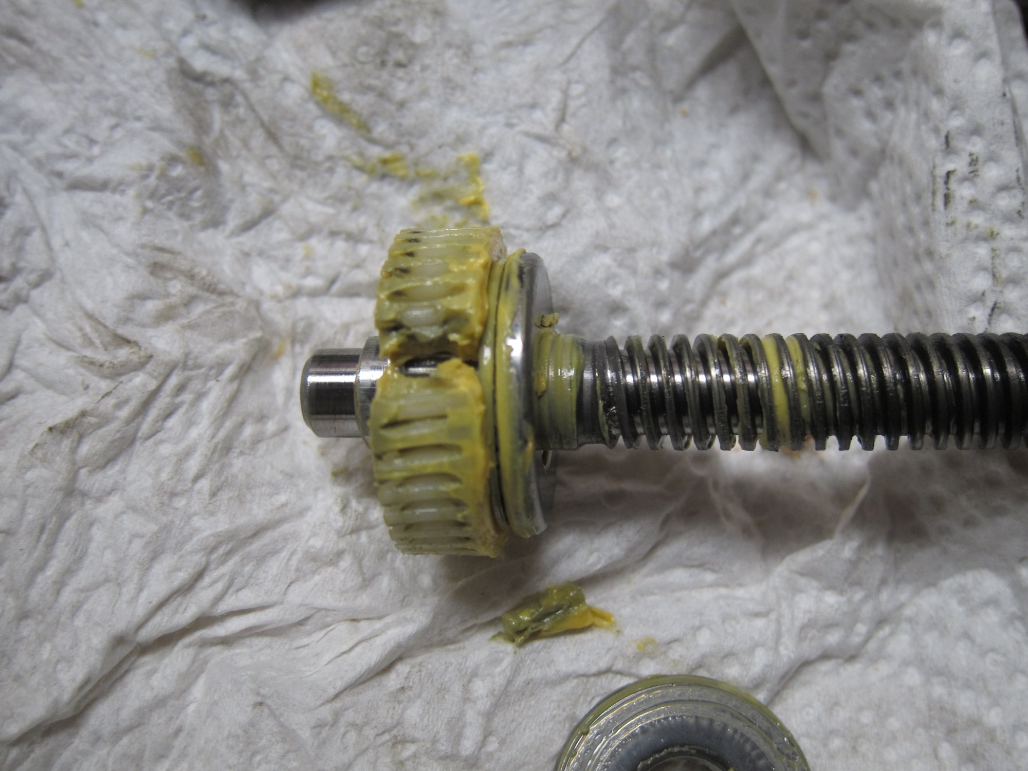
Remove old shaft, be careful, there is a bearing on the bottom and the top of the nylon gear.
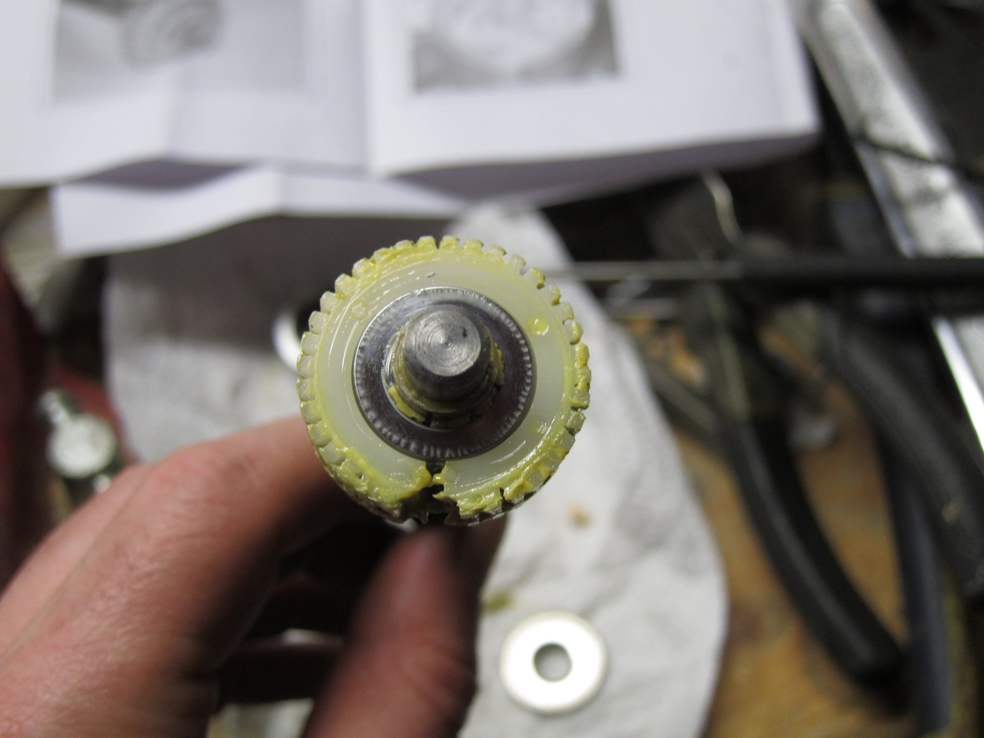
At this point you should confirm that your old nylon gear is busted, mine had a whole chunk of gear missing. Assembly is reverse of disassembly.
But here is some bad news and good news.
Bad news first: When I tried to spin the adjustment block on the new shaft, the block was getting bound up in many spots, so there are problems with threads on these replacement parts. Since I have gone so far with the repair, I did not want to put the old broken part back in. What I did is used small files to file down the metal threads on the new shaft. I basically put some taper on the shaft threads and after about 2.5 hours of manual labor, the adjustment block would thread on smoothly without any issues.
Of course, it’s completely asinine to expect a person to file down metal threads to get the part to work. So here comes some mixed news that hopefully will turn into good news soon. This morning I contacted Dorman about my experience and they told me that they know of this issue and the product is supposed to have been put on hold with no further sales taking place until they retool and fix the issue. They were not able to tell me when the new product will be available, but hopefully soon. I left a 3-star review for this product on Amazon, and hopefully, when Dorman gets a new design done I will be able to update it to a 5-star review.
The good news is that there is no need to purchase $200+ new motors and throw out a perfectly good motor with broken plastic gear. The Dorman kit cost me $35 shipped from RockAuto, the kit includes both tilt and telescoping motor shafts. The R&R of the motor, given a proper shaft, is no more than 30 mins and that is taking things apart slowly. I can do it in 5mins now. For crafty guys, the threads on these shafts are M10 x 2.0. I don’t have a die or thread chaser this size, as a matter of fact, it’s a very oddball size that’s not easily gotten.
I do have some pics, but frankly, between the TSB and Dorman manual, you should have no issues taking things out and putting it all together.
Old nylon gear broke, chunk of it is missing
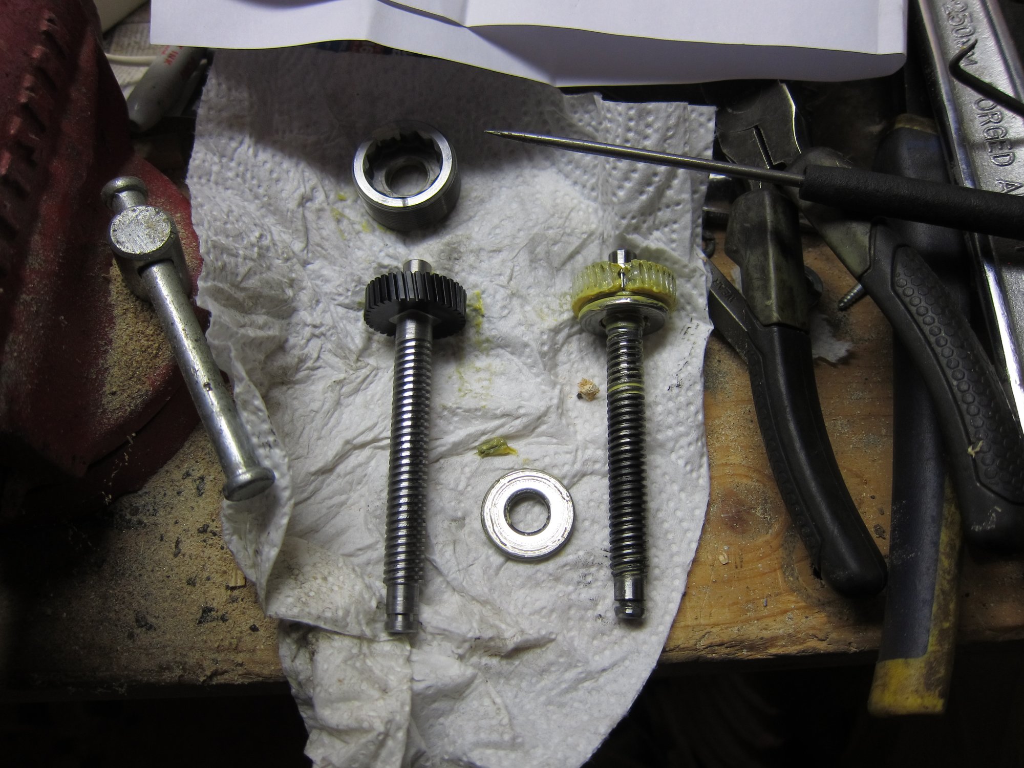
New Dorman gear side by side with old one
Old gear, notice that the shaft threads have a small taper to them. The gear also still has the bearing (shiny silver disk) still on it.
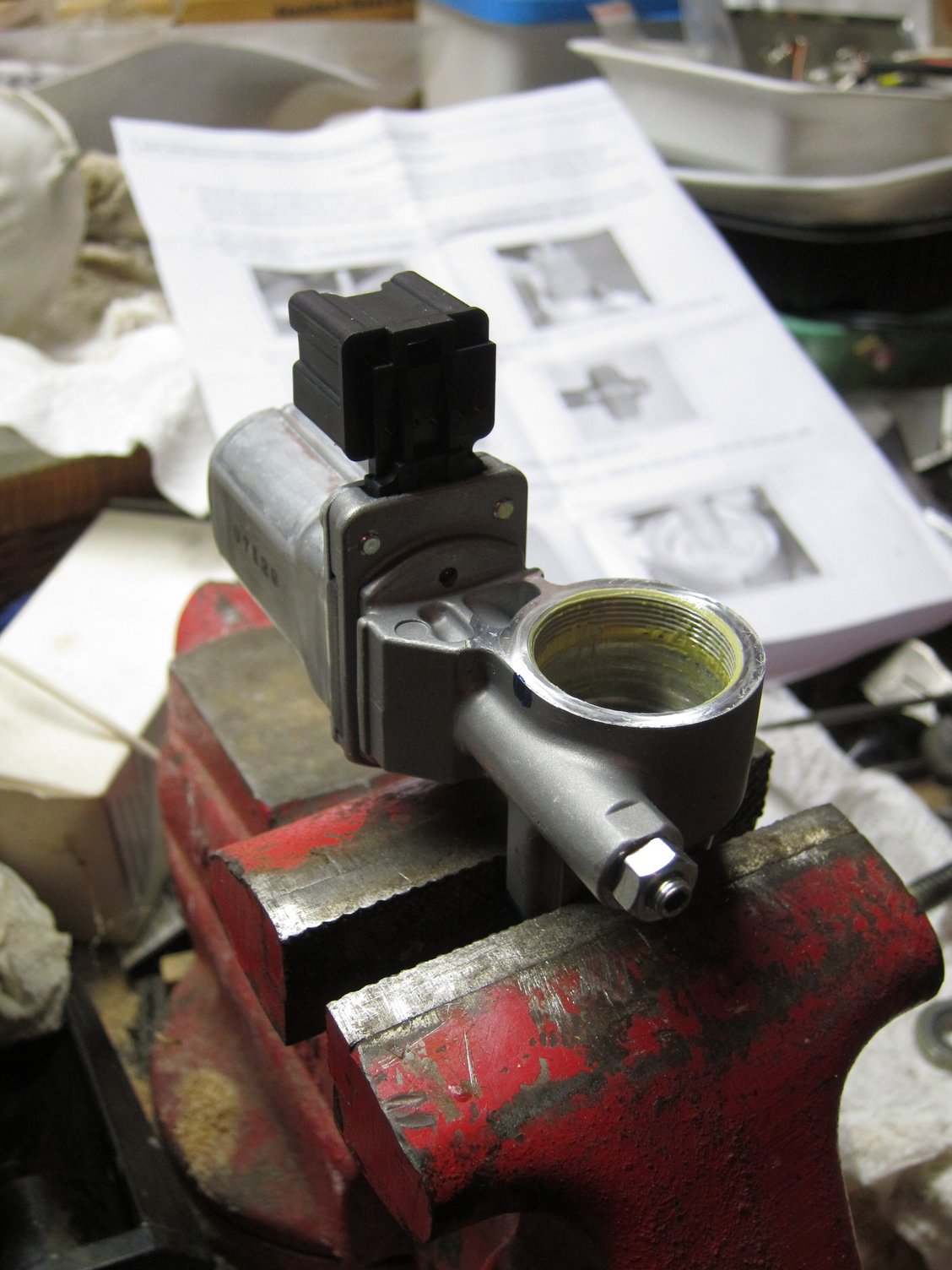
Tilt motor completely disassembled in the wise.
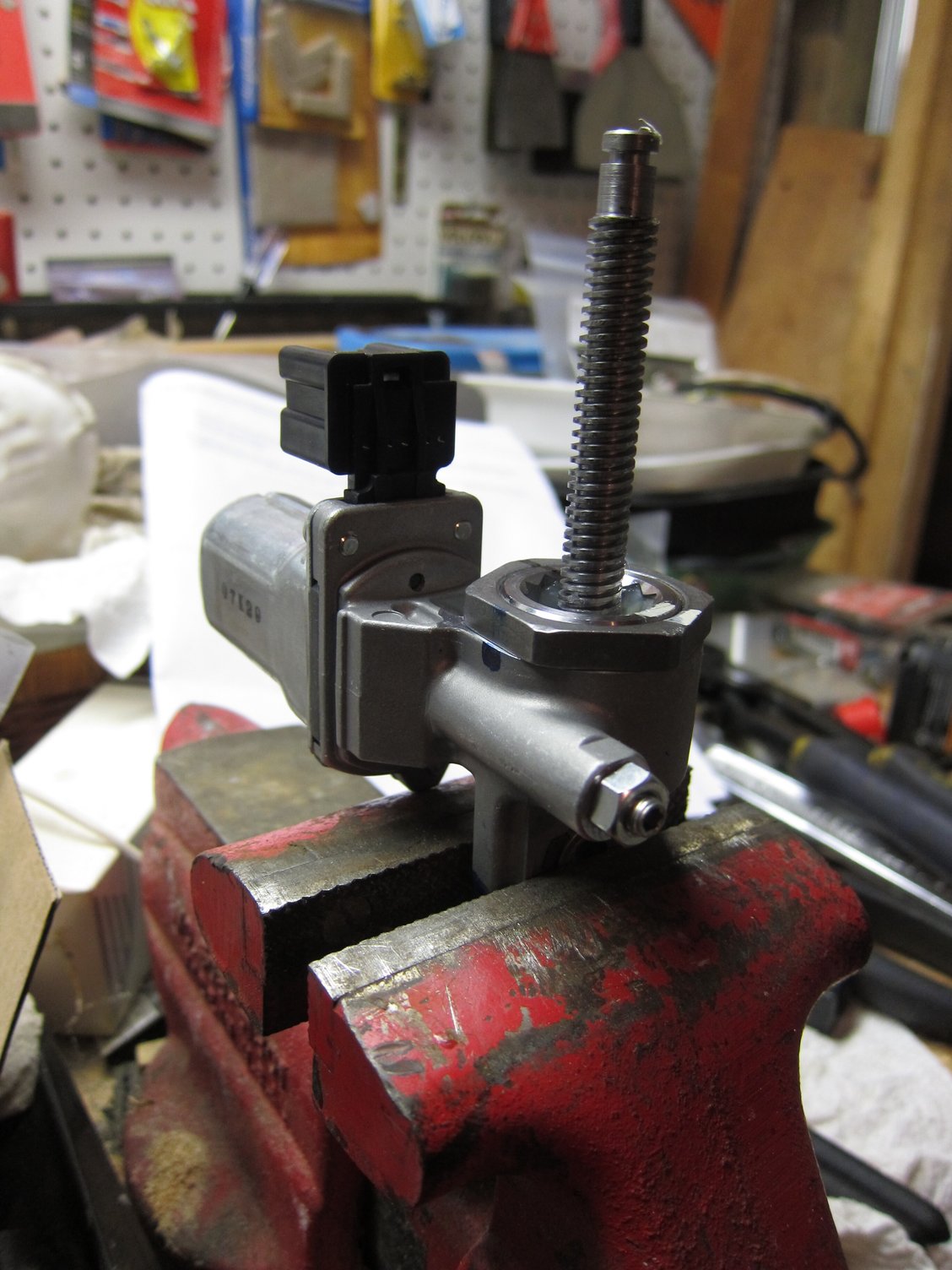
Tilt motor reassembled with new shaft.
Update
A follow-up on my repair. Sometime last fall I had an issue with my repaired tilt motor. One morning it just gave out, but the next day resumed its function. I opted to simply adjust the steering wheel and turn off the easy-entry function.
I was not sure what was wrong with the motor and thought that perhaps the motor itself is giving out. The telescoping motor died sometime earlier, don’t recall when exactly. After the initial repair in 2015, I did receive an “updated” part from Dorman in 2016. That kit was on the shelf until yesterday.
Since I got time on my hands, I decided to fix both motors. Followed my own links to get the motors out, but ran into an issue with removing the telescoping motor out. Mine died in a position that was very close to the dash, preventing easy motor removal.
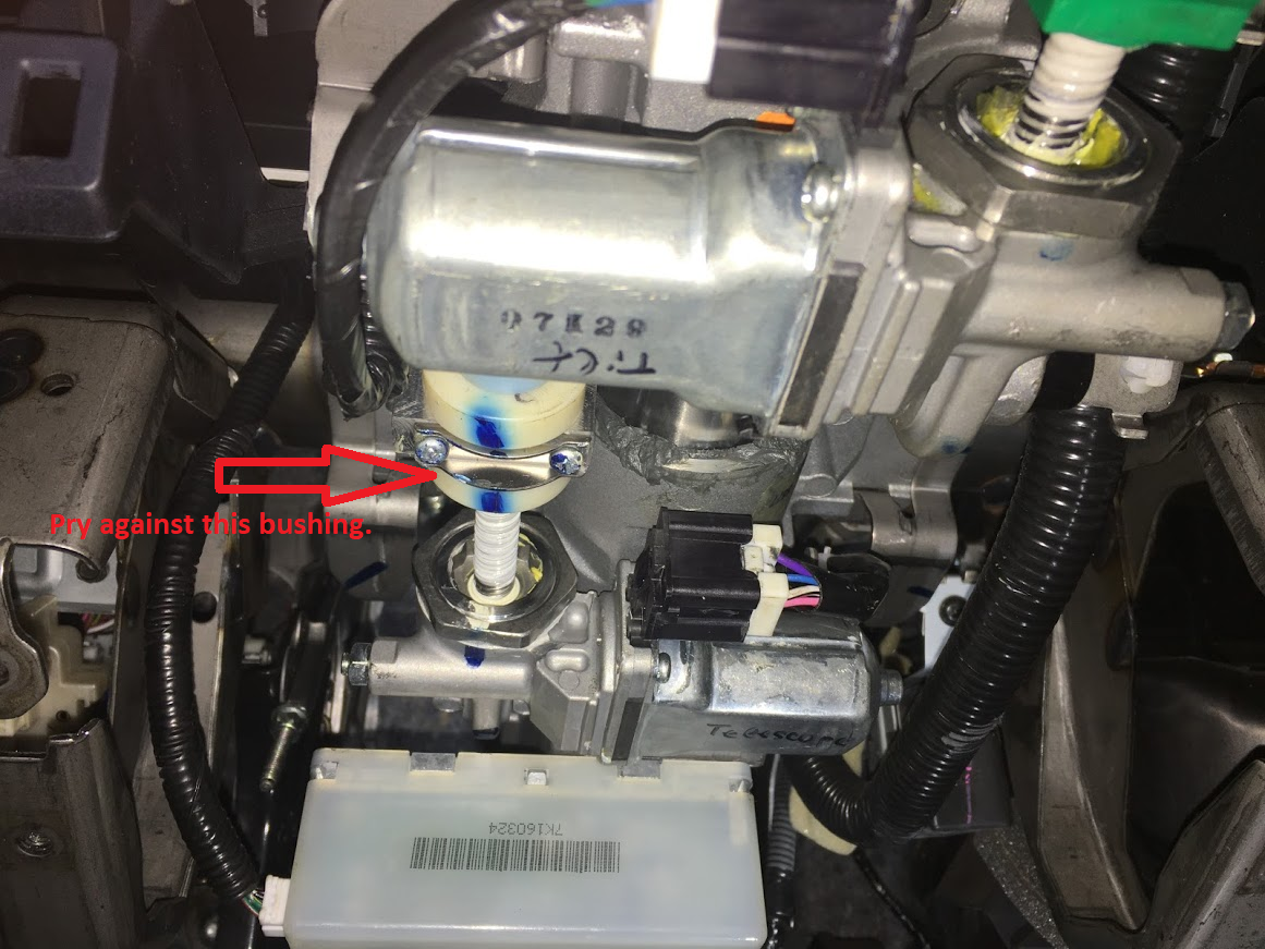
The procedure explains that you want to pull on the steering wheel while actuating the motor to completely telescope/retract it out. I was not successful in that procedure. What I did instead was used a prybar between the white bushing and the rest of the steering column. It did not require much effort and applying prybar pressure while actuating the motor accomplished the task. Note that the motor had to be bolted in while performing the task.
On the positive side, I had no issues whatsoever with redesigned Dorman parts this time around. Both shafts were a perfect match for factory threads and no time had to be wasted to file anything down. I can wholeheartedly recommend the Dorman kit vs buying new factory motors or even salvage ones. Again, the most important part is to mark the relative position of how parts are put together prior to disassembly. After replacing the shafts, just realign things to the marks that you made and preloads will be perfect.
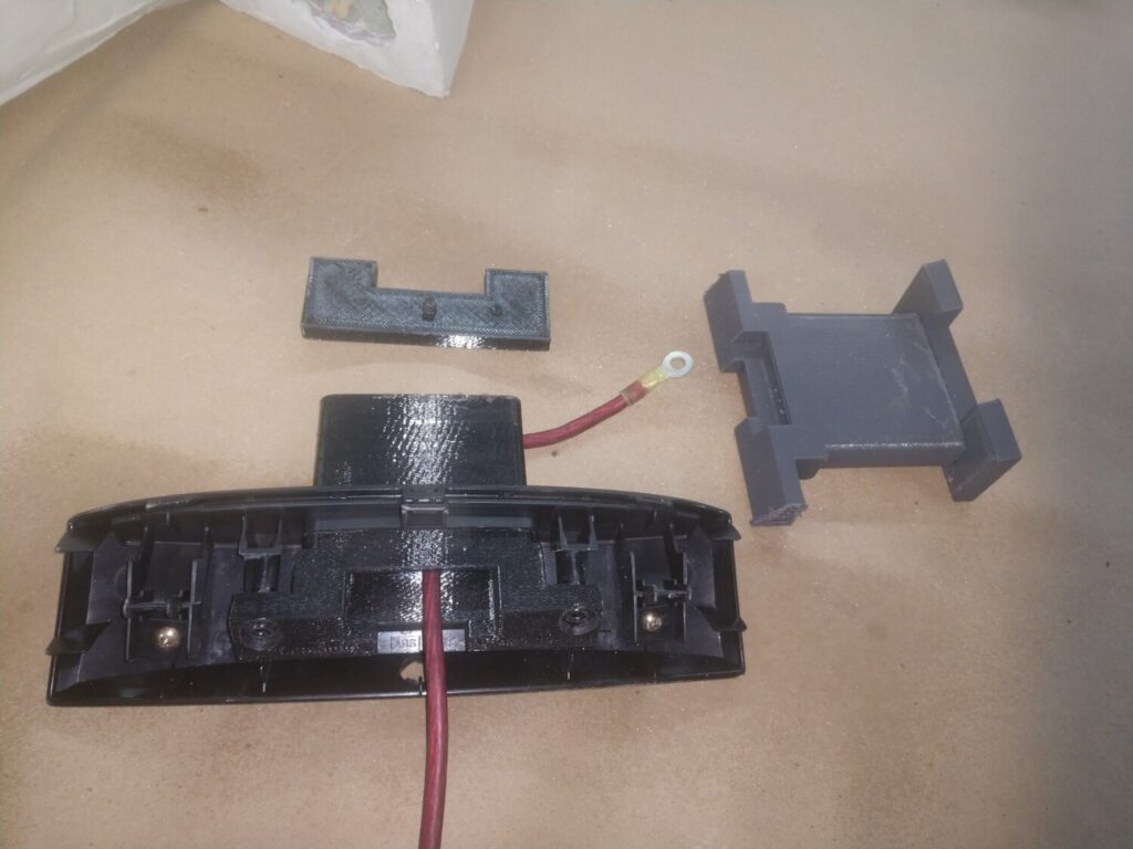
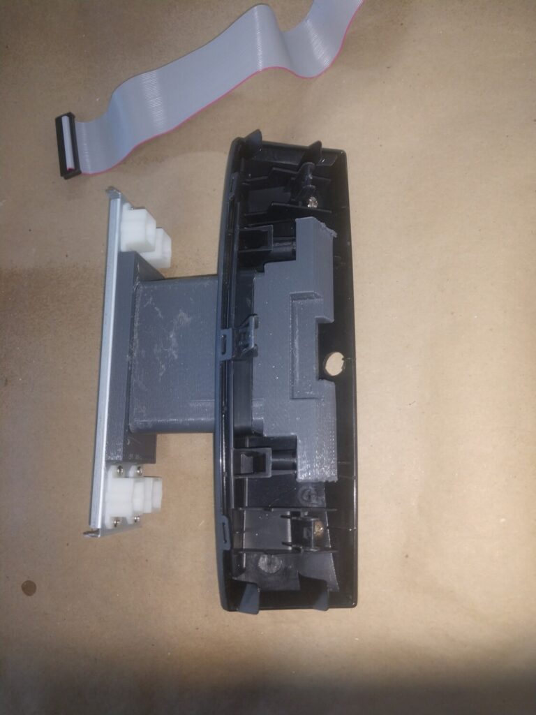
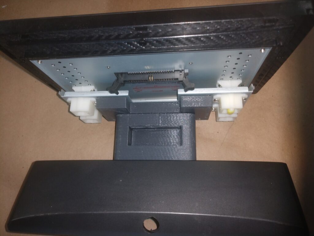
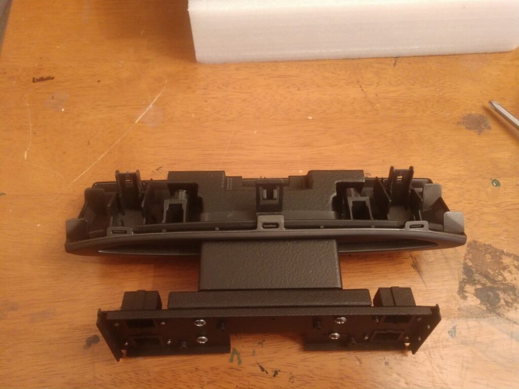
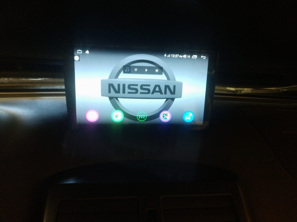
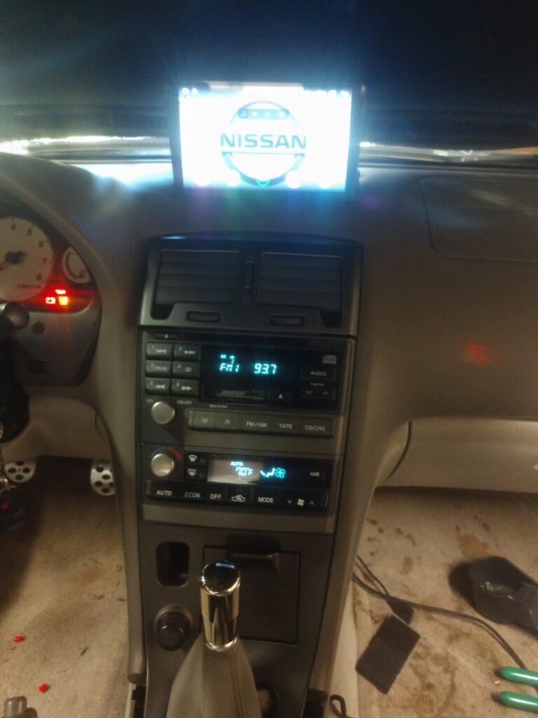
It has a USB input, A2DP BT (via interface), controls my DSP as well. The screen unit’s output can go through the Bose or straight to the DSP via optical cable. My end goal is to get Windows programs running on it. Think Datascan and Minidsp software.
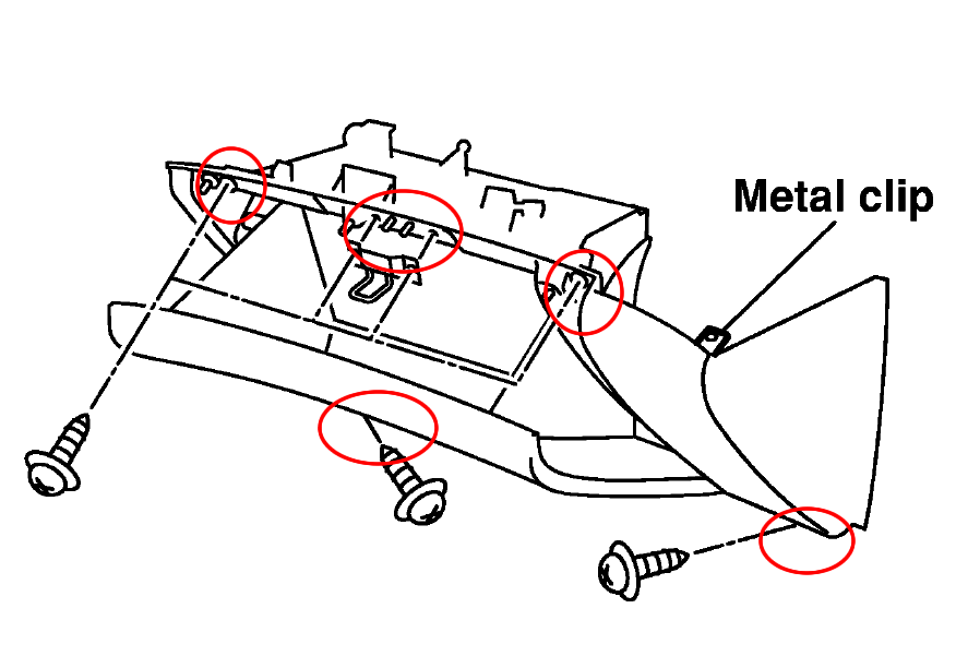
2. Remove the 4 screws holding the the glove box, two at the top and two at the bottom
3. Once the screws are removed pull out the glove box. You may need to use a crew driver to undo the right/top clip.
4. With the glove box removed, you will be able to see the “Fan Control Amplifier” for automatic air condition system or “Blower Motor Resistor” for the manual system.
5. Remove the 2 screws holding the Amplifier/Resistor, pull out the Amplifier/Resistor and install the new one.
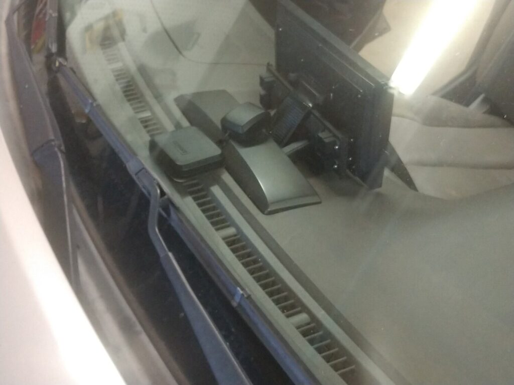
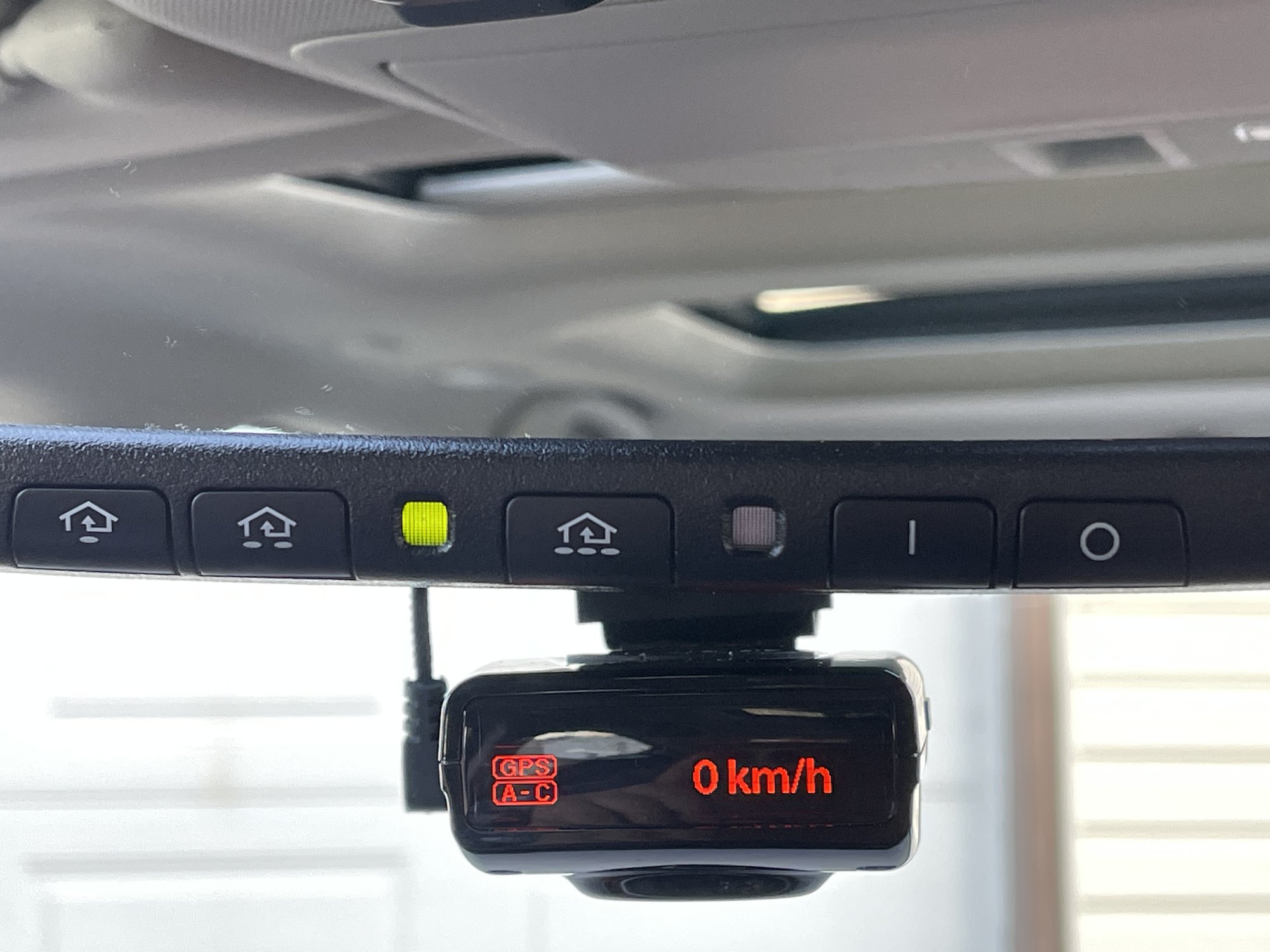
Just finished hardwiring Radenso pro-M with Blendmount and Mirrortap to my 2020 Maxima Platinum over the weekend. This is for rearview mirror with Auto Dimming and Homelink.
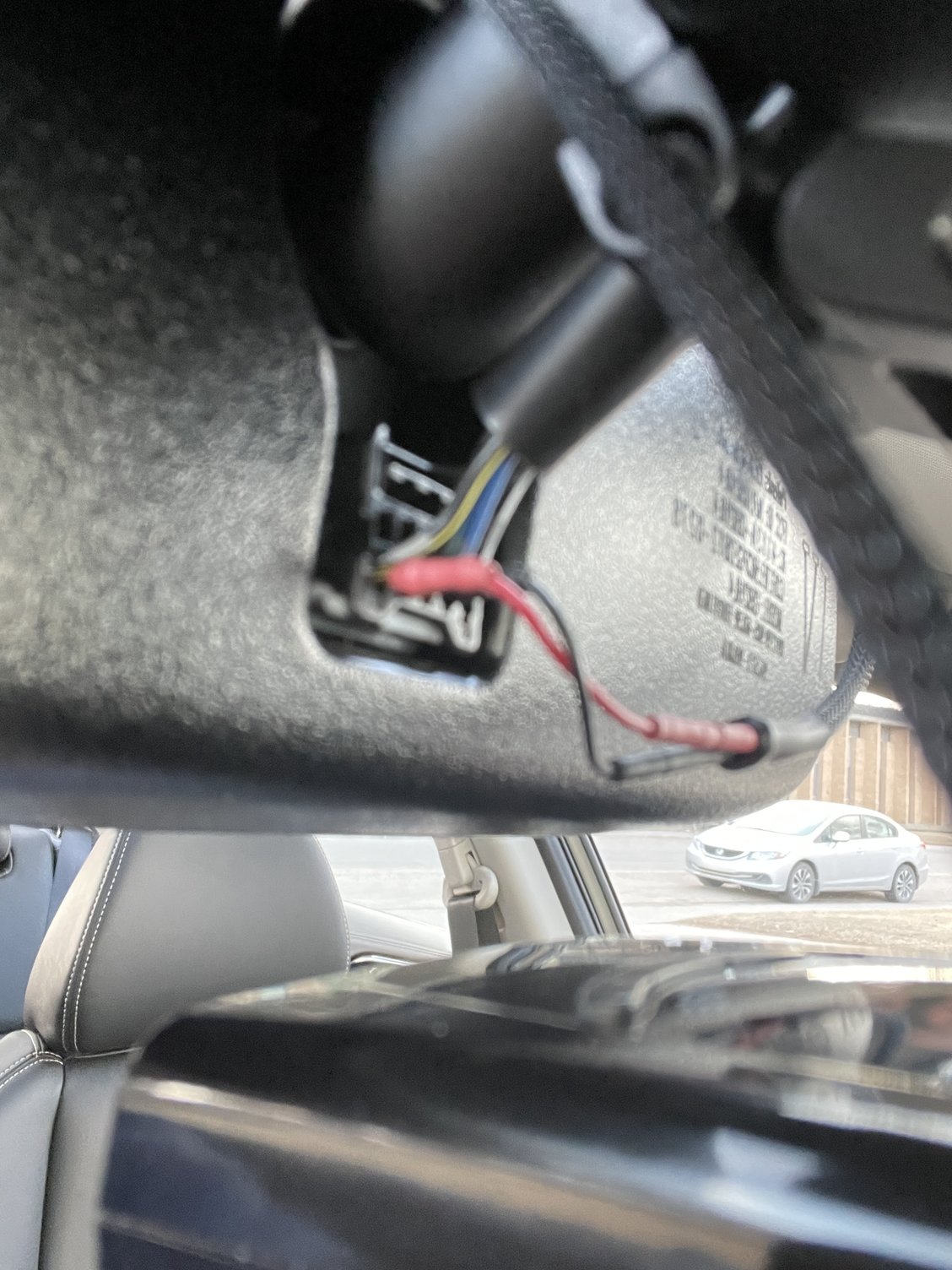
White/Black wire is + constant 12V (near driver side)and the “third” wire Black is – Ground.
Yellow/Black wire is + for ACC 12V. (passenger side)
Pricing is for March 2021
Mirrortap MTX-2015 US $59.52 (blendmount.com)
Radar detector used is Radenso Pro-M CAD$680.38(Bestbuy.ca)
Mount is BlendMount BRD-200R CAD$159.56 (Amazon.com)
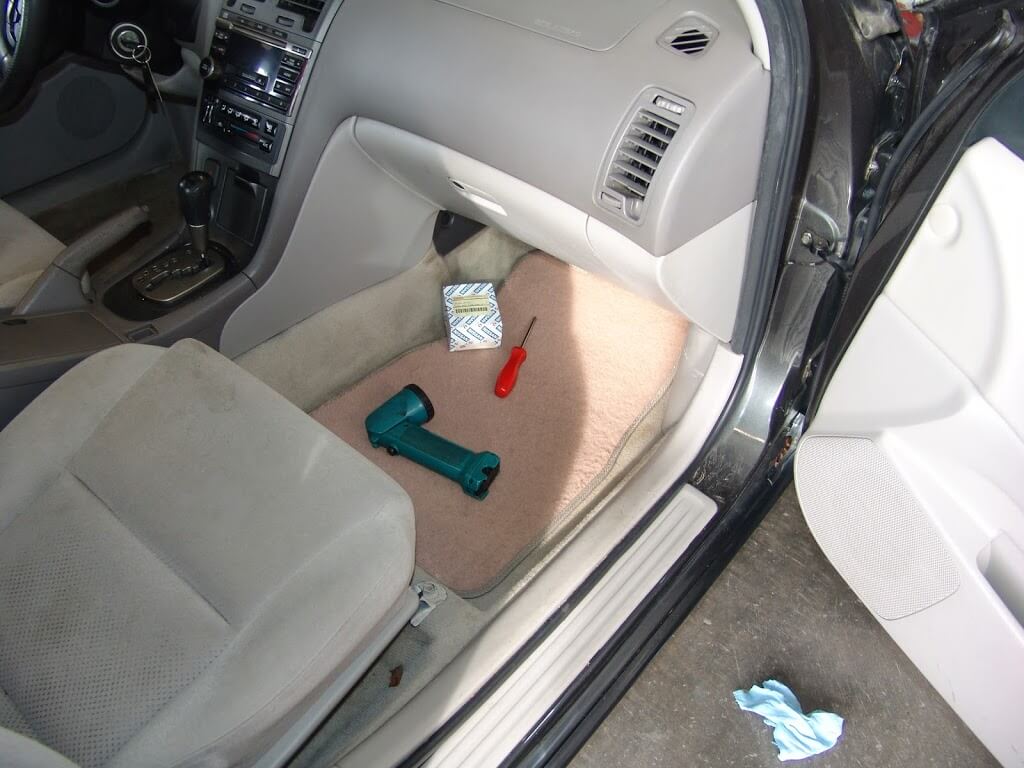
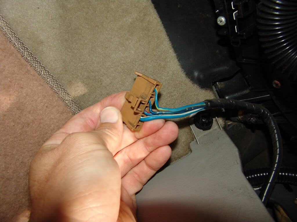
This 2003 Nissan Maxima came in with the complaint that only the highest blower speed was working. The air would not blow at all, on the lower speeds. Suspecting a faulty blower resistor, I went to the passenger side of the dash.
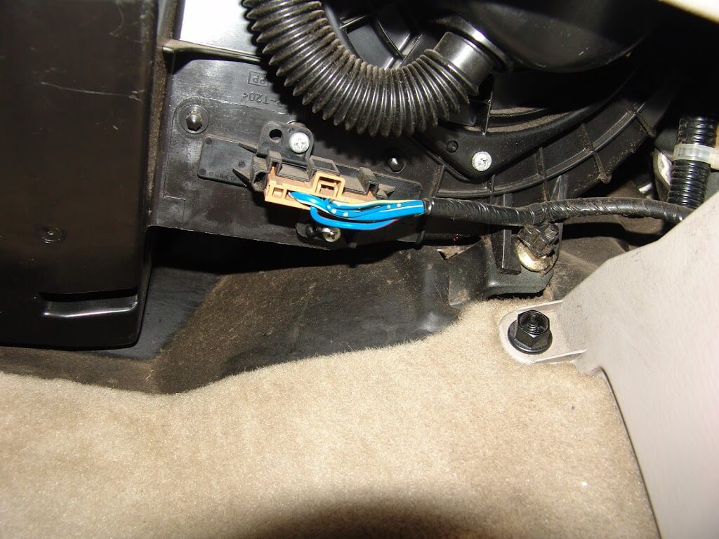
The blower resistor is located near the firewall under the passenger side of the dash. It is the piece that the connector with blue wires is attached to.
Two phillip’s headed screws hold the resistor to the blower housing.
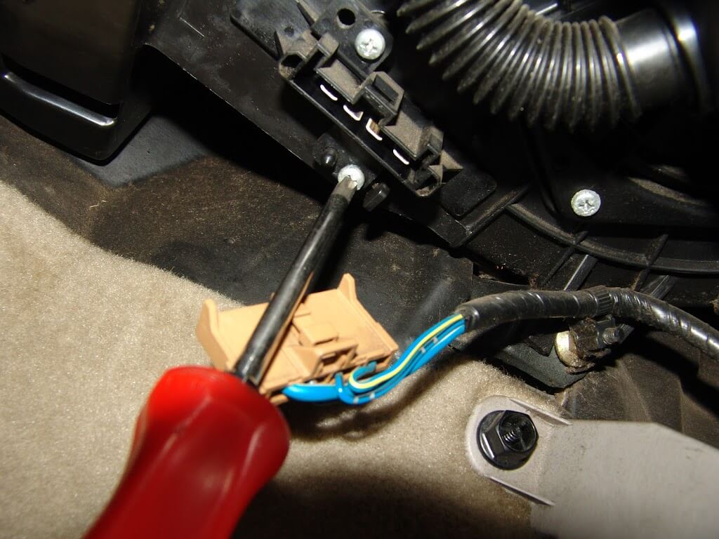
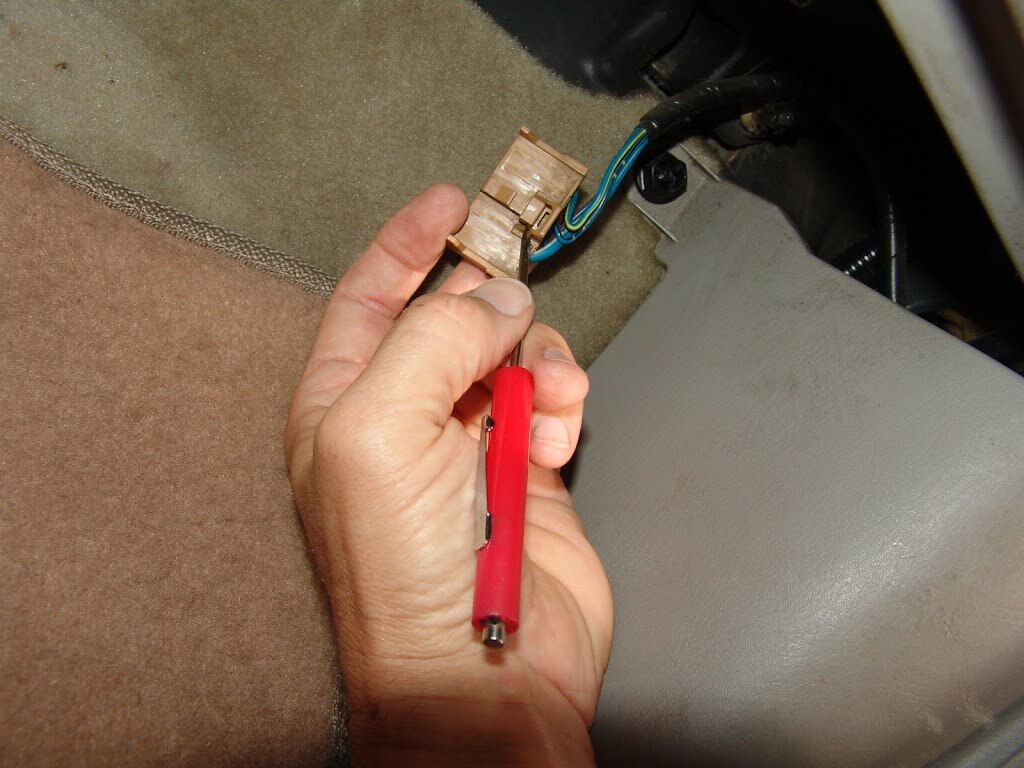
To release the locking tab, it needs to be pushed in where I am pointing at with my pocket screwdriver.
If you want to test the system this is what you will need to know.
The blower resistor and blower switch are on the ground side of the blower motor circuit.
With the resistor harness disconnected and the ignition on, there will be bleed through battery voltage on the larger blue/white wire. In the blower switch position 4 or high the blower switch directly connects this wire to chassis ground and the highest blower speed is achieved.
When the blower speed is set to the 3 position the ground is sent from the blower switch to the resistor on the blue/red wire. It passes through one resistor and the speed is reduced slightly.
When blower speed 2 is selected the ground again is sent form the blower switch to the resistor but this time it is sent on the blue/yellow wire. At the resistor is passes through two resistors and the speed is dropped even further.
When blower speed 1 is selected the ground signal again is sent from the blower switch to the blower resistor and this time it is on the blue/black wire. At the resistor is passes through three resistors and the lowest blower speed is achieved.
If there is no bleed through voltage at the blue/white wire you will need to see if there is power on the white/blue wire at the blower motor itself.
If voltage is not present on the white/blue wire at the blower motor you will need to check the fuses and relay. If power is present the blower motor is faulty.
I also wound up checking and changing a restricted cabin air filter in this vehicle. It is likely that the dirty filter contributed to the resistor failure.


")


")