Credit: Carlos Hernandez
OEM Part Number: 32865-AA420


![]()


")

Credit: Sam Jacobs
I promised I would do this, and here it is ages later lol. This is a write up on swapping an auto 5.5 Max to a 6spd. It’s off my memory and old posts, so I will add stuff as I remember. All pictures are on the bottom!
First thing is first, you will need all of the parts to complete the swap before even reading this. There are a few good posts on the Org which cover this. Basics of course are the transmission, shifter assembly and cables, manual trans mount, flywheel and clutch, clutch pedal spacer, clutch pedal itself, and a few other misc things I will add as I think of them. You DO NOT need to swap engine wiring harnesses. If you want to, go ahead, but Nisformance actually recommends not swapping any harnesses or computers.
Onto the process itself- I found myself a donor car, so my first order of business was breaking that car down for all of the parts- this makes things easier.
Step 1. Obviously, you need to cut loose all of the parts from your auto. This includes; The brake pedal, the transmission, the shifter and it’s cable, and cutting off the automatic trans mount. I only cut it on the side of the frame rail, no need to cut the top off, it assists with the strength of the metal.

Step 2. Possibly one of the harder parts of this job for me was mounting the master clutch cylinder. On my car, I had a patch in the firewall insulation on my auto car, but no holes in the firewall itself. What I did was mount the patch piece up to my donor car, and drew a couple holes. I then taped the piece onto my firewall and drilled two holes, followed by the large middle hole for the cylinder itself.
Do not worry about having the best accuracy here, the clutch pedal itself has two bolts under the dash. But please, TAKE YOUR TIME with this. The more precise you are, the better. When installing the clutch pedal and cylinder, be sure to install the spacer in between the firewall and pedal, there are spacers out there, but might not be any new ones left so you may have to get creative. Also install the brake pedal from the manual car while you are down there. Okay, now that your clutch pedal and master cylinder are attached, you can proceed to step 3.

Step 3. Mount your shifter assembly and route the cables through your firewall. What I had to do was cut the bracket that covers the opening a bit, and then I was able to make it work. Use Dynamat to cover the hole, or whatever your creative brain desires. You will have to find two bolts that fit through the trans tunnel as the studs the auto used, no longer exist.
IMPORTANT: Use loctite and lock washers, otherwise you will lose your bolts.
At this point, you should have the pedal/cylinder mounted as well as the shifter, that’s a good bit. You can now install your flywheel and clutch, see other posts for torque specs until I post them.

Step 4. Put the transmission in. This takes a lot of time and patience, esp if you have raised motor mounts. You can look up tips and vids on installing it. As far as mounting the bracket, there’s a couple options here. You can weld it on, or run two bolts through the top like I did. I wanted the part to be removable so pick your poison. This mount doesn’t really hold the motor/trans up, just keeps it all tight and straight when driving hard. Install your MANUAL transmission axles.

Step 5. It’s now time for wiring, this is easy, even for me who hates wiring. So you will see a few methods on wiring the car so that it cranks over. You do as you please, multiple methods work!!! But I suggest to wire it like a factory car. To do this, you will need to have the REAR connector off the clutch pedal. Take one wire and ground it, and the other wire needs to go to the INHIBIT relay in the relay box in front of the battery. You will be tapping into the
Green/Orange wire with the wire off the clutch pedal. This allows the car to function as it came from the factory, it will not crank without the clutch pedal depressed. Now you have to wire the starter. The automatic starter has the connector you need. Cut it off (as well as the one off the manual starter) and attach the auto connector to the manual starter.
You can now connect your shift cables to the trans, one piece clutch line to the slave cylinder (bleed it of course), and you should be ready to start the car.
Step 6. Wire in the reverse lights. On the auto harness, you will see 3 connectors that don’t plug into anything. The bigger of the 3 is what you use. Take the Green/White wire and put it to the green/white wire on the manual trans. Same for the Orange wire (I believe the orange wire you want is the one further from the green/white wire, I will update when I can). I cant remember off the top of my head which orange and which green/white to use. There’s two of each, so just experiment a bit. I can update this when I’m with the car again and have a picture.

At this point you should have a manual transmission car! This is the major steps, of course there are other components such as filling the trans with the PROPER oil, swapping clusters if you don’t want to see the auto gear letters, putting a manual trans shift bezel on, etc…
![]()

Credit: Joey Edwin
Installation Notes:


![]()

Credit: Jose Vargas
Parts that are needed for the BOV AN setup. These are the parts I used so it can route it the way I wanted, might be a bit different for everyone else depending how you guys have your BOV and location. I bought everything off of this site, I see they don’t carry 3AN anymore but it can still be done with 4AN as well. Post links with 4AN option.
1/8 NPT 3AN Fitting

Tapping this later today when my drill bit and tap arrive from amazon


Original nipple that was on BOV it is a 1/8 NPT


![]()
 Installed")
Credit: xHypex, Mishmosh, and Keven97SE
(Order not strictly important in some cases)
Mishmosh
Directly facing the IAC, this pic of the right side of theIAC shows the 10mm bolt that you need to remove to get the bracket out of the way of one of the 3 retaining bolts. That cable you see is connected to the EGR guide tube.

shows some butterfly’s installed. Pay particular attention to how the end of the rod lines up with the stopping plate (on the right). The butterfly’s are not sided so any side is fine. The rod has one side rounded and the other flat so there is no question which side to mount the valves.

Rear retaining bolt that you need to feel out and remove. 12mm

Side view with the stock intake manifold out. Key structures: Mounting brackets for the two manifold retaining bolts. EGR guide tube. Rear coolant hose. TB/CAI. throttle/cruise cable along firewall with that cylindrical structure attached to the firewall (which I removed cause it made position the new VI a little difficult).

Right rear side pic showing EGR: note the 12mm bolt and the fat washer. In the lower right corner of the pic, you can see the coolant hose. There is also another one on the other side of the EGR (out of view).

Side view of the installed vacuum actuator. Manifold vacuum fed from the Fuel Pressure Reg vacuum line down below >> Vacuum canister >> Switched port of the solenoid >> main port of the solenoid to VI vacuum lever.

Ground bolt–a convenient place to ground. (Credit: xHypex)

Relay that activates MAP switch. Can you tell which it is? (I don’t have ABS)

Vacuum Canister mounted near the strut mount (it will be painted soon)

Nissan vacuum canister adds to the OEM look

Nissan MAP switch

Nissan Check Valve connected to the FPR vacuum via a F fitting

After installing the VI your EVAP will not have a place to mount. On the ’99s the EVAP is a small electrical sensor and sits nicely on top of the manifold. 95-98s have a mechanical EVAP which is larger.

Vacuum actuator arm moves forward when the vacuum kicks in.

Side view

Here’s the FSM diagram of the MEVI

Large, Closeup pictures of the MEVI Collector


 MEVI Installed on Ian’s Car
N/A
MEVI with Cover on my car

Wiring Diagrams
(courtesy of Keven97SE and Mishmosh)
N/A
Alternate Wiring Diagram

FSM Vacuum Diagram

Ian’s Dynoes: Dyno Run 1 and 3 were baseline runs and on 5 the VI opened at 5k.
Dyno HP

Dyno TQ

Dyno HP & TQ

Spreadsheet with RPM, HP, TQ
speedtrip’s dynoes:
CAI/Y-pipe (baseline) CAI

Ypipe with VI Hybrid

Ypipe with VI

Spreadsheet with RPM, HP, TQ
![]()
")
")
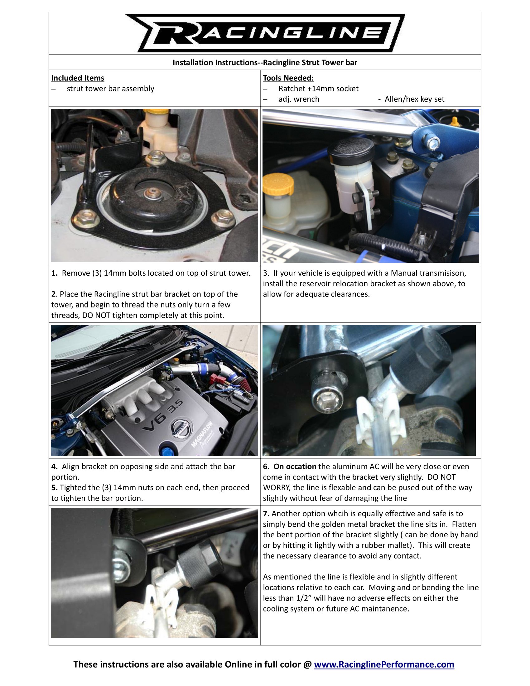
Engineered to perform where others have failed, Racingline Strut bars are engineered to be both classic in style and functional in design.
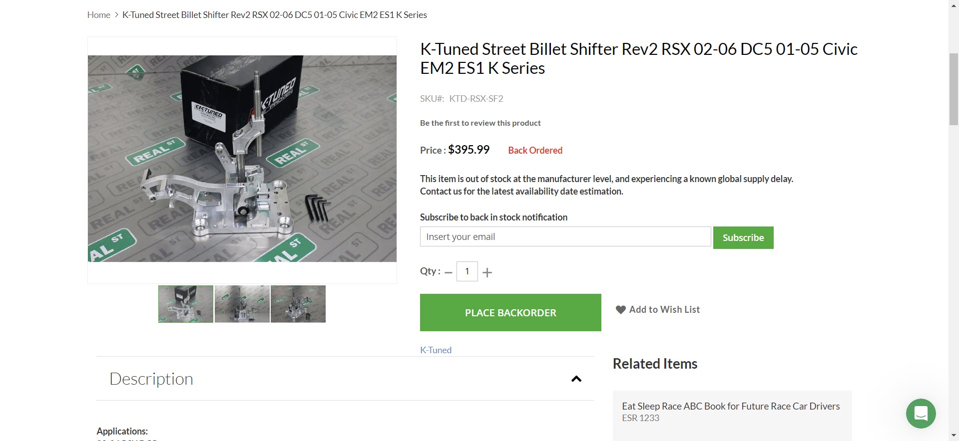
Price: $99.99
Designed to be a simple bolt on product, the Racingline strut tower bar connects the strut towers to provide for a more rigid chassis that rewards the driver with greater steering feedback and response. Along with the improved steering feel, better cornering ability and stability are also realized. Allowing the driver to more confidently control the vehicle during cornering maneuvers.
Ample space around the intake manifold is enough to accommodate popular IM spacer kits.
Internally the bar is divided into 3 chambers with 2 vertical walls to aid in rigidity, while maintaining the light properties aluminum is known for. Available in a high luster polish or semi gloss black.
Will fit both 3.0L and 3.5L equipped models.


PDF Version: 18631_Install
![]()
")
Motor Mount Inserts (MMI’s) Help to eliminate excess engine movement by stiffening the vehicles torque position motor mounts.
Price: $49.99
Used in conjunction with the original stock motor mount, these inserts will help to:
Stock motor mounts are made to be supportive yet limit vibration as much as possible to keep the car comfortable for the masses who buy them, not the performance enthusiast. In the attempt to keep the car soft, play has been introduced into the mount that cause damaging wheel hop and a lot of engine movement which can actually damage vehicle components during spirited driving. Shift linkages and gears can possibly be damaged due to the motors rocking motion and misalignment with the shift linkage.
MMI’s help protect against this by keeping the motor in a stationary position during high revving conditions and resist the motors tendency to “bounce” back and forth during shifting operations
SOLD IN SETS OF 2, these fit the lower front and rear engine mounts
Front only available for 5AT & CVT vehicles not wanting to lower subframe for installation. All other models can install as per instructions.


PDF Version: L31A34_MMI_Install


![]()
")
Motor Mount Inserts (MMI’s) Help to eliminate excess engine movement by stiffening the vehicles torque position motor mounts.
Price: $49.99
Used in conjunction with the original stock motor mount, these inserts will help to:
Stock motor mounts are made to be supportive yet limit vibration as much as possible to keep the car comfortable for the masses who buy them, not the performance enthusiast. In the attempt to keep the car soft, play has been introduced into the mount that cause damaging wheel hop and a lot of engine movement which can actually damage vehicle components during spirited driving. Shift linkages and gears can possibly be damaged due to the motors rocking motion and misalignment with the shift linkage.
MMI’s help protect against this by keeping the motor in a stationary position during high revving conditions and resist the motors tendency to “bounce” back and forth during shifting operations
SOLD IN SETS OF 2, these fit the lower front and rear engine mounts
Front only available for 5AT & CVT vehicles not wanting to lower subframe for installation. All other models can install as per instructions.
PDF Version: L31A34_MMI_Install
![]()
 Install on 2005 2.5L Nissan Altima")
Credit: shot_calla
Here’s something I wrote up and originally posted on nissanclub.
I have a 05 auto 2.5. I ended up spending 3 hours trying to install the MMI just for the front and was unable to get the mount back in with the MMI so just put the mount back on without it…
I took pictures during my attempt to install for a little writeup, although I was unable to get it to work maybe these pics can help someone else.
Here are the three 17mm bolts you need to remove view from underneath the car

View from engine bay of the motor mount

Once I removed the 3 bolts, I jacked up the engine a bit to get enough room to wiggle the mount out. I was able to pull the mount out going upward standing in front of the car reaching down into the engine bay.

Here is the mount removed next to the inserts, you can see the empty cavities (*Notice I received 2 front MMIs, Taz later sent me a new rear insert)

Here is the mount with the insert
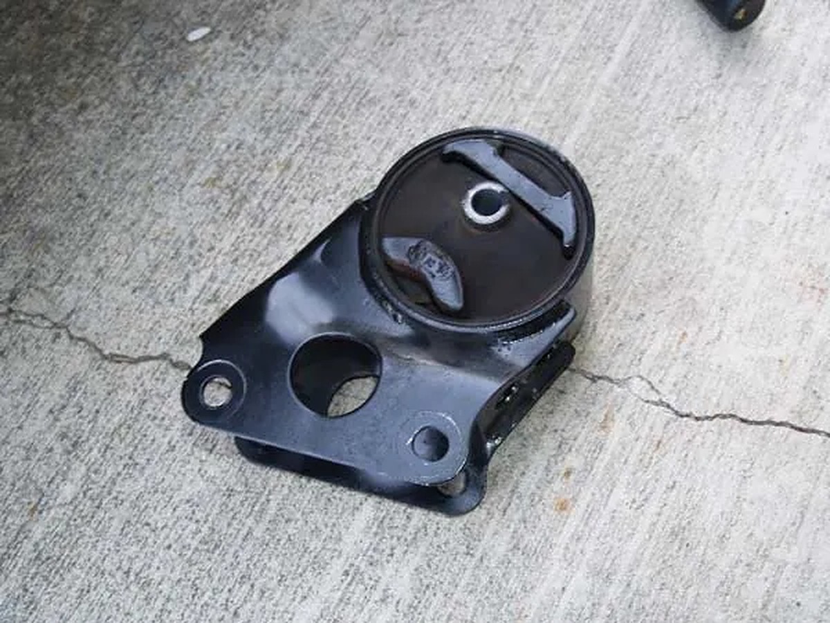
Here is a sideview of the mount with insert, the right side bulges out, and I had problems putting the mount back in.

A closeup to where the center bolt on the mount connects to, there is an area sticks out around the center bolt to prevent the mount from kicking upward. This is where I had problems fitting insert since it bulged out and it was hitting the center bolt area that sticks out in the picture below. I was trying to insert the mount back in from going down standing in front of the car reaching down into the engine bay.

I only tried to install the front mount on my 2.5 so far, I took a look at the rear and it was so cramped I didn’t even want to try… Like others has said, the install isn’t that long and I can see how the front should only take 30 minutes, but I usually take a bit more time trying to be careful and had problems so it took me quite a while…
I probably will have a shop install the rear and give the front a try another day…
![]()