How to Test: P1320-PLUG TEST
Part Number: 28351-89901
Description: CONDENSER IGNITION COIL
Price: $10.00 – $12.00


1995-1999 4thgen Nissan Maxima
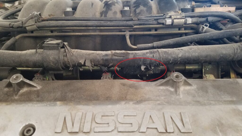
2000-2001 5thgen Nissan Maxima
2002-2003 5thgen Nissan Maxima

![]()


How to Test: P1320-PLUG TEST
Part Number: 28351-89901
Description: CONDENSER IGNITION COIL
Price: $10.00 – $12.00
![]()

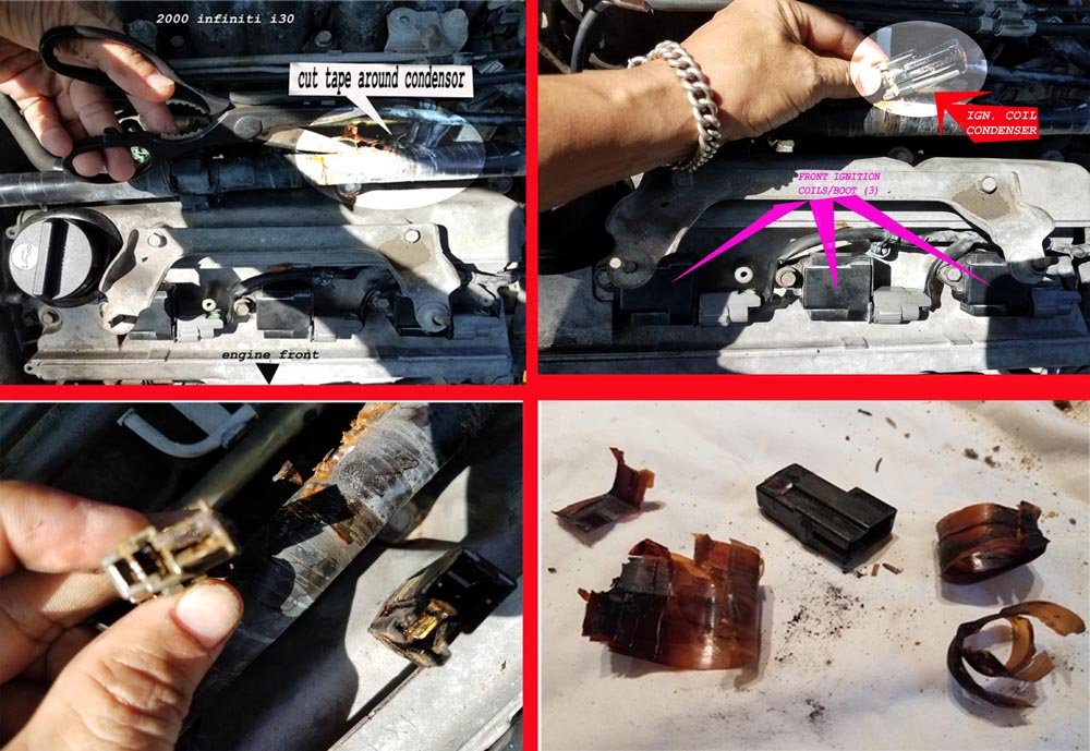
Community Member Credit: Eddy


![]()

Community Member Credit: shadyonedeath


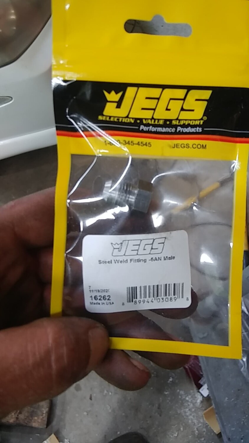
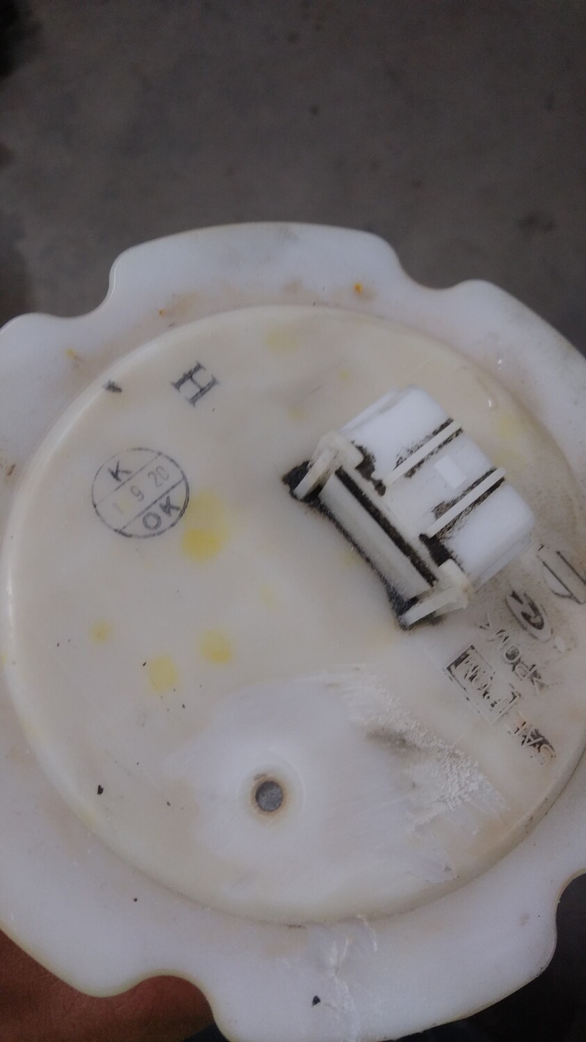
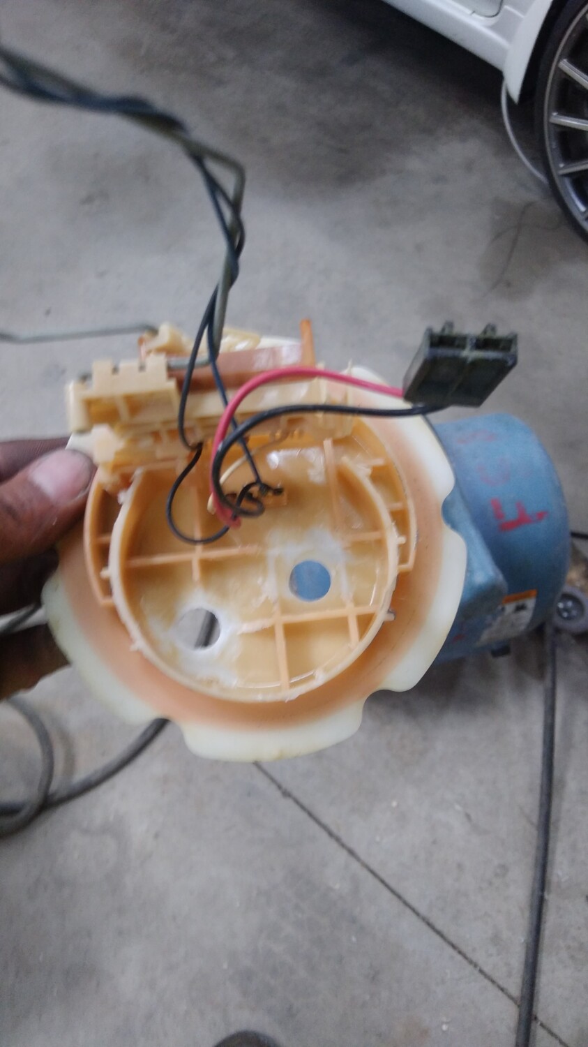
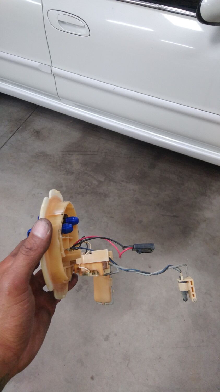
I collected parts for both 00vi setup options. 4th gen LIM setup and all 5th gen LIM setup. Both of them would have used a 4th gen IACV and adapter. I am going with 5th gen lower because I decided the UIM was designed for the 5th gen lower, and I don’t mind tuning it when using the 5th gen fuel rails.
MY Swap Project:
Prepping the UIM

If you were like me, your junkyard/delivery man wasn’t too friendly with the UIM. As you can see my first UIM has the majority of nipples broken. Good thing we they’re inadequate for our 4th gen vacuum lines and we need to replace them anyway…

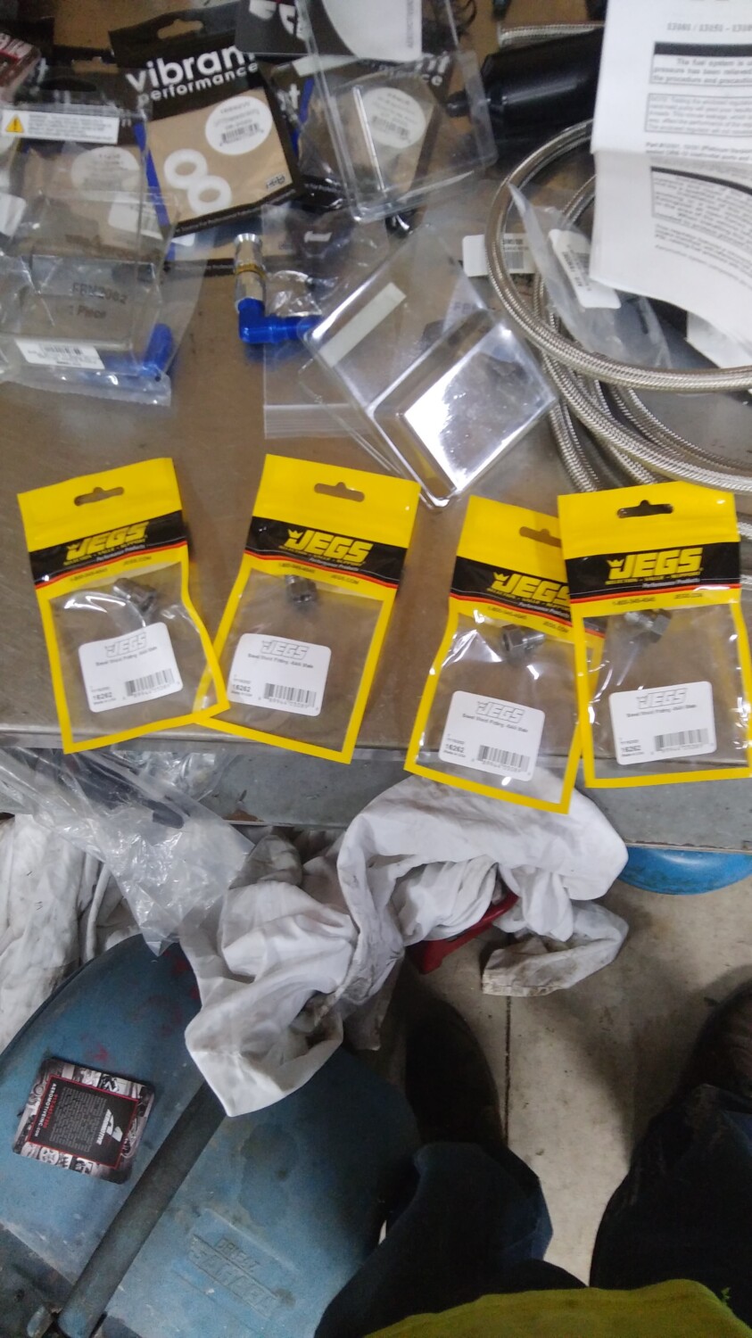
Here is what I will be using.
Materials: From top to bottom of the picture
Note: Ignore the Straight brass fitting in the picture. Didnt use it. 90 degree bent elbows work best. I used two 3/8″ x 1/4″ elbows and one 1/2″ x 1/4 elbow.
The straight 1/2″ barb is for the IACV adapter.
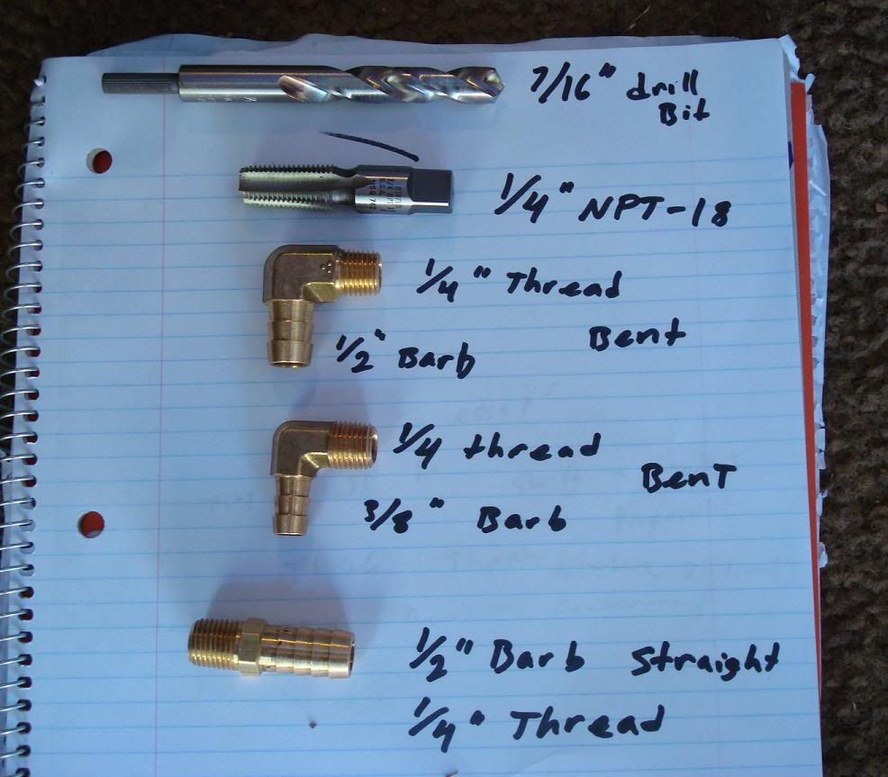
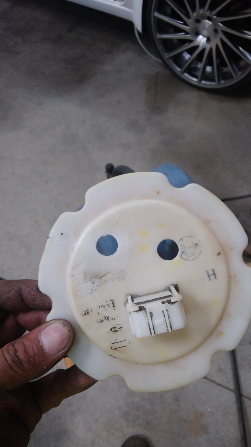
Lets start with the EVAP line located on TOP of the UIM where the Throttle body bolts up. Number (4) on the Diagram.

Damaged tower but still has plenty of meat to work with. First step, drill it out using a smaller 3/8″ drill bit, and move up to a 7/16″ bit to reduce stress. The 1/4 NPT-18 tap requires a 7/16″ hole.

Note: Either this plastic material is super fragile or my tap was razor sharp, but it cut through like butter. Make sure you know how deep your tap has gone so you don’t accidentally ruin your threads by over-turning it.
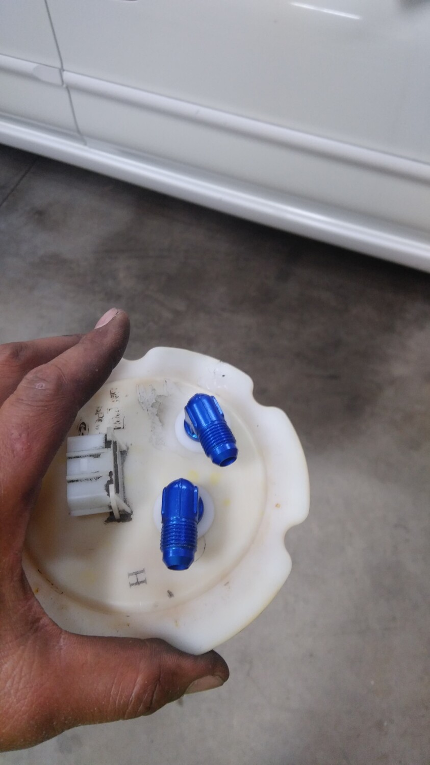
Result. Make sure you use some tweezers to pluck off excess plastic and prevent it from getting sucked in to your car later. Once its all clean, insert your 3/8″ barb x 1/4″ threaded brass fitting here, and your done. I also used RED permanent loctite (thread lock) to seal it up real good. You will probably want to use some RTV instead of loctite. I didnt, but i will if i encounter any leaks during the install.

Next, the brake booster line. Number (1) in the diagram.. Cut the existing nipple flush with the wall of the manifold and drill using 7/16″ bit. Careful, don’t go too deep, not a lot of meat in there, and you’ll quickly hit a wall inside the manifold. Just drill enough to widen the hole for tapping.


I then pulled out the rubber cap covering a small nipple underneath the brake booster nipple and cut it away enough to allow my brass fitting to screw in. Don’t cut it all the way to the wall like the brake booster nipple above it, leave some nipple there and cover it back up with the rubber cap along with some sealant. This will avoid the hassle of sealing it up with something like JB weld and getting sucked in.

Last, the IACV line, port 5 in the diagram. The brass elbow used is a 90 degree 1/2″ barb x 1/4″ threaded brass fitting that’s required to give enough air flow to the IACV adapter to prevent idle issues. I used a hacksaw to cut the tower behind the existing nipple. I then used my smaller 3/8″ drill bit to enlarge the hole, followed by 7/16″ drill bit. I then used my tap, and ended with the brass fitting and some loctite.
Edit: Don’t use Loctite. When it dries, it gets hard. Hard = cracking if you later want to re-position the nipple in a different angle. You dont want pieces of loctite in your engine. If i were to do it again i’d use High Temp RTV. Its orange and flexible when hard.


Note: These brass fittings are a ***** to get in. Once you’ve twisted beyond the strength of your hand, use a wrench to torque it in there.
Both fittings shown. The reason the top tower for the EVAP is still in tact is because i need to get another 90 degree 3/8 barbed elbow but the hardware store is closed. I WAS going to use the straight one but the hole that supplies that tower with vacuum is too small. I need to cut it off completely and enlarge the hole all the way through the manifold. Also, the process shown in the first drilling of the EVAP line was from my 2nd manifold which i will be selling. I prepped both manifolds for threads but only installed nipples in one.

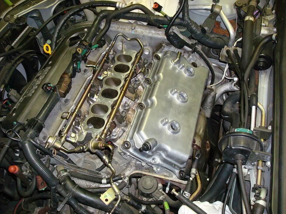
Update: Top tower fitting installed

Painting 00vi Upper Manifold
Materials:
Process:
Pretty simple: sand smooth, clean with rubbing alcohol, mask important areas with tape and paint.

Here I used some left over graphite colored wheel spray paint and “flaked” it from a distance to give it a diff. look.


00vi Swap : The Removal I recommend getting your models Factory service Manual for reference.

If you’re attempting the 00vi swap you should be fairly familiar with what needs to be removed and how to remove them. I’ll try and go through the basics. Also, before you start, i recommend your protect your fenders with some type of cover between your knees/clothes and the paint. I used some brown wrapping paper and Painters tape to cover both fenders and areas pained near the engine bay. I also recommend you label your hoses and there they go. Use whatever it takes because no matter how good you think your memory is, you WILL lose track of dangling hoses.
A – Battery
B – Air Box
C – Mass Air Flow Sensor MAF (Handle with care…we don’t need more problems when troubleshooting your 00vi install)
D – Throttle Body – 4th Gen TB’s have a) Throttle Cables, b) Coolant lines (I plugged mine with bolts removed in the process to prevent spilling), c) Connectors (Throttle Position sensors, Brown and Black/Gray) that need to be removed.
E – Electrical log/Harness – This connects to: a) Coil Packs, b) EVAP valve c) EGR temp sensor, d) EGR unit itself, e) Throttle Position sensor. Remove these and the log can be bent out of the way towards passenger side of engine bay.
F – Upper Intake Manifold – Mine had 4 bolts up front towards bumper and 4(?) in the rear attached to mounting brackets. Stick your hand back there and familiarize yourself with the brackets and the number of bolts. Not 100% sure how many there are back there. UIM also has the throttle cables mounted to the bracket, loosen the cables and they slip off the bracket. If your 00vi didnt come with a bracket, avoid removing the cables and just remove the bracket itself and push/tape out of the way. The EVAP valve is also on top of the UIM, remove it and get it out of the way. Your PVC line will also be attached to the UIM, remove the vacuum hose. Behind the UIM, your EGR tube is attached, there are 2 bolts holding it. Under the EGR tube are 2 short coolant lines that run through the UIM. I didnt bother removing mine properly due to the tight space, i just took a knife to the hoses since I replaced the two EGR coolant lines and make a “UIM/Throttle Body coolant bypass”. Remember to note which one Runs coolant and which one Returns it, they lead back to the coolant log near the front Valve cover/ Knock sensor connector cable.
G – EVAP valve
H- Not visible in picture but this is where you Idle Air Control Valve is. (IACV)


(ignore the “stand alone” label)
Here is your EGR tube removal since you need to use the 5th gen EGR tube with the 5th gen Upper Intake Manifold. I used a Dremel and a cutting wheel to cut the stud tip off. This is necessary to remove the nut holding the EGR tube itself, since that brass looking tube is in the way. I’ve read you can also cut it using a hacksaw blade…without the handle. Might take a while though. Make sure you plug/cover your fuel lines before grinding away here to avoid any unwanted ignitions.

Rear valve cover and Lower Intake manifold
Pretty straight forward, unbolt and replace. Use new crush gaskets for the LIM and if your Valve cover gasket is still good, use some Ultra Black RTV. I failed to do so and had a oil leak, had to remove everything, clean the oil off the gasket/valve cover, and RTV the gasket into the valve cover grove, then RTV on the gasket to the head. For the LIM, i took my time torquing the bolts, little by little, starting from the middle, outward. Search for the torquing procedure on the org or in your Factory service manual. Same with Rear valve cover. Also, inspect your new rear valve cover’s rubber grommets. There’s four, 1- PCV, and 3 for spark plug tubes.
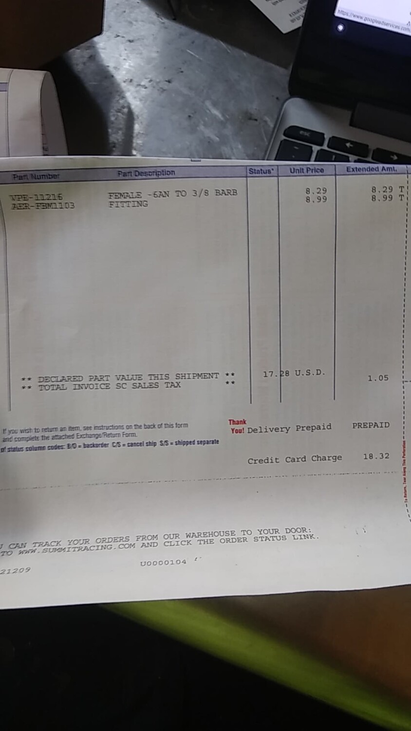
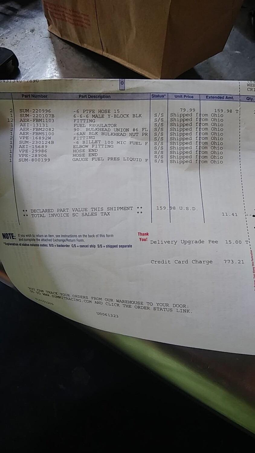
Fuel Lines:

Ignore the tags. (VAFC2 Vafc 2 VAFCII VAFC II )
I bought my Apexi VAFC2 used and it was missing the 20 gauge extension harness. The wires on the main unit itself are VERY fine, above 22 gauge, and would not be easy to work with when splicing into the ECU.
What I did was take a old Computer Power supply and use the 20 gauge wires as an extension/adapter for my splice connectors.
Materials:
-Splice connectors. Can be found at radio shack.

-Soldering iron / solder
-electrical tape
-Wire stripper
-Wire cutters
-Sacrificial Computer Power Supply Unit wires
-VAFC2 harness (the VAFC2 is inside the glove to protect it… )
-wet sponge (cleaning iron tip)

Note: If i could do it again, instead of cutting wires off the Power supply unit, i would have cut off an entire Power supply unit harness with connectors attached and used that as a removable connection to my VAFC2. The PSU clips would have been useful.
First, i started stripping ends of the PSU wire. If your lucky, you’ll find matching colors to your VAFC2 harness. I found all of them except for brown and pink. For brown i used Black, as it is a ground, and Orange for Pink.

To strip the super thin wires from the VAFC2 harness itself, i used a new razor blade and gently twisted it around the wire. I then bent the wire to expose the cut and pulled off the insulation with my finger nails. Use common sense on applying pressure on the blade.

My method of soldering is pretty amateurish but i don’t care. As long as you make a solid connection, any method works. I just twisted both ends of the wires and bent the tip back with pliers.

Followed by solder.

I then used electrical tape to seal the connections. Others will suggest heat shrink wrap but i couldn’t find any @ Home Depot, radio shack, or auto zone. The result.

Note: Maxima’s DO NOT use VAFC2 wires: ORANGE, LIGHT BLUE, and PURPLE. I covered each tip with electrical tape and then taped them all together and stuffed them back in the main insulation on the VAFC. See diagram in next post for wiring.
Before you do ANY of this, make sure you disconnect your Negative battery terminal before you work on splicing into the ECU.
Here we have the wiring. There are two power wires (red) and two ground wires (one black and one brown) required to function the VAFC2. Each set is spliced into the same Power or Ground in on the ECU harness and spaced apart 1cm or more. The MAF wire on the ECU harness must be CUT, not spliced. Once cut, the end still attached to the ECU CONNECTOR/CLIP is connected to the YELLOW wire on the VAFC2 harness. The other end of the MAF wire we cut is attached to the WHITE wire of the VAFC2 harness.
Refer to YOUR Maxima model’s Factory Service Manual for correct wire colors on the ECU harness. Wire listings can be found in section EC under ECM Terminals and Reference Value.
Note: I haven’t messed with the MAF wire yet because i need to get some plugs for the wiring. These plugs will allow the MAF wire to be reconnected to its original form easily should you choose to remove the VAFC2. Also it helps make a cleaner and secure install. I also avoided splicing into the Knock Sensor wire, apparently this caused some issues with the car starting and previous installers have avoided this part of the install. Please correct me if im wrong on this.
Edit: DO NOT use knock sensor wire. We dont need it. – per gtr_rider. Its not designed for our cars

Go to the Passenger side and remove the cover concealing the rear of the ECU/ECM. You will see a white plastic cover over the wire harness. Use a 10mm socket wrench to remove the bolt and then proceed to remove the harness/clip from the ECU. Once off, give the harness a bit of a tug to expose more working space. Nothing to drastic, just enough to get an extra inch or two. Remove the white/clear plastic cover from the harness clip using a flat head screw driver. Now we can begin searching for our desired wires.

Splice connectors are pretty self explanatory.

Don’t ask me how im going to get the plastic cover from the ECU harness back on, i probably wont.
Plug ECU harness back in, bolt it on, and reconnect your negative battery terminal. Turn key to ON position and if all connections are correct, enjoy your working VAFC2. I did it on my first try.

Note: The Yellowand white wire above are for the MAF wire. I didn’t get to this yet as i need some plug connectors. The Blue wire i believe is for a Wideband 02 sensor for tuning. Don’t have this yet, so also not used. The Orange wire you see is actually routed to the PINK wire on the VAFC2. PINK wire is used to send the 12v signal to the VIAS to activate the 00vi.

All systems go. At first my RPM signal wasnt working. I went back and made sure the tachmeter connecter was fully spliced using a pair of pliers. It did the trick and everything functions correctly.
I finally got some more brass fittings from ebay. My local source ran out of them and they were getting a bit pricey. (5$ a elbow). I got (6) 3/8 x 1/4 elbow fittings for about 10$.

Why six? Well, i need two for the 2nd 00vi im going to sell, 2 for my oil catch can, and 1 for my current 00vi, which i painted in above posts.
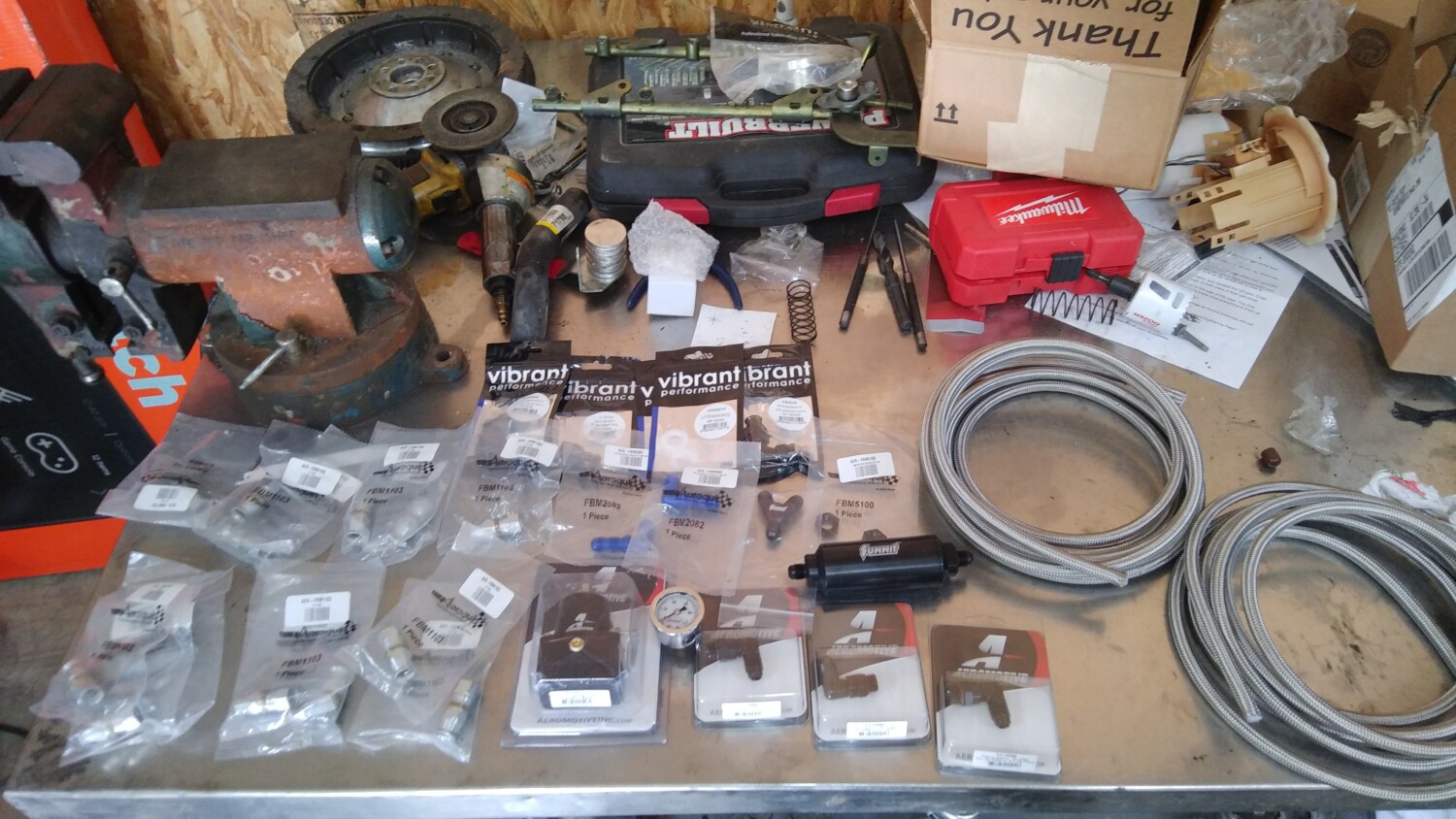
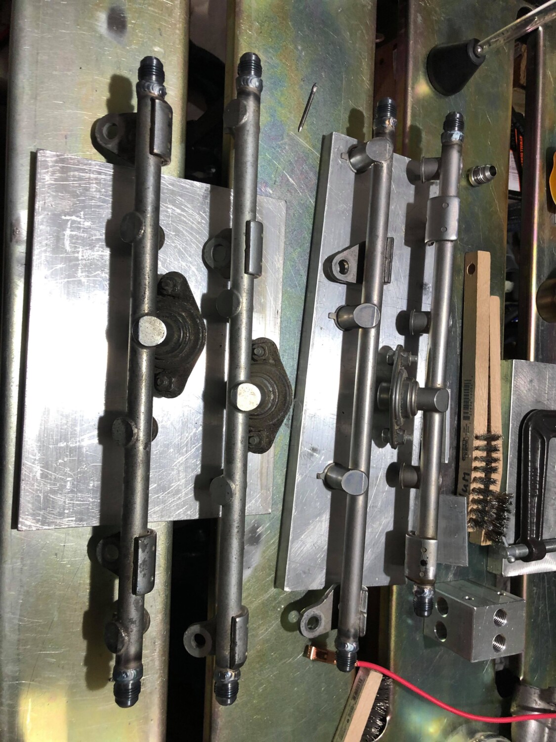
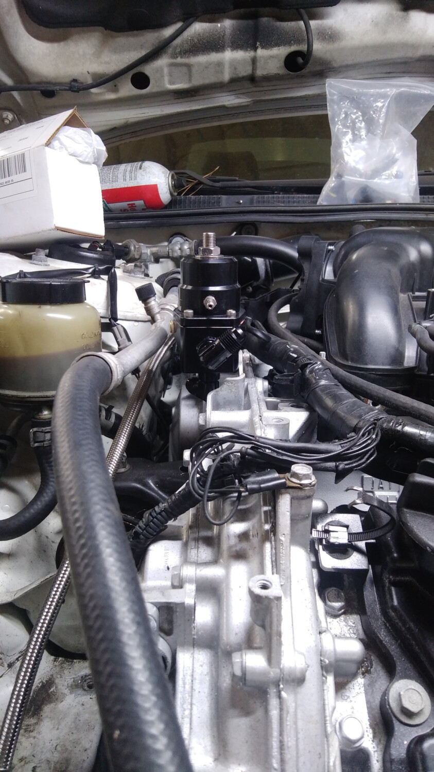
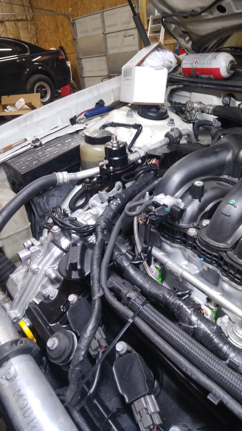
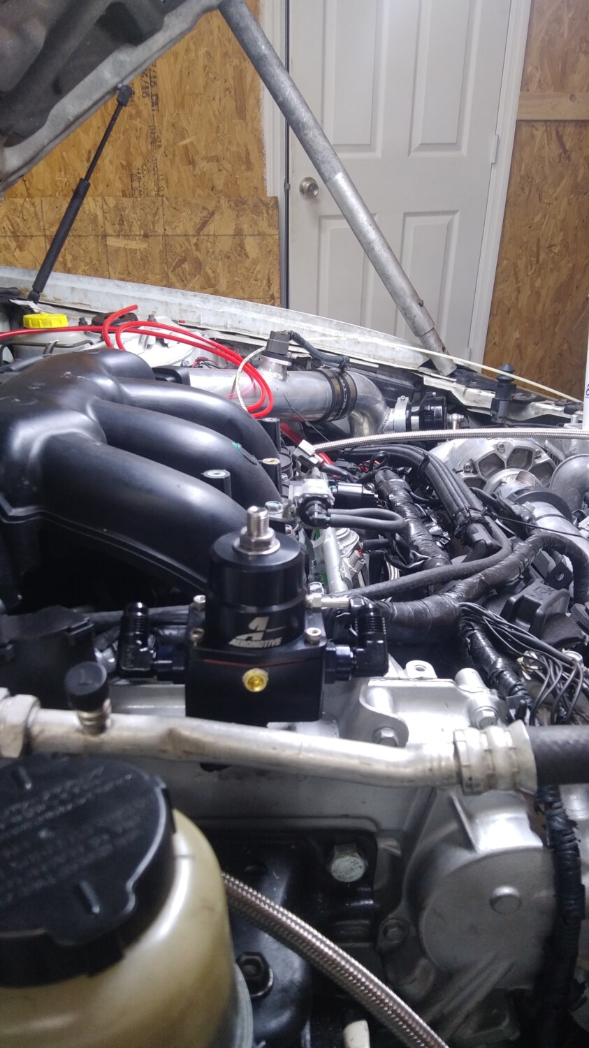
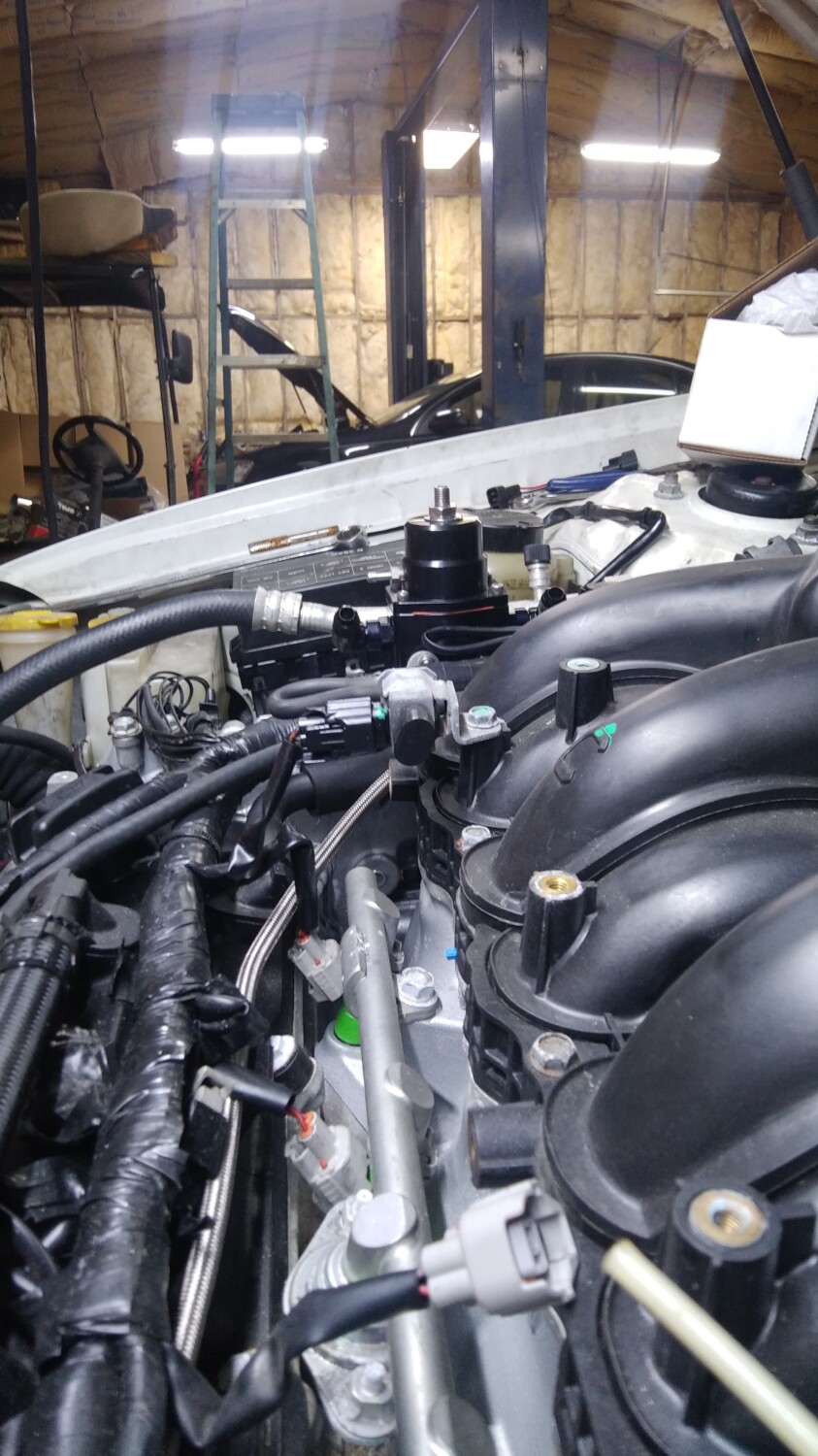
-5th gen Upper intake manifold
-5th gen Lower intake manifold
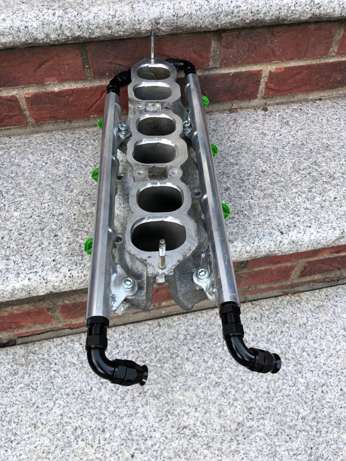
-5th gen fuel rail w/Damper and FPR, No adapter.
-5th gen FBJC100 290cc injectors
-5th gen Throttle Body
-5th gen Rear valve cover
-5th gen Rear Coil packs
-5th gen Snorkel & Air box modified to fit 4th gen MAF
-IACV Adapter
-4th gen Idle Air Control Valve
-Apexi VAFC2
-Husky (Home Depot) Oil Catch Can

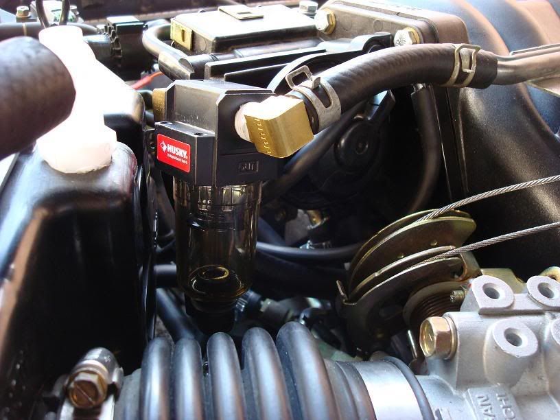
![]()
")
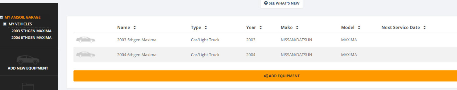
Article By: Eddy
I just wanted to share my experience with buying Amsoil products for my Nissan Maxima’s. Various Maxima friends have asked me where/how to get it at the discounted pricing. I’ve been using Amsoil products for about 7 years now with great results. At first, it may seem like all Amsoil products are “very expensive” but in reality, they are not. If you become a preferred member which costs $20 (yearly membership) you can save a decent amount of money. Since I have various cars, I buy in bulk to take advantage of their $100+ free shipping offer. I buy both engine oil and transmission fluid from Amsoil. If you have multiple cars and want a quality oil for your car, the $20 membership is worth it. I usually receive all the products within 2 days from ordering (FAST SHIPPING).
If you do not want to spend the $20 bucks, you can buy through a dealer. I personally prefer getting it on my own and as I need. You can check their website on how to become a dealer as well. With the preferred membership, you can also buy for your friends and family at the discounted rated.
In addition to saving 25% on Amsoil products you also get the following:

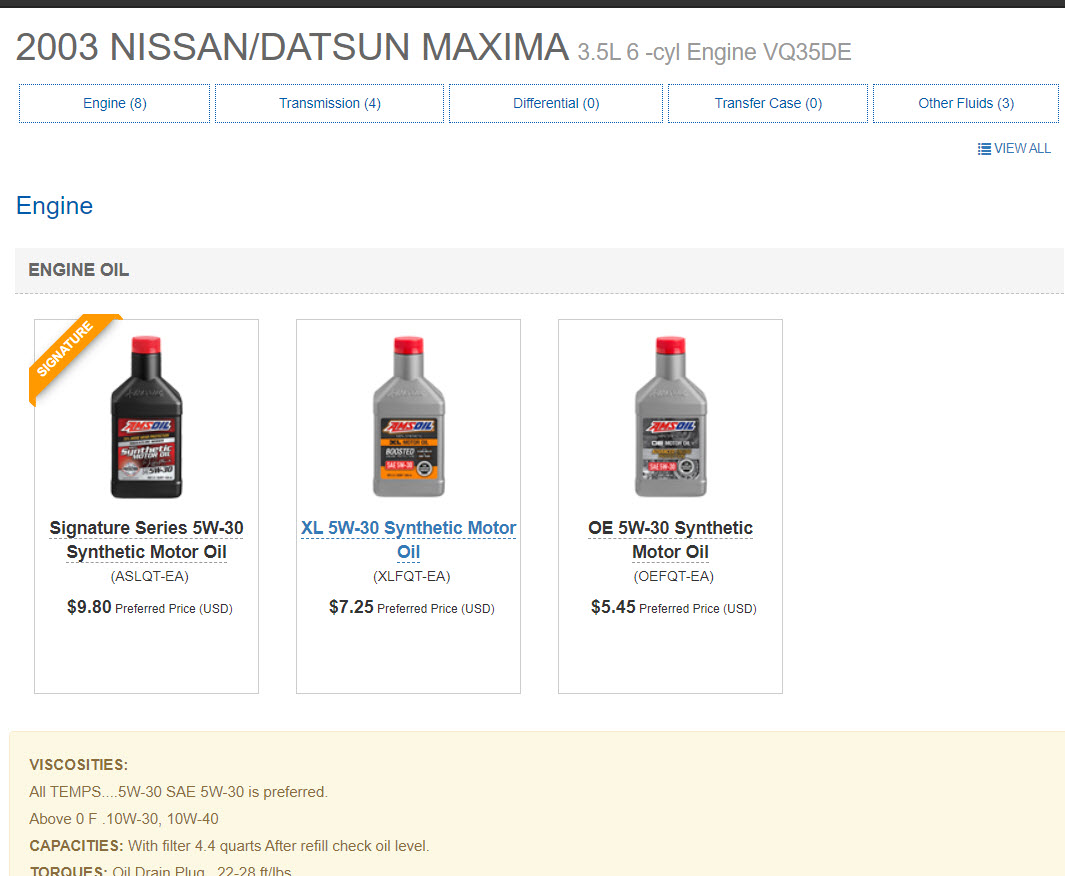
You can also track your maintenance and service intervals. It will send you alerts and email reminders which is pretty cool.


![]()

Community Member Credit: luke95gxe
So I decided to install a cold air intake the diff is noticeable and I love it.
Tools Needed
Parts Needed
My ram air intake set up:

Here is the pipe I used. It was beaten up so I painted it.

Remove fuse box and battery on driverside drill pilot holes and cut a hole a lil bigger than 3” in diameter.

Remove drivers-side wheel

Remove the splash guard by Phillips head screws you don’t have to completely remove.

Install cold air piping through the hole

Install air filter

Put splash guard back on and wheel and enjoy a better breathing engine. Finished product
I can definitely feel a difference on pulls than the ram air intake feel free to comment sorry for the crappy pics taken with my cell phone.
![]()

Community Member Credit: justmax
Basically this is a mod that short-circuits the Cruise control relay that requires you to turn on the toggle switch on your dash to the left of the steering column…
What you’ll need:
1. A couple of inches of 14-gauge wire (16 or 18 might work, but I didn’t want to risk the wire melting)
2. A couple of crimp-on flat spade connectors
What to do:
Attach the spade connectors to either end of your wire, like this:

Open up the relay box on the passenger side of the engine bay, you’re looking for the slot that has ASCD (Automatic Speed Control (Device):

Remove the ASCD relay from its slot (a small flat-head screwdriver will help you with the clip that holds it in). Now insert your wire into the connection that is perpendicular to the other 3, and the connection opposite that, like this:

Put the cover back on the relay box and put your unused relay away, cuz you’re done. Now the cruise control will be on whenever the car is on.
![]()


Order Link: https://www.2j-racing.com
Price: $99.99
2JR introduces our lightweight race pulley for the VQ35 Maxima and Infiniti I35, 01-04 years. Based on a far better design than the OBX pulley with a 75% weight savings over OEM, this is a must have mod for your VQ. Gain upwards to 9WHP / 12WTQ. Offered ONLY in anodized BLACK, with 2JR Logo.
2002-2006 Maxima Belt Size
2007-2008 Maxima Belt Size


![]()

Community Member Credit: luke95gxe


The first thing u wanna do is remove your intake to get some room

Then u need to hook a rubber hose to the bleeder valve on the slave and put the other end in a bottle to catch brake fluid.

Go ahead and open that bleeder 10mm take the cap of the master cylinder reservoir and let it drain out crack the upper bleeder open 12mm to speed up the process.

Then you wanna remove the slave cylinder (2 14mm bolts). You could probably leave it on to remove the old hose from it but it seems easier to remove the whole slave if you have a strut bar remove the driver side (3 14mm nuts) for room.


Once you get that out of the way go ahead and remove the 12mm bolt on the slave to remove the old hose then move up to the master cylinder.


Remove the old hard-line from the master cylinder 10mm. It’s tight right there but I managed it then you can hook the new ss line to the master cylinder mine was an 11mm nut yours may differ.

Then route the line where u want it and install the other end to the slave cylinder.

Once u do that you can do one of two things leave the old clutch lines on the car or remove them. I took mine out looks cleaner. I took some pics but remove them from the car is pretty easy here are the pics disconnect this

Remove the 2 10mm bolts here

There is a junction box right under the brake master cylinder where all this junk meets just unbolt and remove.
Now you need to bleed the line once that’s done enjoy a clutch line u shouldn’t need to replace.
Now let me say this I can deff feel a difference. wife drove it and says that the clutch pedal feels a lot tighter and more responsive best 25 bucks I spent. I recommend this mod to anyone with a 5 speed.
![]()