Tag

Engine

Browsing

Community Member Credit: CS_AR

Today I finished refurbishing the metal water pipes that run along the left side (e.g. nearest the radiator) of the engine.

After sanding and refinishing the pipes, I used some ceramic VHT exhaust header primer and paint that I had leftover from the Y-pipe. I’ve been slowly baking the pipes this afternoon to cure the ceramic paint before I do the installation. I’ve got to make sure the ceramic paint is fully cured and hardened before installing the o-rings and heater hoses. I did have to spend quite a bit of time sanding and polishing the hose connection areas to smooth off some rust that had formed between the hose rubber and the pipe. We’ll see how well the refinished hose and o-ring connection areas will hold up over time. The pipes are now in better condition than when I started.

Here are a couple of pictures that we may want to reference when someone has a water leak or needs to replace the o-rings or gasket. I like the Felpro gasket with the extra “red seal” area for the aluminum hose manifold mating surface. In the end, I reused some OEM o-rings that I already had on hand. I recommend using OEM o-rings as they will be the correct size.

I used 0000 steel wool to polish the aluminum pipe manifold o-ring and gasket mating surface areas. I might have been better off buying some new OEM pipes that come with a factory powder coat. But we can see how long the refurbished pipes last in the meantime.

Pardon my phone camera, as the pipes are actually a silver metallic color that matches the aluminum pipe manifold part.

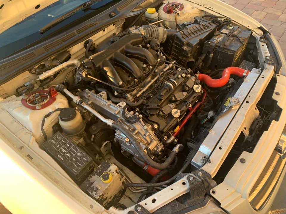
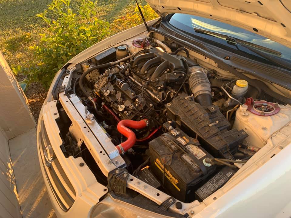
Here are a couple of pictures with the refinished pipes on the car. Valve cover polishing was still a work in progress when I took a break to snap the following picture.

I changed the 10mm short bolts pipe mounting bolts to use hex cap heads with lock washers in the picture.

Refinishing the pipes baking the ceramic paint has been a small project in itself. The only reason I attempted it is the easy-to-reach location if something backfires on me. A

s a side note, the OEM heater supply pipe on a VH45DE comes nickel-plated from Nissan. So all I had to do when I got a new one was to polish it up a bit and then clear coat it for the long haul. On a VH45DE the pipe lives at the bottom of “death valley” buried under a Gordian Knot of hose and wiring harnesses. You don’t want to miss anything that could come back as a leak or a problem after you put one of those critters back together. You can see it in the picture below the supply pipe running underneath the short pieces of head coolant hose.

Here are a couple of pictures with the refinished pipes on the car. I sure hope the o-rings hold up. The pipes felt solid and I could tell the o-rings were sealing the connections.

Valve cover polishing was still a work in progress when I took a break last night to snap the following picture. More to come with engine details about the coolant crossover pipe.

The original 10mm mounting bolts were changed to use stainless hex cap heads with lock washers in this picture. If possible, I like to use this type of bolt for coolant and fuel connection bolts.

Fortunately, the 99 model (with a 95 model engine) where I refinished the pipes, had under 80,000 miles. I didn’t notice any rust on the inside of the pipes. The pipes came with an engine from a local car that had been in a bad rear end collision. I bought the motor and had it installed in the 99 model.

This year, I took the pipes from the 99 model’s original engine with under 170,000 miles and refinished them for the 98 model with over 235,000 miles.

There is a 2nd thread on this topic, where I refinished the pipes from the 98 model. Those pipes are some of the worst that I’ve seen to date. In the time frame for the 98 model project, I discovered soaking metal parts in muriatic acid removes rust in a hurry.

I think the quality of water that is mixed with anti-freeze to make coolant has a lot to do with the formation of rust or barnacles in a cooling system.

The 98 model lived in a part of the state when iron deposits in the water so high that people use water softeners to condition the water for indoor use. The iron content in that area’s water will stain plumbing fixtures unless the water is conditioned before use. I could see that in the cooling system when I had it open.

One of my cars, lived for many year in a part of TX that must have had a lot of sulfur or calcium in the water. I found crusty mineral deposits inside its cooling system.

Even though the area where I live has good water that does not require conditioning before use, I like to use a 50/50 mix of distilled water and Xerex G05. After seven years of use on all of my Nissan products, it seems to work.

So here’s a picture of the acid bath where I cleaned up some pipes and put them away in my workshop for another project. Naturally, some light surface rust has appeared on the freshly cleaned pipes because I didn’t prime and refinish. I have an EGR pipe that I will treat sometime later in the year. I have another VQ30 from an I30 that I will be semi-overhauling to have on the shelf in the event I need a replacement engine.

Here’s a picture of the pipes that were refinished in this thread almost 3 years later. I am satisfied with how they are holding up. No surface rust, no complaints, and low maintenance.

I see a coolant flush product advertised for removing rust. This seems to be more popular with iron block engines.

If you find one that you think is safe to use on an aluminum engine, you might try it. One thing to note is acid and aluminum do not get along very well.

An aluminum part that is submerged in a muriatic acid bath that is strong enough to remove rust from metal parts, will fizz like an effervescent tablet. You can watch your part turn dark and start to dissolve right before your eyes. So I would use caution with a coolant flush that was designed for iron block engines that contains a lot of acid.

On one aluminum engine car, I used vinegar like the guy in this video. Though I followed it up two or three distilled water flushes to neutralize the vinegar before refilling with Zerex.

Many years ago I would see some coolant flush products shorten the life of water pumps. So I’ve always been hesitant to use a lot of chemicals to flush a cooling system.

Loading

Community Member Credit: KRRZ350 / MrCurst

Step 1: Remove #1 coil/plug and position #1 cylinder at TDC on the compression stroke.

Step 2: Remove upper half of engine mount and anything else that might get in the way of step 3

Step 3: Remove tensioner inspection cover.

Step3: Compress and lock the tensioner, then remove it.

Step 4: Using a 19mm socket, rotate the crankshaft counterclockwise until you hear the chain skip a tooth.

Step 5: Re-install everything and verify correct ignition timing and vacuum reading

This only applies if you skipped timing upon initial cranking, and only if it skipped on the crank sprocket, but I believe that’s where it skips every time.

Additional Notes:

  • If the chain jumped some teeth, the ONLY way to fix it is by removing the outer timing chain cover, setting the engine to TDC, removing the chain, then set your camshaft gears to the proper timing marks, make sure you are still at TDC, and reinstall the chain and check the alignment against the FSM. You can not adjust your engine timing with the cover and chain still on.
  • The Cam Position sensor controls fuel injection timing. Both crank position sensors control ignition timing.
  • If your chain has jumped a few teeth, I doubt the motor would even run and you should be throwing CEL codes for both cam and crank sensors and they would definitely be out of phase.
  • Indeed. 99% of the time if the chain jumps, it won’t run. However, if it goes one tooth off (I forget on which of the sprockets), it’ll run, just without cylinders 2 and 3.

Loading

Community Member Credit: mpvibes

So, I decided to go ahead and do the dreaded water pump replacement job on my EDIT: 263,000 mile 4th gen. What a PITA! I had to do it the long way because #1 I had a leak on my timing chain cover and # 2 I wanted to make sure my timing was accurate and my car didn’t jump timing, bend any valves, etc. Well, since it was my first time ever doing this job, it took me 2 days and I did learn a lot. Man, my oil pan and all my timing chain components were covered in oil sludge, it was ugly I had to do a lot of cleaning, using gasoline! Well, here are some pics that I wanted to share with you all. Sorry for some of the crappy pics…

UPDATE: When cleaning and putting on the lower oil pan just get a NEW Felpro oil pan gasket and follow the tightening sequence! Do not put RTV silicone on there. I had a leak and had to get a Felpro gasket.

New Nissan Water Pump

Oil sludge all over timing components

Broke the old water pump while taking it out

Cleaned and looking good!

Old Thermostat and New Thermostat side by side

Loading

This is the OEM Exhaust Manifold Stud and nut found in the cylinder head of all VQ35DE engines.

Exhaust Stud

Exhaust Nut

Loading

This is a popular upgrade for the VQ35DE Engine. Below is the information you need when ordering these pulleys. These pulleys fit the Nissan Maxima VQ35DE Engine from 2002-2008. Also applies to 4thgens if you have a VQ35DE Swap.

Ralco RZ pulleys are designed with a unique blend of performance and reliability. They are made from the highest quality 6061 aluminum billet. Ralco RZ pulley conversions are proven to produce maximum power gains with the performance benefits of weight reduction, which you wouldn’t receive from factory parts. Throttle response, horsepower, and torque are all increased with this great product.

Features:

  • 6061 Aluminum Billet
  • Lightweight
  • Note: Crank pulley Polished

Stock-Diameter Ralco Pulley (Part #: RZ-914924)

Fitment

Make Model Years Application Notes
Infiniti I35 2002-2003 (Crank Only) (Polished Color) , Stock Size Light Weight, I35 3.5L DOHC 24V FWD Auto,Manual L31 VQ35DE
Nissan Altima 2002-2006 (Crank Only) (Polished Color) , Stock Size Light Weight, SE 3.5L DOHC 24V FWD Auto,Manual A34 VQ35DE
Nissan Altima 2005-2006 (Crank Only) (Polished Color) , Stock Size Light Weight, SE-R 3.5L DOHC 24V FWD Auto,Manual A34 VQ35DE
Nissan Maxima 2002-2006 (Crank Only) (Polished Color) , Stock Size Light Weight, SE, SL 3.5L DOHC 24V FWD Auto,Manual A34 VQ35DE
Nissan Murano 2003-2006 (Crank Only) (Polished Color) , Stock Size Light Weight, S, SE, SL 3.5L DOHC 24V AWD,FWD Auto,Manual FF-L VQ35DE

Under-Drive Ralco Pulley (Part #: RZ-914870)

  • Pulley Model: # 914870
  • Average Price: $125.00-$139.00
  • Recommended Belt Sizes
    – Alternator/AC Belt- 41.5″ (Gates K060408)
    – Power Steering Belt- 30.75″ (Gates K040300)
  • Order Link: https://www.ebay.com/itm/264406309369

Stock-Size Photos:

Under-Drive Photos:

Videos:

Loading

If you are considering upgrading your Nissan Maxima to a newer engine model, we recommend going with the 2016+ Gen3 VQ35DE Nissan. They have also come down in price and present a great option for a low mileage and newer engine. We’ve seen them as low as $850-$900 depending on mileage. There is also nothing wrong with considering a Gen2 VQ35DE (2009-2015) engine especially when you can get them at a much lower costs than Gen3. Ultimately, you make the decision on what is best, cost effective and convenient for you.

Overall, the 2016+ Gen3 engine has many new improvements over the previous 2009-2015 7thgen Generation Model Maxima. According to Nissan, the 2016+ engine has upgraded 61% over the previous engine. It also applies lessons learned and new technology from the legendary Nissan GT-R, such as sodium-filled valves.

Why it’s called Gen3 VQ35DE?

We’ve dubbed it the “Gen3 VQ35DE” to differentiate between the different years of the VQ35DE engine. When you hear Gen3, you know it’s an 8thgen 2016+ motor vs 7thgen.

  • 2002-2008 – 1st Generation VQ35DE (5thgen/6thgen)
  • 2009-2015 – 2nd Generation VQ35DE (7thgen)
  • 2016+ – 3rd Generation VQ35DE (8thgen)

Engine Specs:

Key Improvements Include:

  • Reduced Friction and Weights
  • New Upper Intake Manifold
  • Intake Runners Are Shorter and Wider for Improved Flow
  • Exhaust Valves Are Sodium-filled — Just like on the R35 Nissan GTR, and Other High-end Sports Cars
  • All New Part Numbers in the Cylinder Heads and Valvetrain, All-new and Reconfigured to Encourage a High Degree of Airflow
  • Timing Chains Driving the Valvetrain Are Redesigned with a Special Low-friction Design
  • Piston Skirts Are Anodized
  • Piston Rings Have a Diamond-like Coating Treatment, All to Reduce Friction
  • Oil Pump is Redesigned for Improved Flow
  • Oil Pan is Revised with Additional Ribbing to Reduce Noise Transmission
  • New High-flow Monolith Catalytic Converters That Reduce Exhaust Back Pressure

Swap Information:

The newer 2016+ 8thgen Motor has more solenoids than the previous 7thgen Motor. If you are putting this in an older Maxima, you need to hook up the solenoids noted in the photo.

2016+ Gen3 VQ35DE Swaps:

Notable Achievements on Gen3 VQ35DE

Altima SE-R – 521WHP GEN3 VQ35DE (UNOPENED), Tuned on UpRev by AdminTuning (No Cams or EVT)

Loading

Community Member Credit: Eddy

This is a very detailed post for those who want to understand the different solenoids on the 2016+ VQ35DE engine. This is also helpful to those who want to use both IVT and EXT and need help identifying which solenoids to use. Have seen some cases of members doing Gen3 swaps and not using the correct solenoids. #knowledgeispower

Definitions

IVT = Intake Variable Timing
IVT-ILC = Intake Variable Timing – Intermediate Lock Control
EVT – Exhaust Variable Timing

The 2016+ Maxima incorporates a Continuously Variable Valve Timing Control System for both the intake and exhaust camshafts. Using inputs from various engine sensors (engine speed, coolant temperature, camshaft position, etc.), the ECM controls the camshaft position using pulse width signals (duty signals) to four solenoid valves. This makes it possible to control the shut/open timing of the intake valve to increase engine torque in low/mid speed range and output in high-speed range.

  • Two Intake Valve Timing (IVT) control solenoid valves (one for each intake camshaft)
  • Two Exhaust Valve Timing (EVT) control solenoid valves (one for each exhaust camshaft)

50% Pulse Width:

At 50% pulse width, oil flow to both hydraulic chambers is blocked. Any oil pressure in the hydraulic chambers is retained. The camshaft is retained in the current position.

Pulse Width Higher Than 50%:

At pulse width above 50%, Pressure A oil flow is allowed into the Advance Hydraulic Chamber, operating the camshaft timing in the advance direction. The amount of oil flow/pressure is continuously variable based on the pulse width from the ECM.

Pulse Width Lower Than 50%:

At pulse width below 50%, Pressure B oil flow is allowed into the Retard Hydraulic Chamber, operating the camshaft in the retard direction. The amount of oil flow/pressure is continuously variable based on the pulse width from the ECM.

IVT System Diagram / Valve Timing Control Photo

EVT System Diagram / Valve Timing Control Photo


The intake valve timing intermediate lock control improves the cleaning ability of exhaust gas at cold starting. To help control cold-start emissions, the intake valve timing intermediate lock is used to fix the intake camshaft sprocket with two lock keys, keeping the intake camshaft timing at the intermediate phase while the engine is cold.

When the engine coolant reaches normal operating temperature, oil pressure from the oil switching valve overcomes the spring pressure and the lock keys are disengaged. The control vane is free to move the camshaft to the advance or retard phase, based on oil pressure from the oil control.

  • Cam phase is fixed at the intermediate phase by two lock keys in the camshaft sprocket (INT). Lock key 1 controls retard position and lock key 2 controls advance position.
  • ECM controls the intermediate phase lock by opening/closing the intake valve timing intermediate lock control solenoid valve to control oil pressure acting on the lock key and locking/unlocking the lock key.

Lock/Unlock Activation

When ECM activates the intake valve timing intermediate lock control solenoid valve, oil pressure generated in the oil pump is drained through the oil pressure path in the control valve. Since oil pressure is not acted on the lock key, the lock key position is fixed by the spring tension and the cam phase is fixed at the intermediate phase.

When ECM deactivates the intake valve timing intermediate lock control solenoid valve, unlocking oil pressure acts on each lock key. Lock key 1 is not released because it is under load due to sprocket rotational force. For this reason, lock key 2 is released first by being pushed up by unlocking oil pressure. When lock key 2 is released, some clearance is formed between lock key 1 and the rotor due to sprocket rotational force and return spring force. Accordingly, lock key 1 is pushed up by unlocking oil pressure and the intermediated phase lock is released.

The intermediate lock is controlled by the ECM using the intake valve timing intermediate lock control solenoid valve as follows:

  • A. When the engine is turned OFF (ignition switch is turned to the OFF position), the ECM turns ON the solenoid valve for a short time to drain oil pressure from the lock keys.
  • B. The lock keys are then pushed into the lock position by spring pressure.
  • C. When starting a cold engine, the ECM turns ON the solenoid valve to keep oil pressure drained from the lock keys; the intake camshaft is kept at the intermediate phase.
  • D. When the engine coolant temperature exceeds 140°F (60°C), the ECM turns OFF the solenoid valve, allowing oil pressure to push the lock keys to the unlocked position.
  • E. When the lock keys are in the unlocked position, normal (continuously variable) intake valve timing control is performed via the CVTCS.Note: The intake valve timing intermediate lock control solenoid valve is not a Data Monitor item.

When stopping the engine

When the ignition switch is turned from idle state to OFF, ECM receives an ignition switch signal from BCM via CAN communication and activates the intake valve timing intermediate lock control solenoid valve and drains oil pressure acting on the lock key before activating the intake valve timing control solenoid valve and operating the cam phase toward the advance position.

The cam phase is fixed by the lock key when shifting to the intermediated phase and ECM performs Lock judgment to stop the engine.

When starting the engine When starting the engine by cold start, ECM judges the locked/unlocked state when ignition switch is turned ON. When judged as locked state (fixed at the intermediate phase), the intake valve timing intermediate lock control solenoid valve is activated. Since oil pressure does not act on the lock key even when the engine is started, the cam phase is fixed at the intermediate phase and the intake valve timing control is not performed.

When the engine stops without locking the cam phase at the intermediate phase due to an engine stall and the state is not judged as locked, the intake valve timing intermediate lock control solenoid valve and the intake valve timing control solenoid valve are activated and the cam phase shifts to the advanced position to be locked at the intermediate phase. Even when not locked in the intermediate lock phase due to no oil pressure or low oil pressure, a ratchet structure of the camshaft sprocket (INT) rotor allows the conversion to the intermediate phase in stages by engine vibration.

When engine coolant temperature is more than 60°C, the intake valve timing is controlled by deactivating the intake valve timing intermediate lock control solenoid valve and releasing the intermediate phase lock.

When the engine is started after warming up, ECM releases the intermediate phase lock immediately after the engine start and controls the intake valve timing.

Solenoid Illustrations

  • The solenoids that you will use for your maxima swap are IVT Bank 1 and Bank 2 as highlighted in RED below.
  • The solenoids highlighted in purple are not used.
  • The solenoids in Green can be used if you choose to wire up EVT (a bit more complex).

This is the general diagram simple used by most for their Gen3 VQ35DE swaps.

Loading