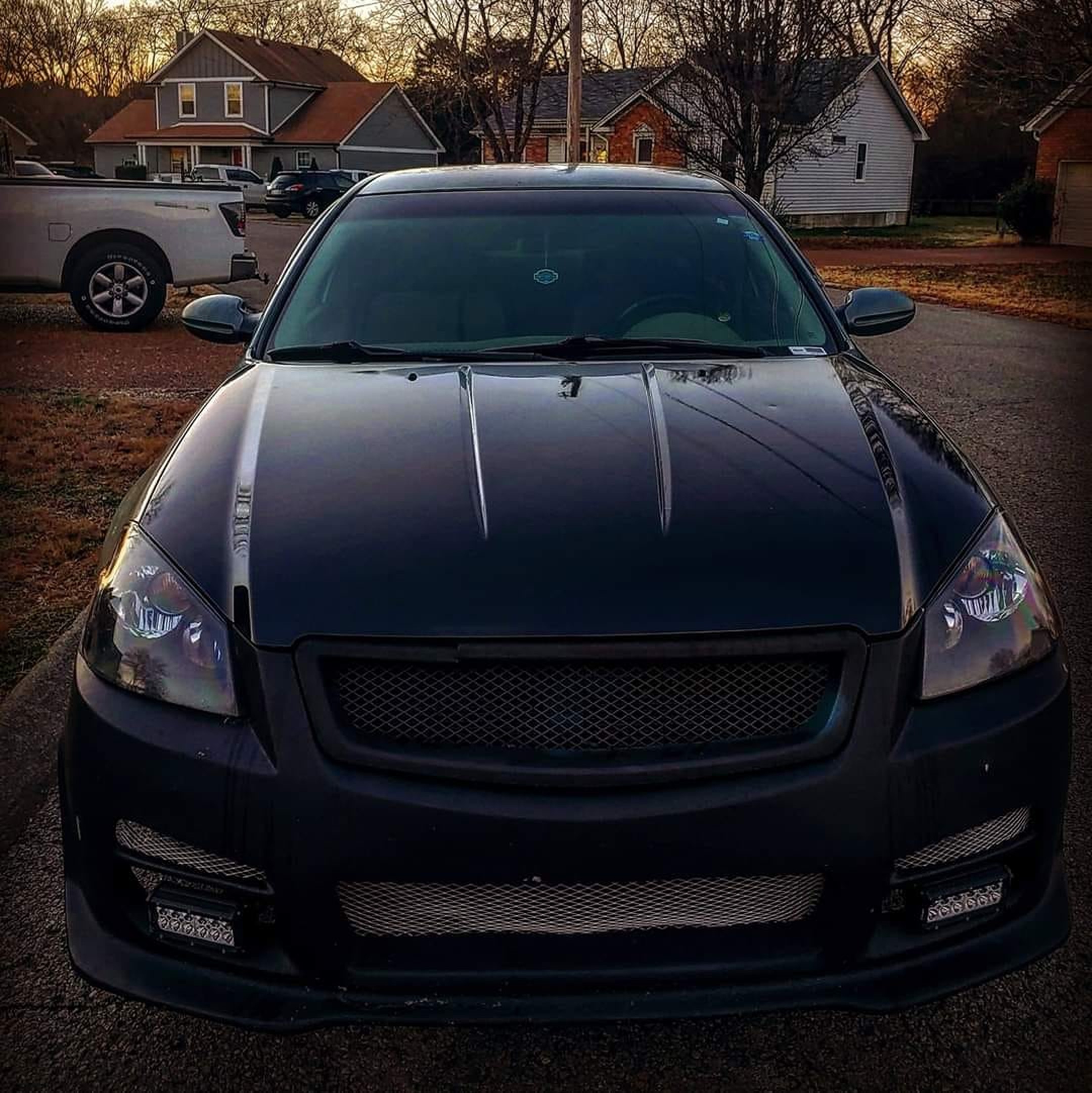
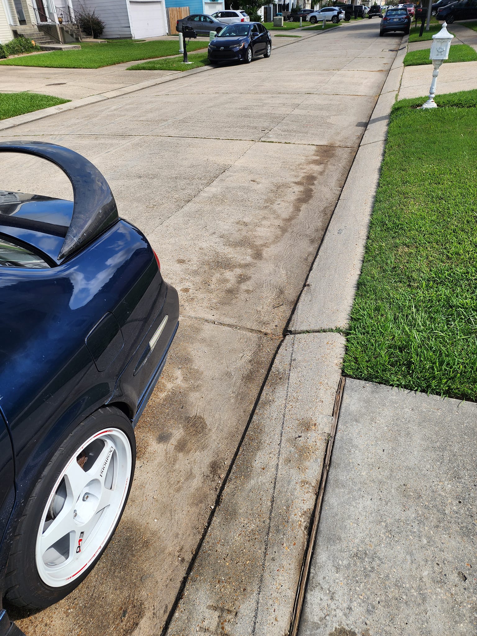
Credit: Shavan Irving
![]()


")
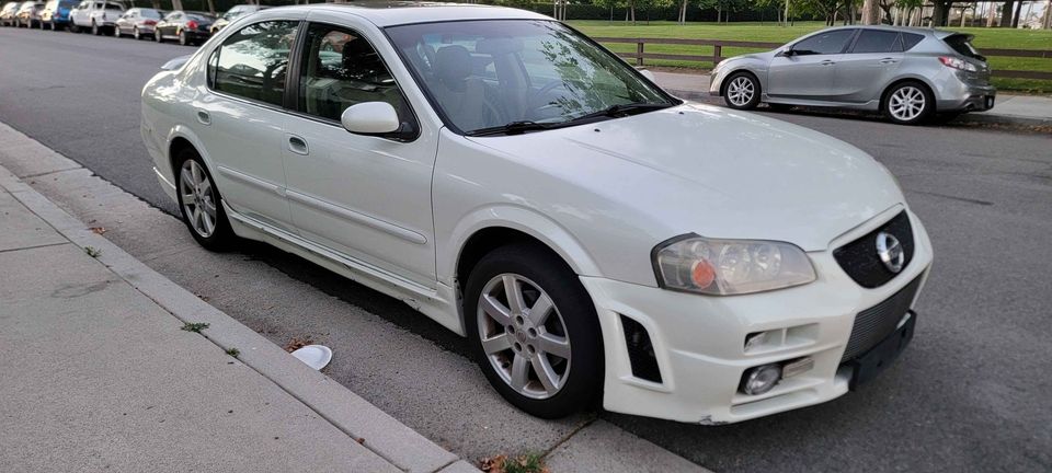
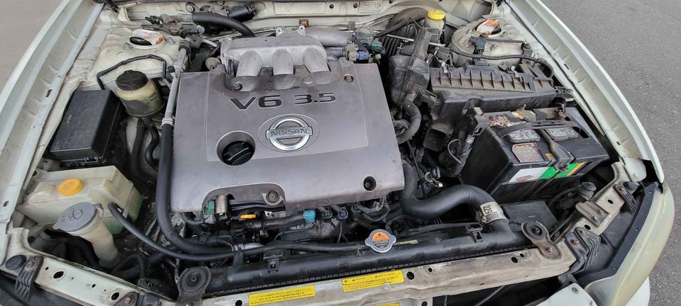
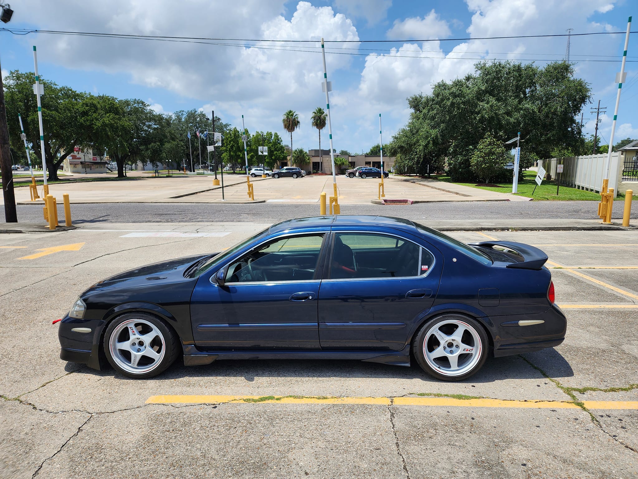
Credit: James Williams
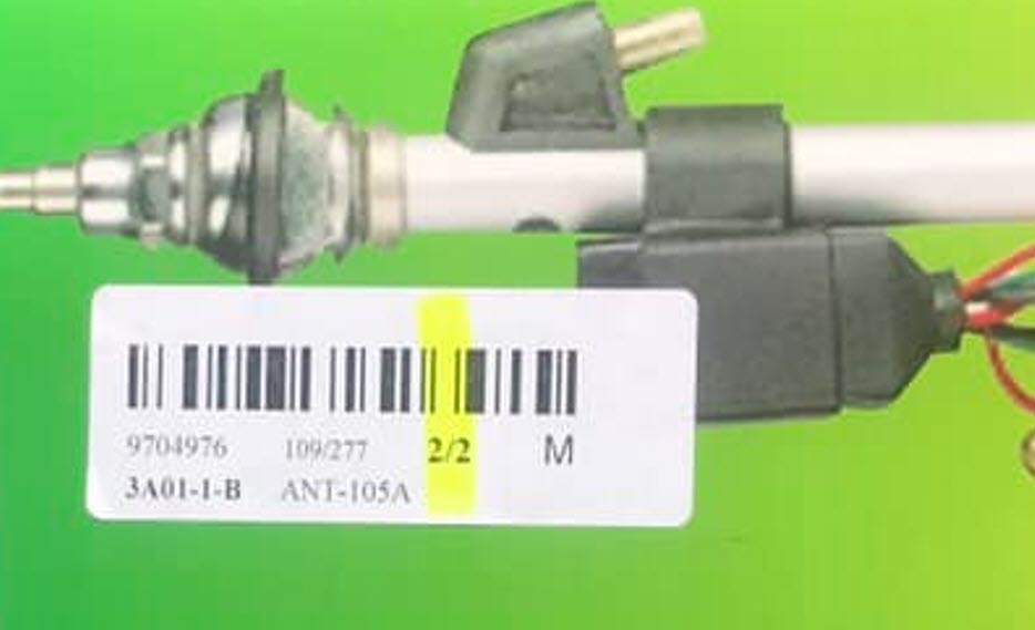
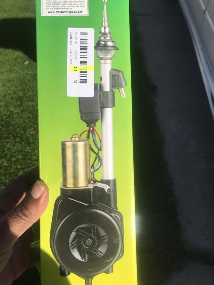
I replaced the power antenna on my 1998 Nissan Maxima GXE, and it works perfectly. The installation took me 30 minutes. I connected red to red, blue to blue, and black to black (ground). I also had to buy a 12-foot antenna cable to reach the stereo.
![]()


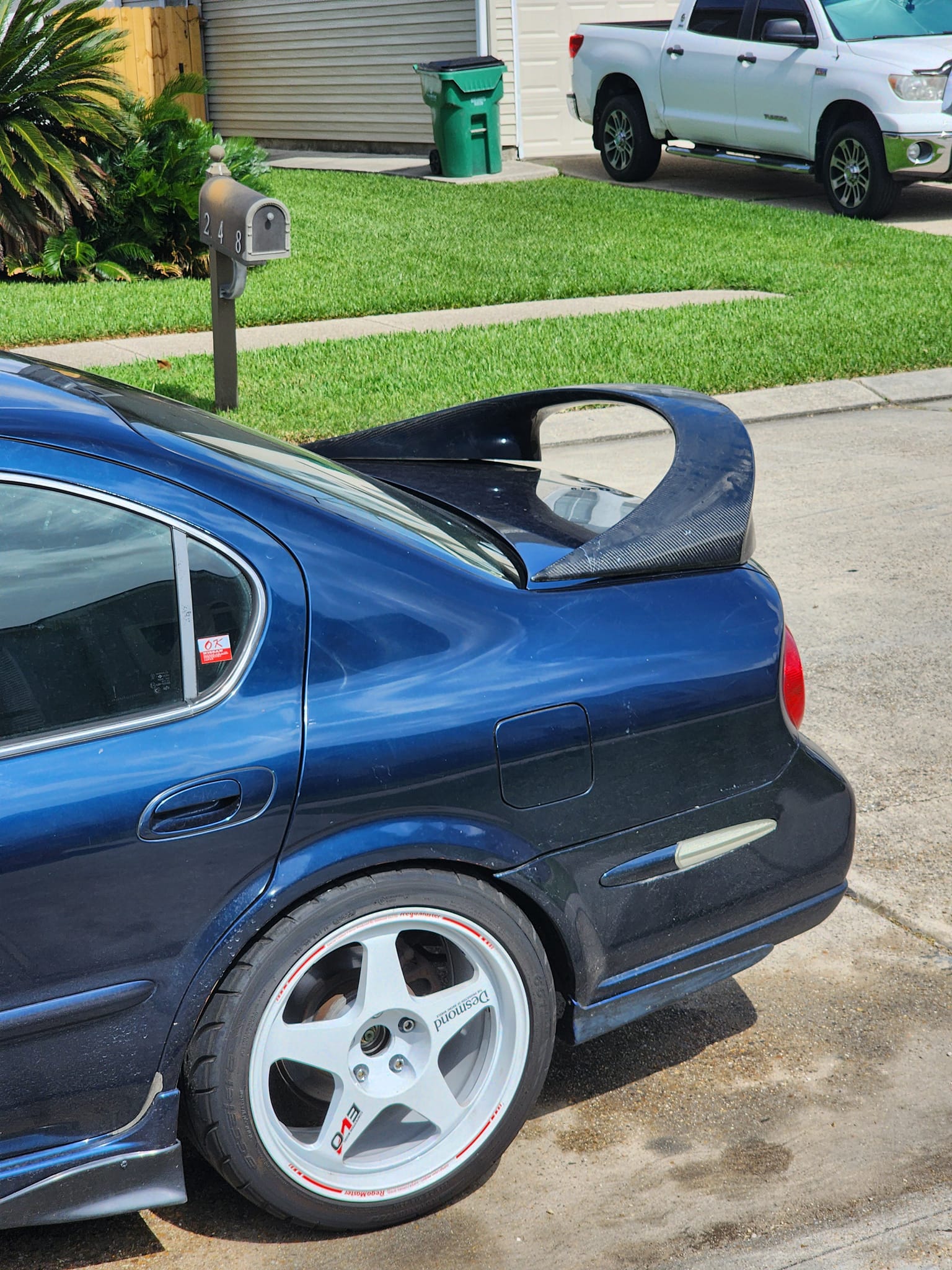
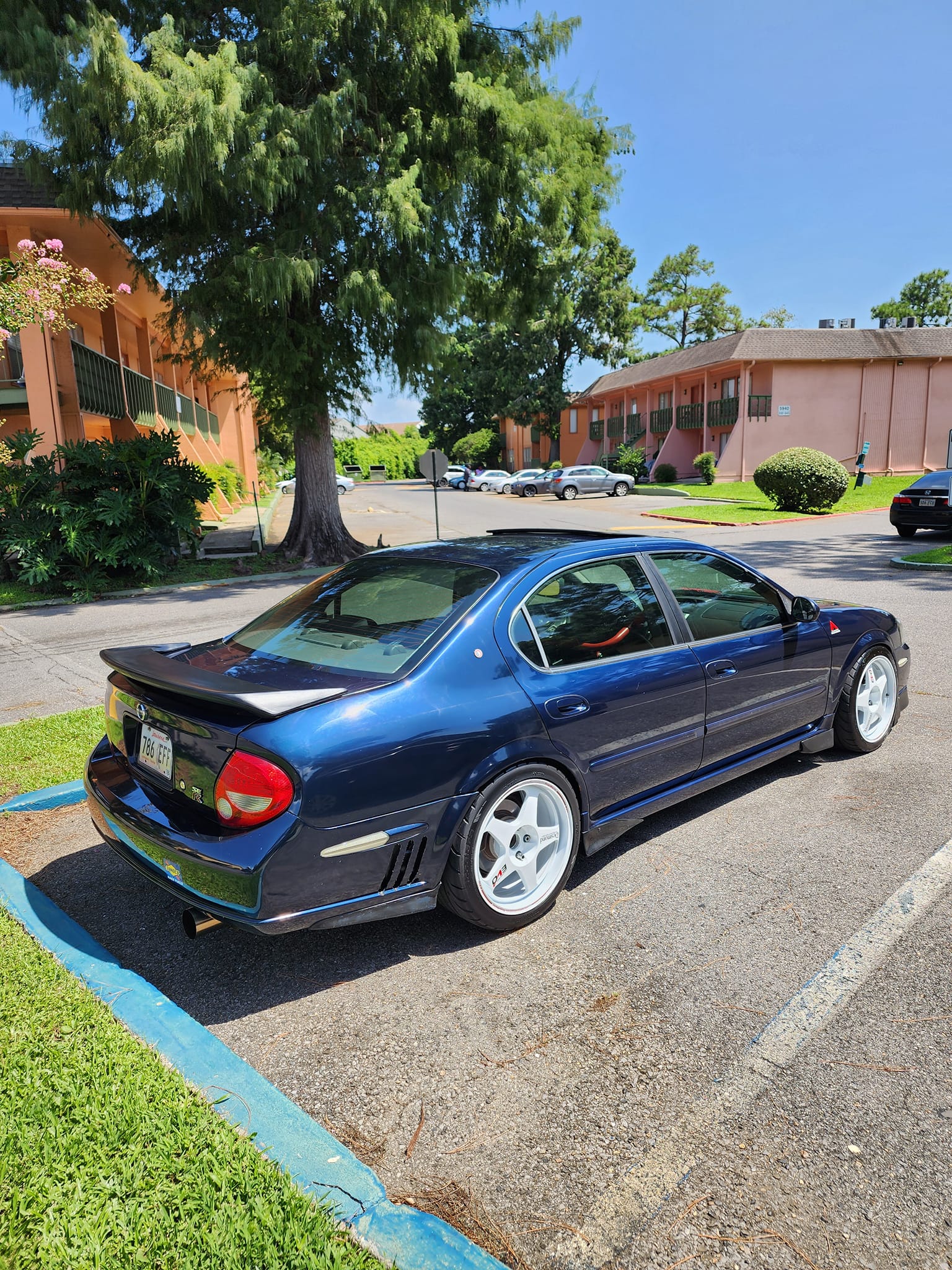
Credit: Apollos2
Order Link: https://www.amazon.com/gp/product/B001DCL31E/ref=wms_ohs_product?th=1
I finally got around to installing the trunk support arms I bought from Amazon. The original equipment manufacturer (OEM) lift was never great, and after adding sound deadening, it barely worked at all.
I purchased the StrongArm 4078 Nissan Maxima Trunk Lift Support, one per pack, and ordered two packs.


This is the trunk in the mid-position—it stays in place now and no longer falls on anyone.

![]()
")
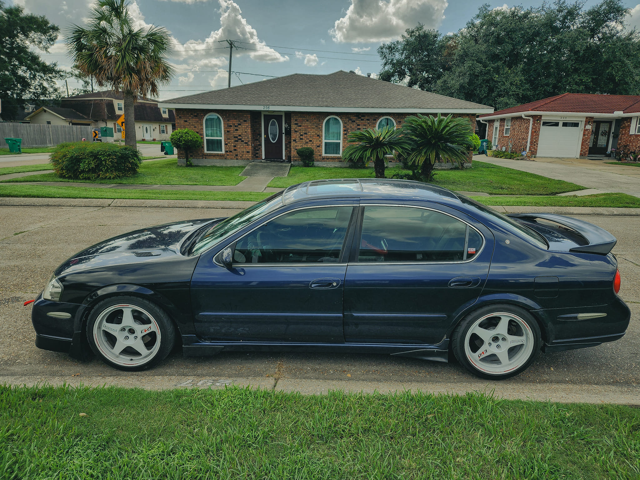
Credit: Mark R.
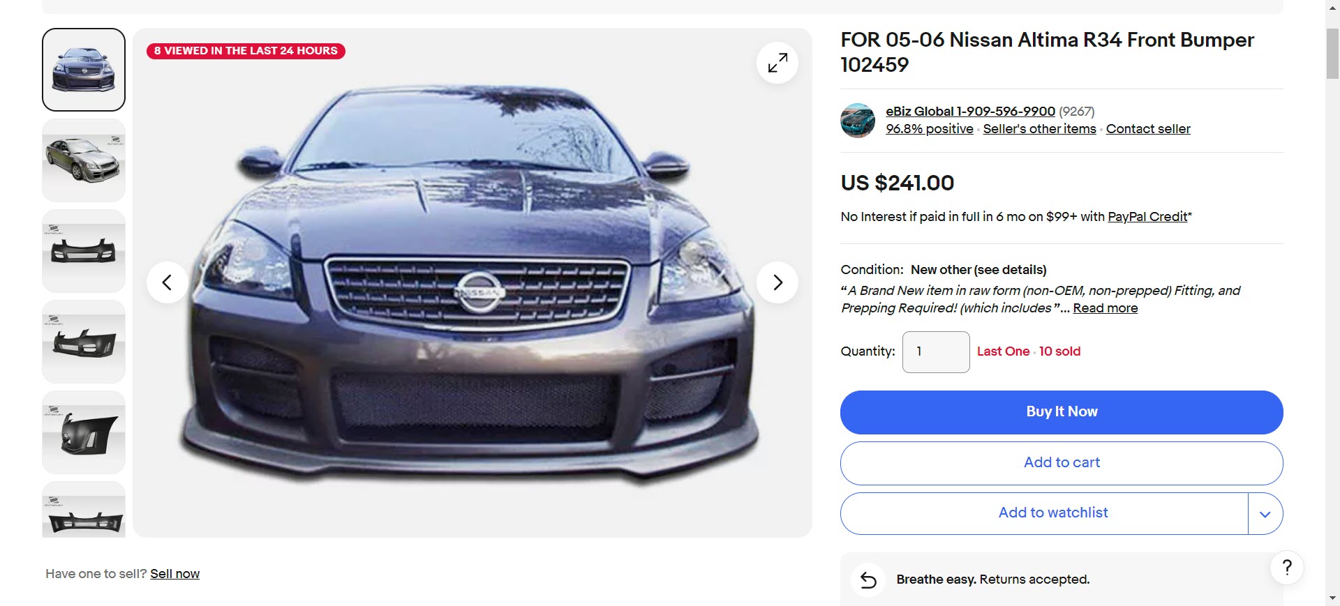
Get your vehicle looking right don’t matter if you’re replacing the bumper, fender or repairing a few dents. Rest easy MBI Auto got you covered in unpainted steel/chrome, primed or even painted to match body panels at prices that nobody can beat.
MBI AUTO OFFERS:
If it not on the website we can source any part OEM or Aftermarket just call: tel: (616) 334-6200 or email: support@mbiauto.com.


![]()
")


Credit: derekg1023
As many of you have shown there is a want for wiring up 3.5SE mirrors to cars that don’t have the wiring for them. I would like to say that I don’t take full credit for this write up.
As with my OEM Steering Wheel Volume Controls write up (http://www.nissanclub.com/forums/f-q-2007/293912-how-install-oem-steering-wheel-volume-controls.html), ruben00 and boystar22 were a huge help. This write up shows how to wire cars with three wires, but can be applied to any car that have 3 or 5 wires, or is fully wired and needs help on removing the mirrors and replacing them.
My way of wiring everything is far less than professional or what ruben00 has laid out for us. I utilize tapping into the driver-side kickplate area for the blinkers and directly connecting the heated (+) wire into the fuse panel. Everything in this method works fine and works as it would OEM, but isn’t as pretty from an installers POV.
Here are the parts you’ll need:
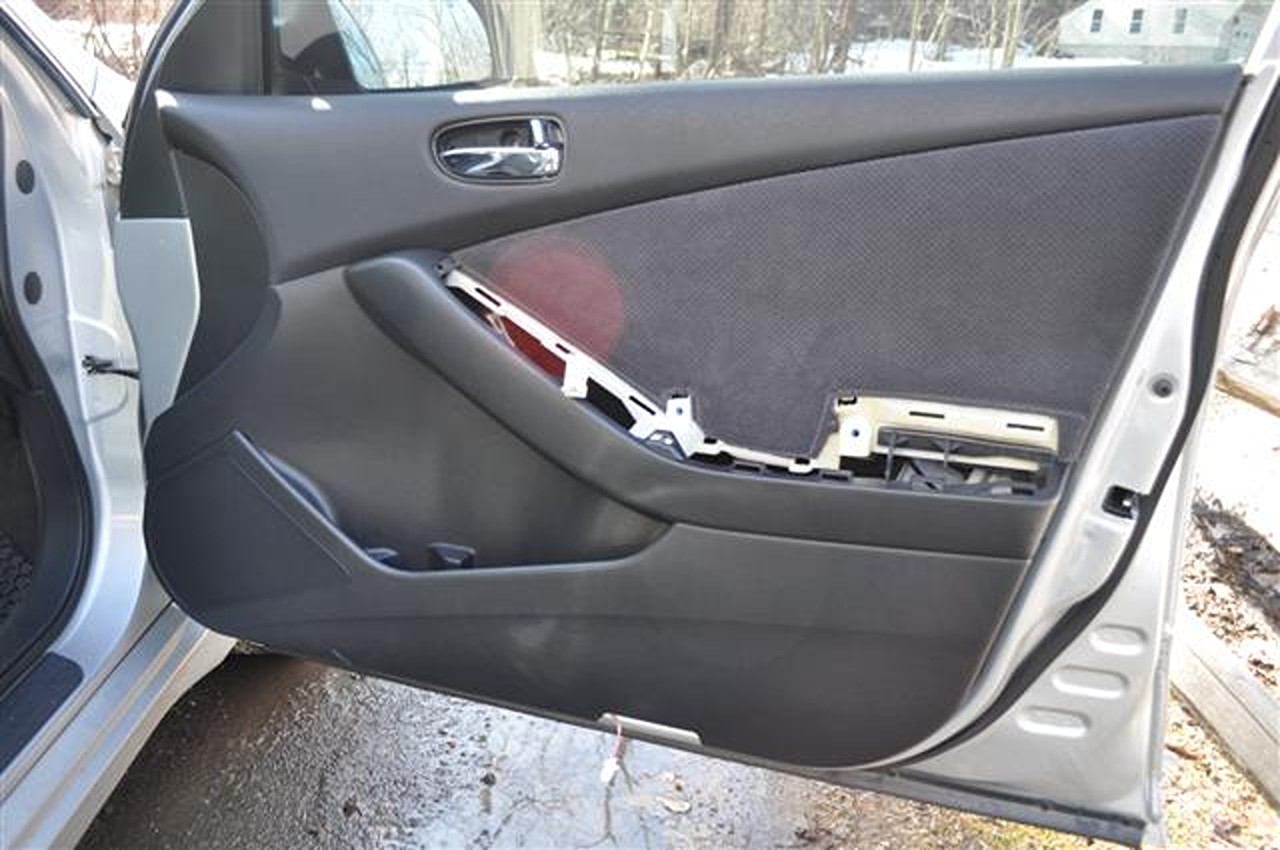
The first step is to remove your door paneling. I recommend starting with the passenger side. You are going to be running all four wires from the passenger side to the driver side of the car so it is best to have those wires ran to the driverside so you can tap all the wires in one whack.
1. Start by removing your arm rest, pull upwards but evenly. The foam is very brittle below so try not to pull up one side with more force.
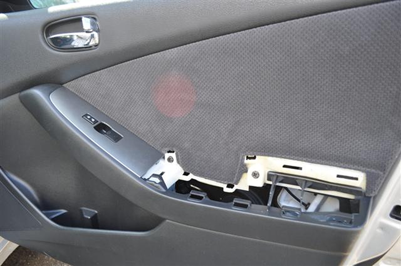
2. Remove your window/door control switch grab from bottom and pull upwards. Disconnect the connectors (3 for driver side, 1 on passenger side) The top connector on the driver side is a pain to remove so you may need a small flat head to push in the release while pulling at the same time.
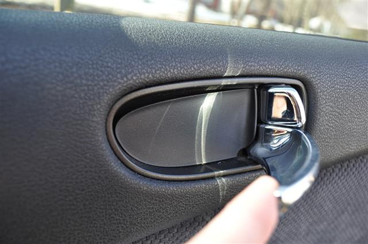
3. Open the handle as shown below and put a screw driver in the bottom right hand corner of the cover to pop it off and reveal a screw.
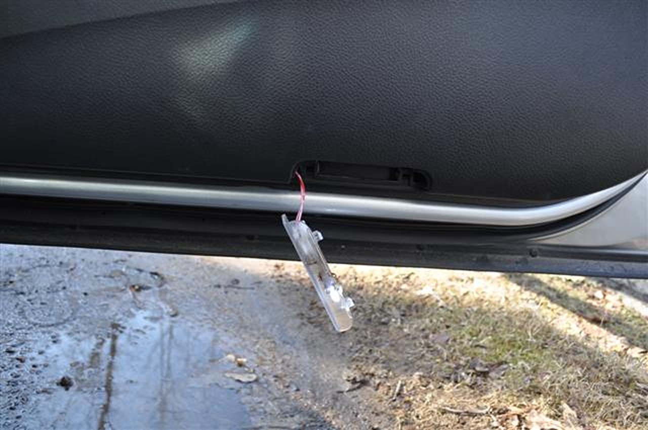
4. Remove the courtesy light by grabbing the bottom and pulling down and out.
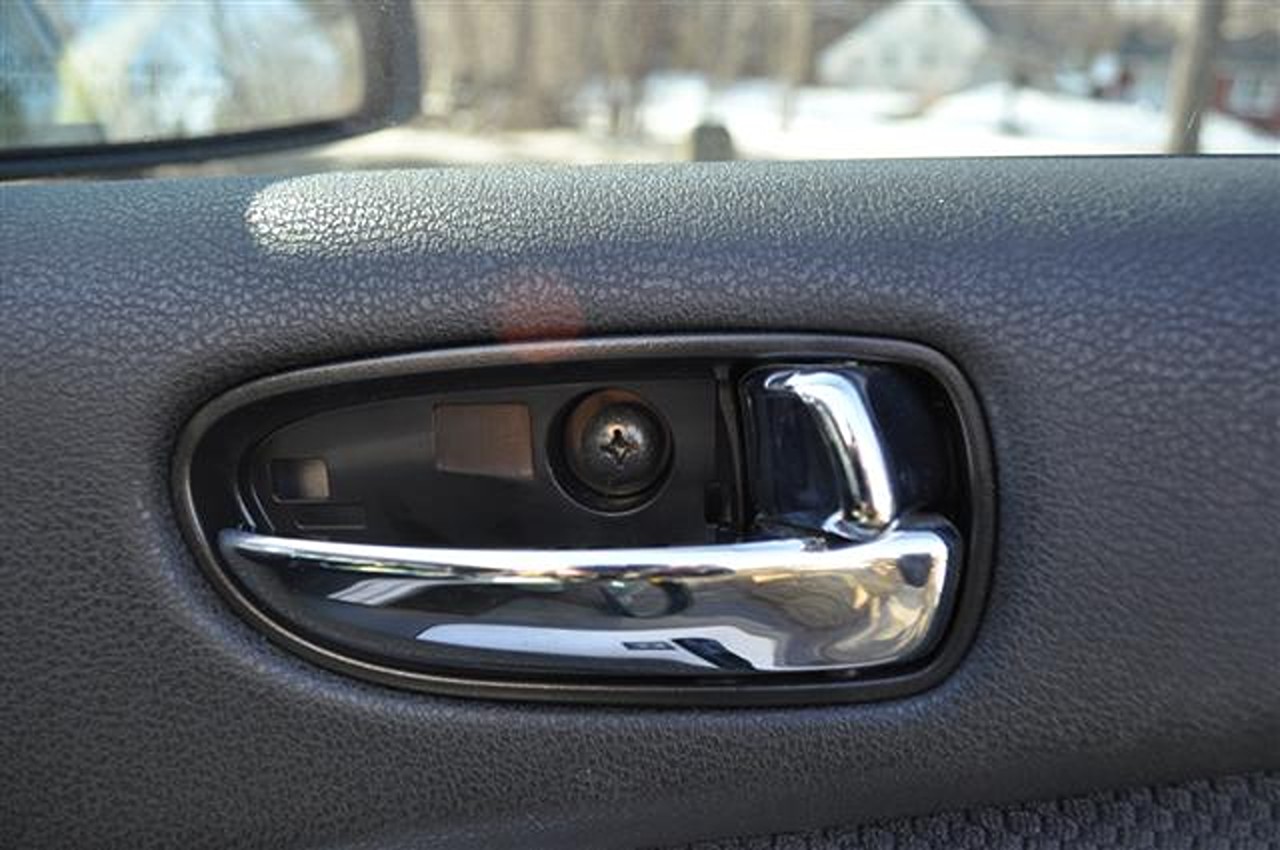
5. Unscrew this screw from beneath the handle.
6. Unscrew the these two screws (utilize a 10mm socket wrench).
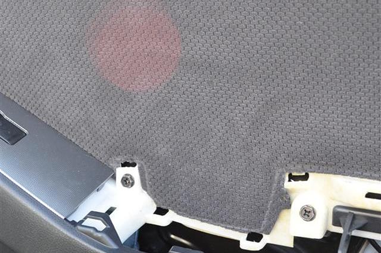
7. With everything unscrewed and all main panels removed. Stick a flat head screw driver in the side of the car with a cloth, this will protect everything underneath the panel, be sure to make sure the screwdriver isn’t going to pierce through the cloth and damage anything by doubling up your cloth.
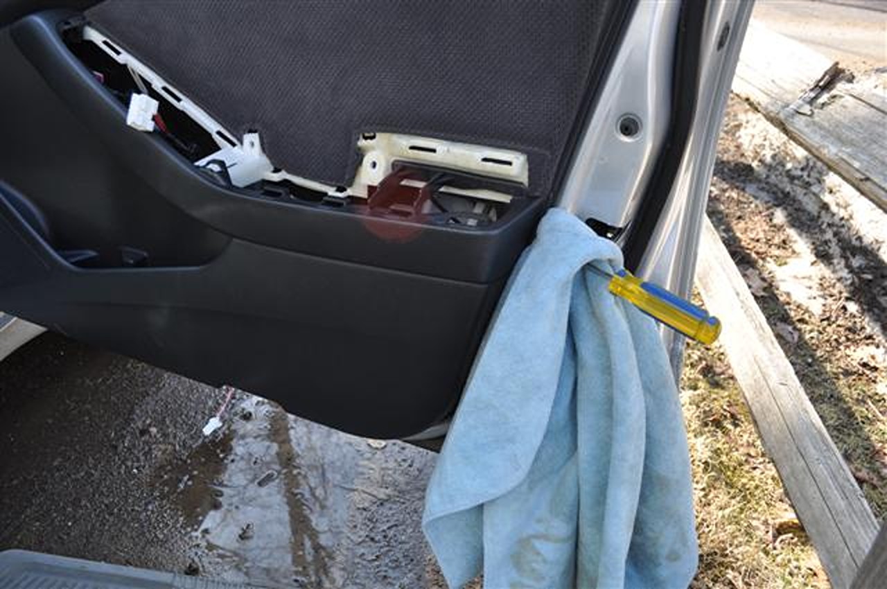
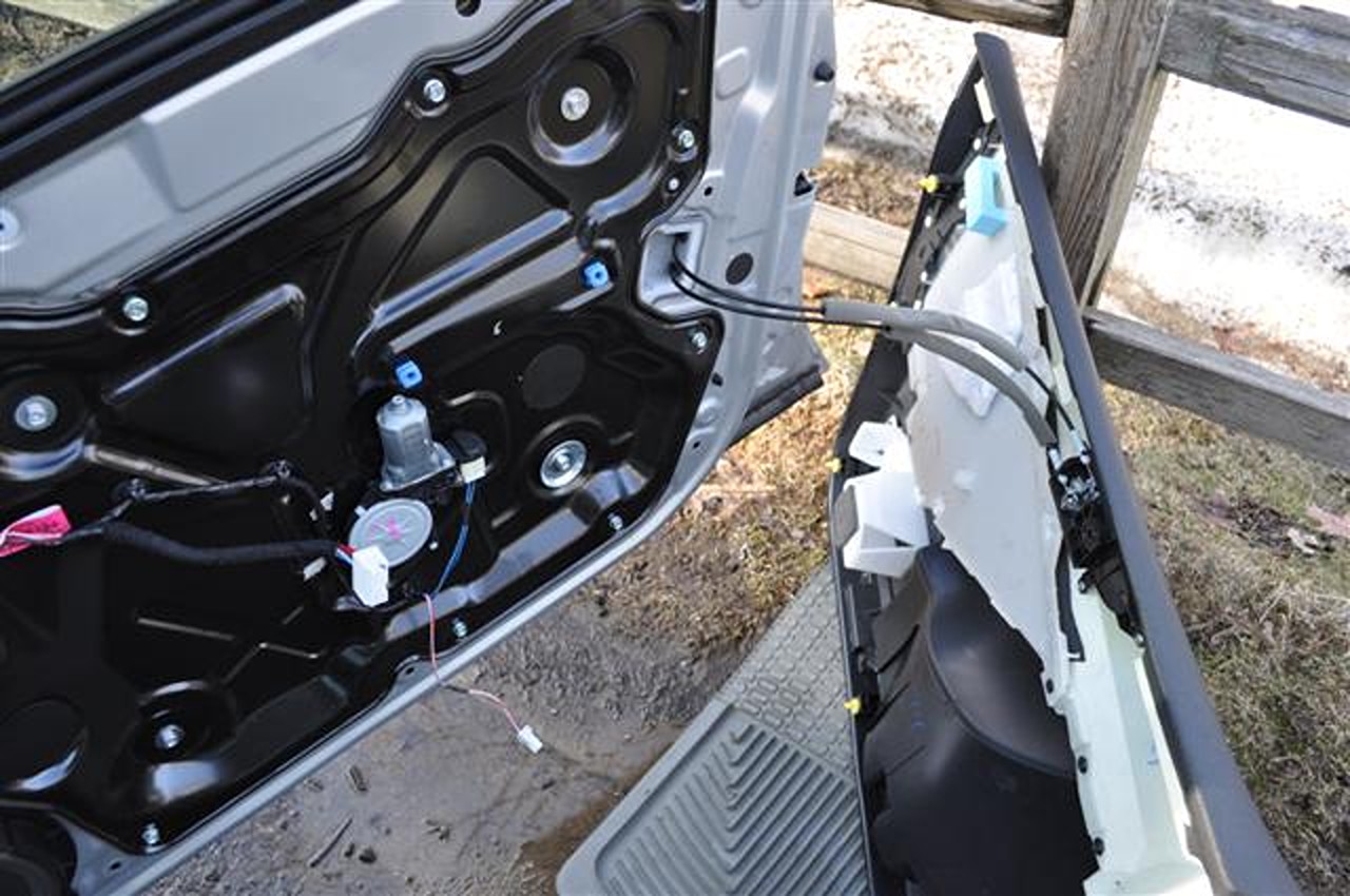
8. Here is what you should now have (notice I put an old car mat underneath the panel to prevent excess scratching to the bottom of the panel).
9. Remove this interior mirror cover. Very simple no real trick to it.
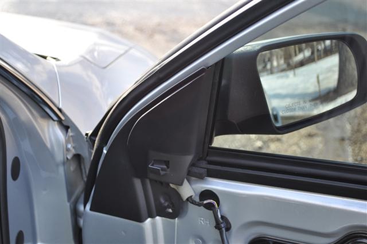
10. Disconnect your connector here by the mirror and remove your mirror to install your new one. Simply unscrew these three screws. They are very very tight. Use a 10mm socket wrench to unscrew.
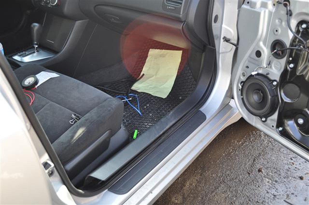
11. Time to start running your four wires, after removing some panels of course… Remove your kick panel as shown below.
12. Remove the upper kick panel. It’s in there real good so you will need to use some force.
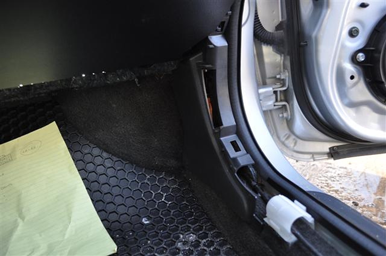
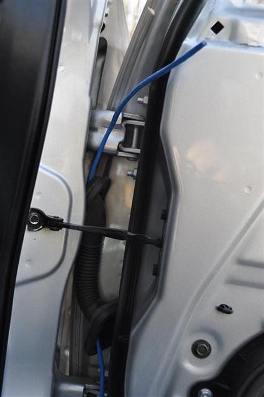
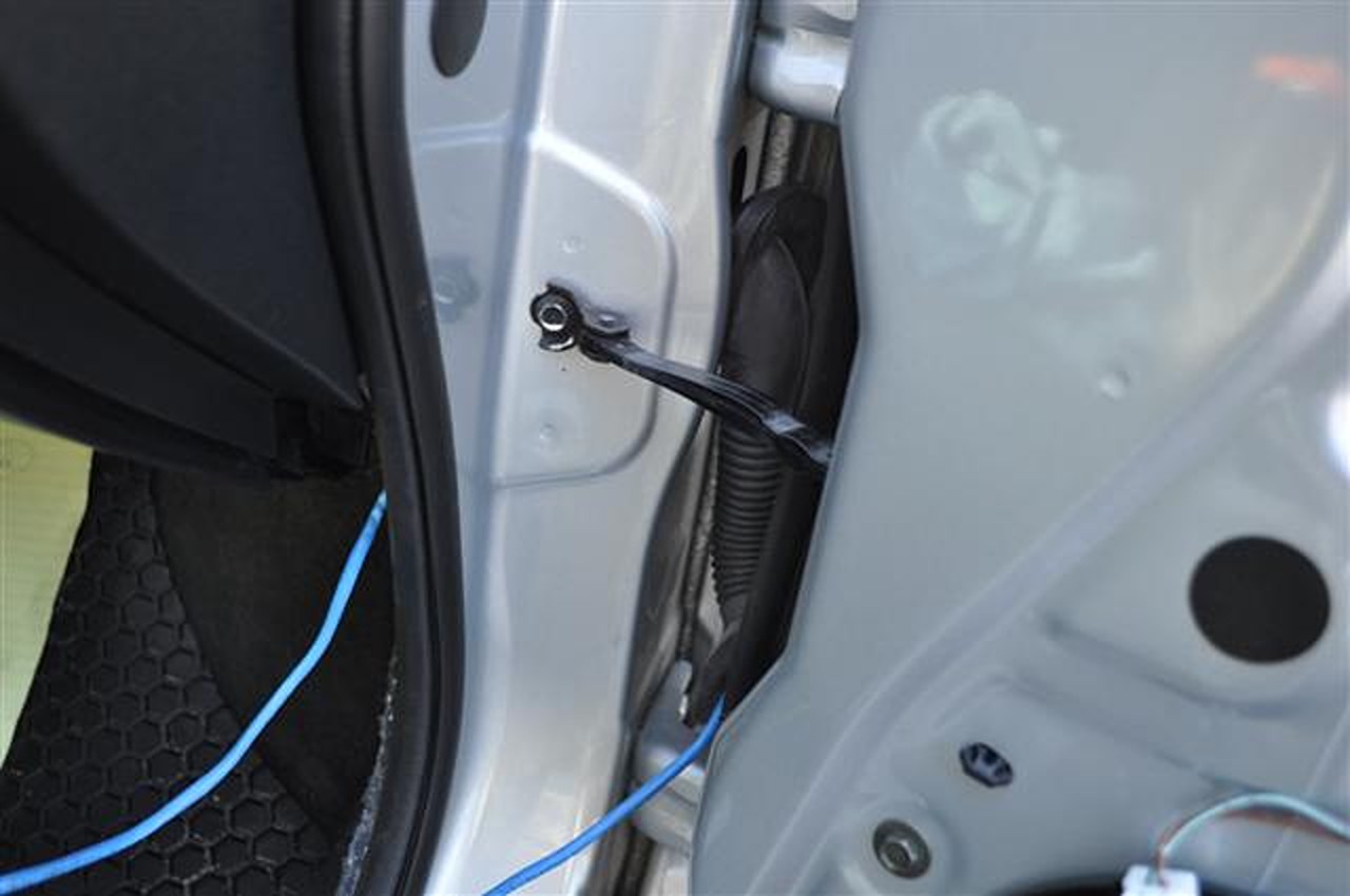
13. Pull out the rubber wire molding from the car and door, you can’t remove this completely as there are wires in it but you will want to have it so it is disconnected. Don’t worry, it’s easy to take off and easy to put back on.
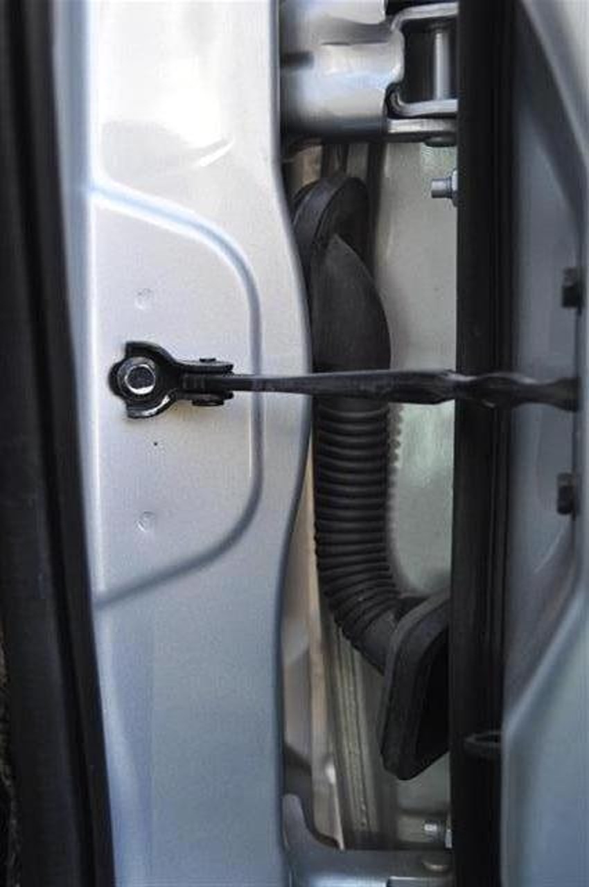
14. To get all four wires through everything I start with a guide wire. Being in the IT field, I utilized an ethernet cord which worked out great. Bring your guide wire to go through the rubber thing (going up works better than down).
15. Bring one end of the wire inside the car now.
16. Now we want to bring the wire into the door. Time to take off the speaker. Disconnect the top harness off it and utilize a 10mm socket wrench again.
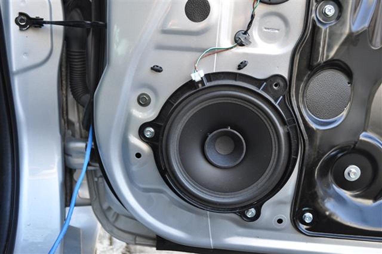
17. Bring your wire inside the door.
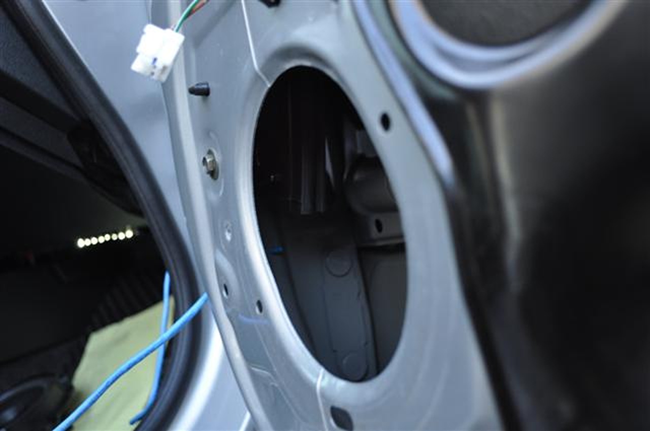
18. Tape your four wires to the end of the guide wire and slowly pull one place at a time until it is in the door.
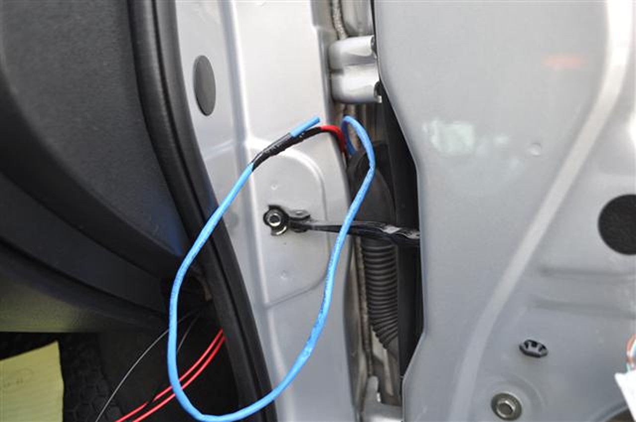
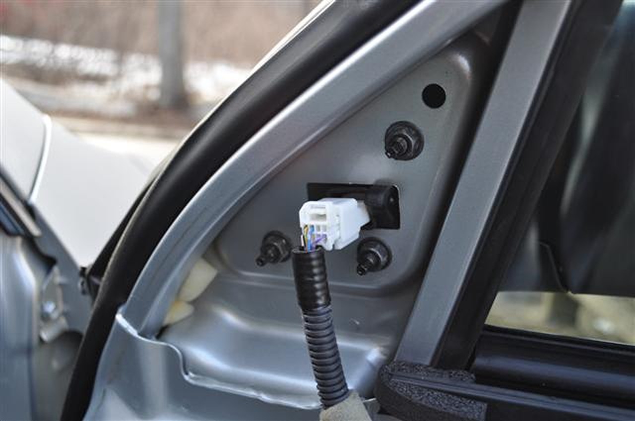
19. When the wire is all ran to the door be sure to give yourself plenty of wire so you will be able to make it to the connector by the mirror while following the same path of the current wires. Zip tie your wires frequently to prevent them from loosening up, etc. Assuming you have followed the path of the existing wire, this is where you’ll end up:
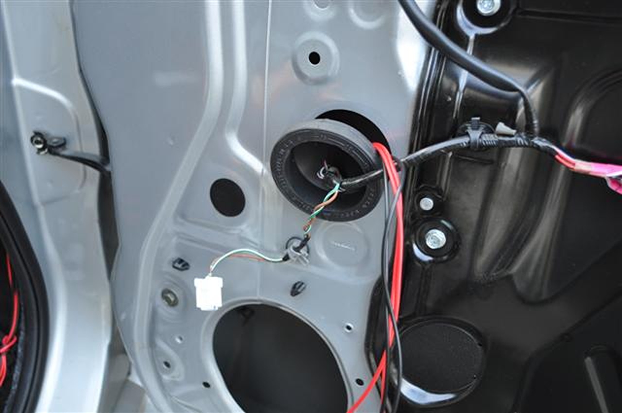
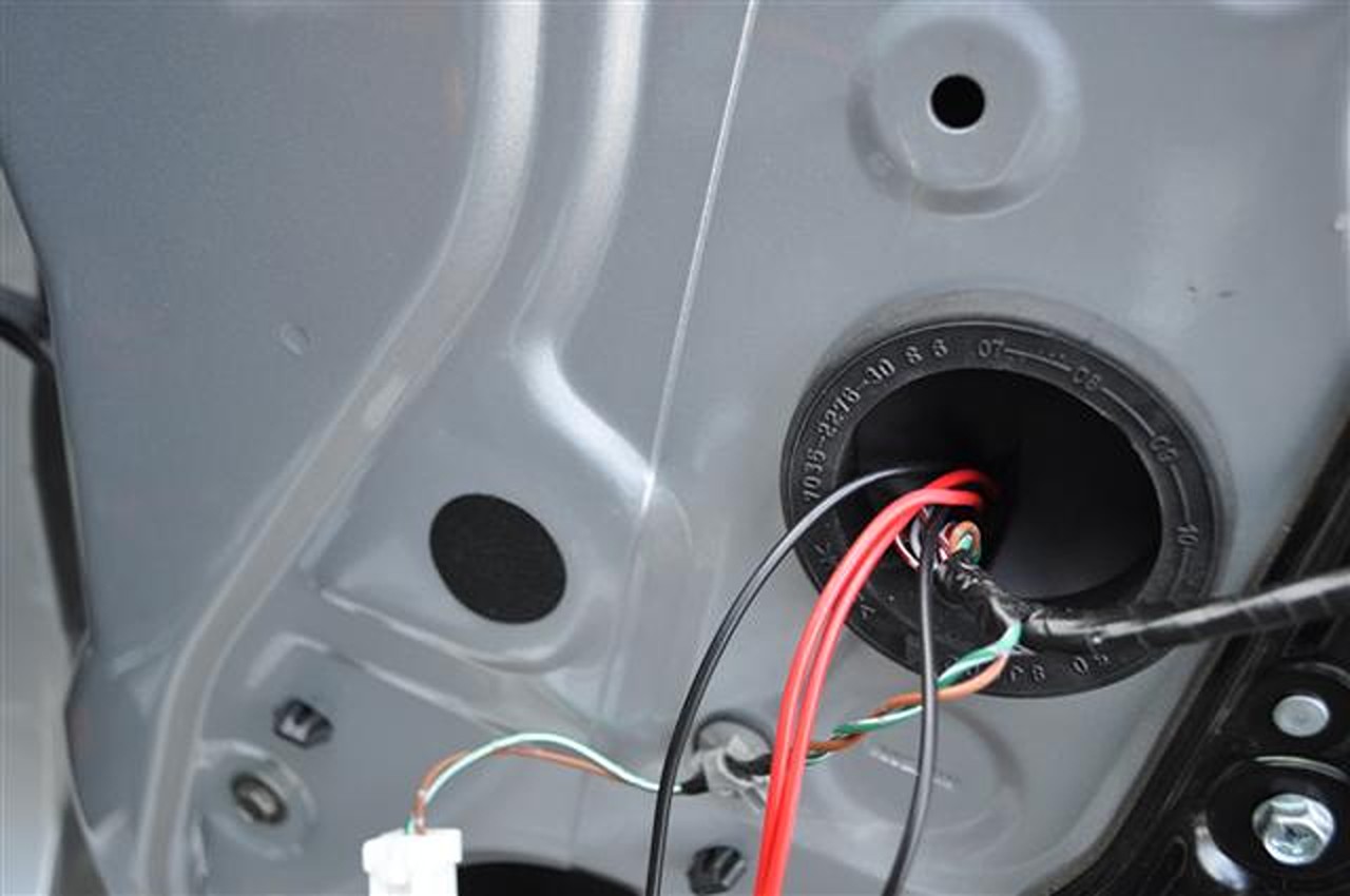
20. Poke a hole through this grommet and run your four wires through it. Again, we are maintaining the same path as the current wires.
21. Now that you have maintained the same path of the other wires tape them together with electrical tape and now you should be at the connector part. Test your wires so you know what pair is going to be for the blinkers and what pair will be for the heat. I utilized the small connector we pulled out that is for the courtesy light at the bottom of the door. Simply put two wires into it and on the other end use a 12v LED to see which wires were turning on the light. This way you aren’t confused about what wires were doing what (in other words, LABEL what wires are the going to what).
22. Time to properly connect your wires in the correct location of the connector. Unfortunately I was unable to track down the same metra harness ruben00 spoke about in his thread so I had to do what boystar22 did. This is sticking in stripped wires into the holes of the connector. This will work. You just need to secure the wires with zip ties and friction tape or electrical tape.
Side note: If you know where to purchase the correct metra harness with the correct pins for inserting in the mirror connector get in contact with me.
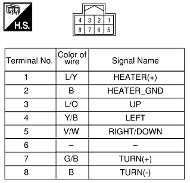
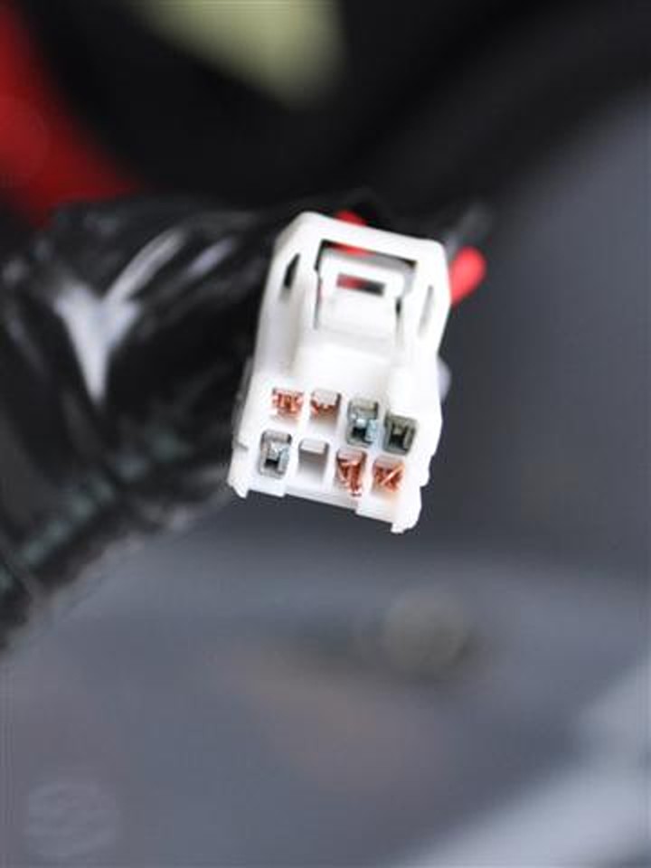
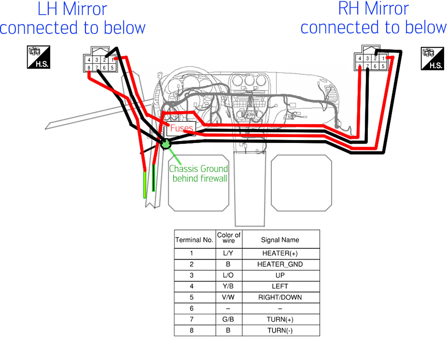
23. Here is the wiring schematic for both sides of the mirror.
24. Here is what my connector looked like in the end. I removed the front cover of the connector which is just a small guide for the pins. Top two are the heat and bottom two are the blinkers.
25. Connect the connector to the mirror. Feel free to test the blinker by connecting the two wires on the opposite end of the mirror to the courtesy light connector to see if it lights up. Pink should be positive and red is ground on the courtesy light connector I believe.
26. Now you will want to run the correct amount of wire from the passenger side to the driver side of the car. I’d recommend removing the kick panel on the left side of the passenger and then just feeding your wires to the driver side through there. Once you have a good guess of about how much wire you’ll need, create four of those wires and put them in a wire loom. Make sure you know what connection goes to what. If you lose track of what two wires do the heat and what two do the blinker you’ll be stuck. Secure your wire loom to anything you want to avoid it draping your feet in the footwells with the loom.
27. Now that your wires are ran, repeat the process for the driverside door. All steps should be the same however you will just run wires to get to the driver side kick plate area.
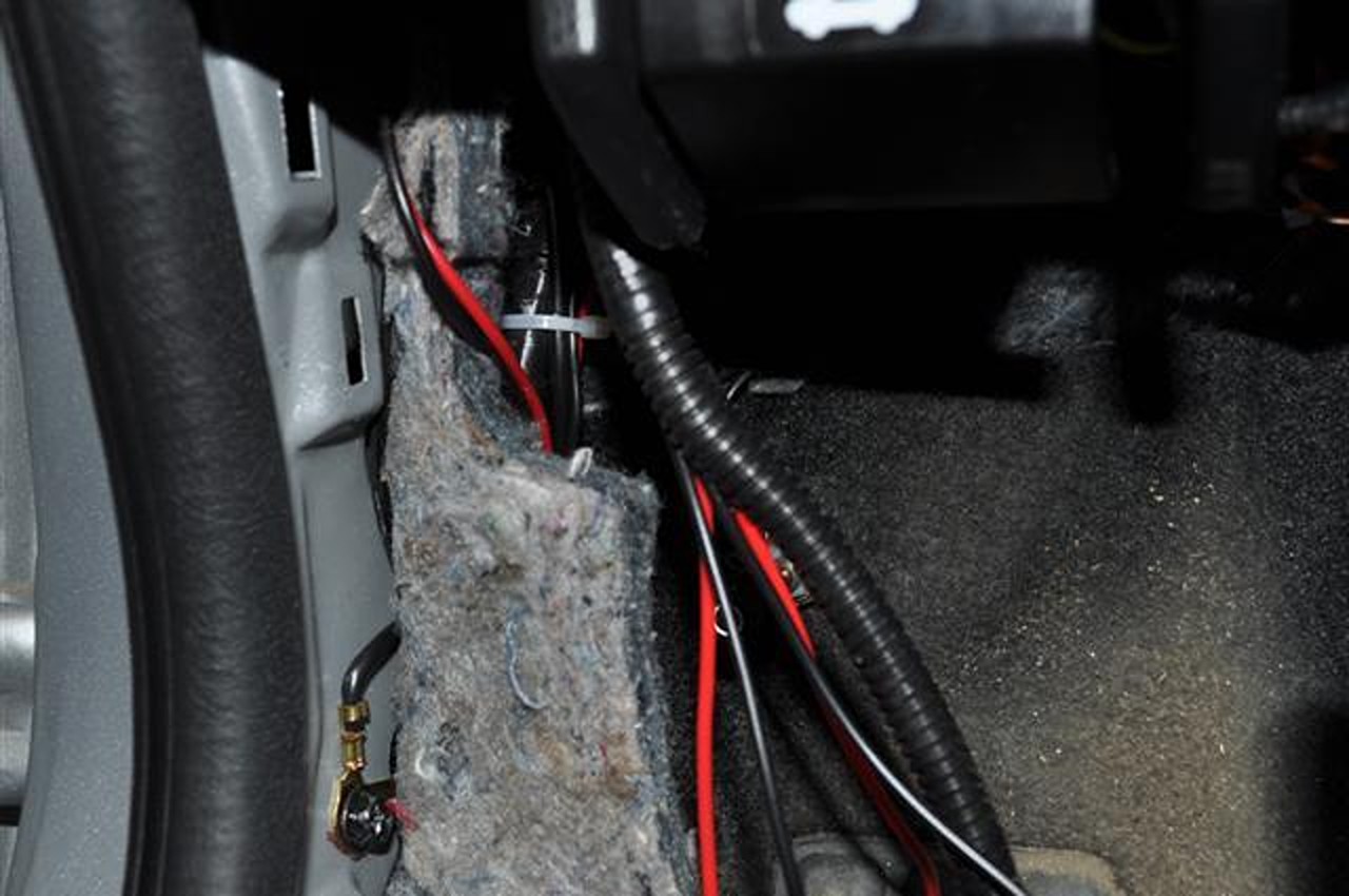
28. Time to hook up the heat, it’s actually the easiest. Grab your two ground wires for the heat. Connect them to the ground hidden behind the firewall. Loosen this bolt with a 10mm socket wrench.
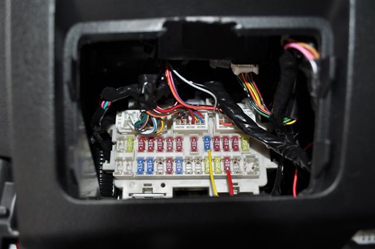
29. Take your two positive wires and connect them into this location of the fuse panel. It is labeled as heated mirror on the back of the fuse guide on the cover to the fuses as well. What I did was connect a small 3in red wire to this location which branched off into two connections that I heat shrunk together. If you can’t tell, this location is at the way bottom and at the 2nd position from the right. Ignore the slew of other wires you see in there. I have a remote start installed.
30. Feel free to test your heat, if it’s not working after turning your car on and pressing the button for the rear windshield then check over your connections at the mirror. Since we didn’t use pins that are inserted perfectly these are the connections that will fail. Also, be sure you connected the correct wires and that your fuse is okay.
31. Blinker time. Here are the wire colors that are utilized for the blinkers:
Same location you connected the heated ground wires = Ground for Left & Right
Green with Yellow Stripe (lesser thick gauged one) = Left (+)
Green with Black Stripe (lesser thick gauged one) = Right (+)
Tap the connections with a T-Tap connector.
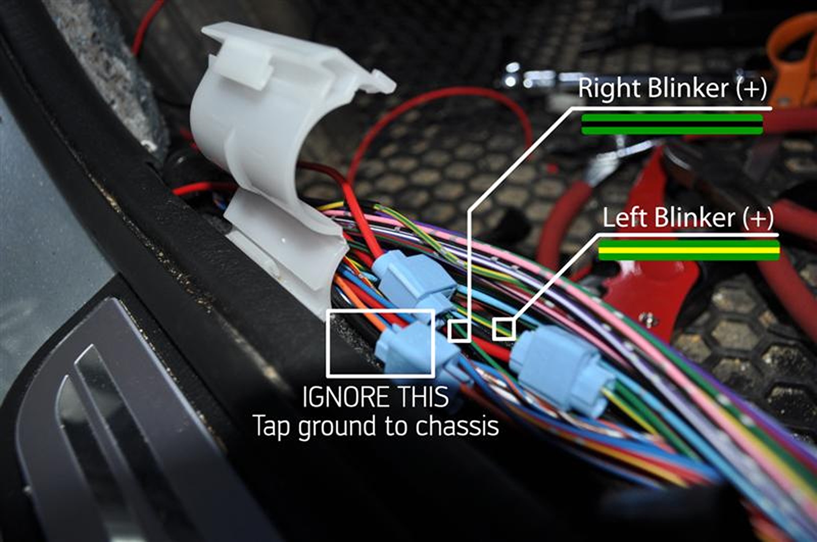
Original photo so there is no mistaking what wires to tap.
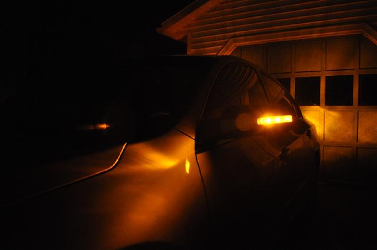
32. Test all connections to make sure everything works. Push the hazards button to test both at the same time and turn the car on and press the rear wind shield button to test the heat. You’ll be able to tell after a few minutes if the mirrors are warm to touch.
33. The last thing to do is button it all up. Follow steps 1-10 backwards and enjoy your car with mirrors that are heated, have blinkers, and can manually turn in!
Crude Graphical Reference of Location of Wires:
This is my third “How To” on the forums and all the images are hosted on my own hosting package so donations are appreciated!
As always I, nor do any of the people who posted guides or advice take any responsibility for your car, assets, or anything else in the event that something goes wrong with anything you do after reading our threads.
-Derek
![]()