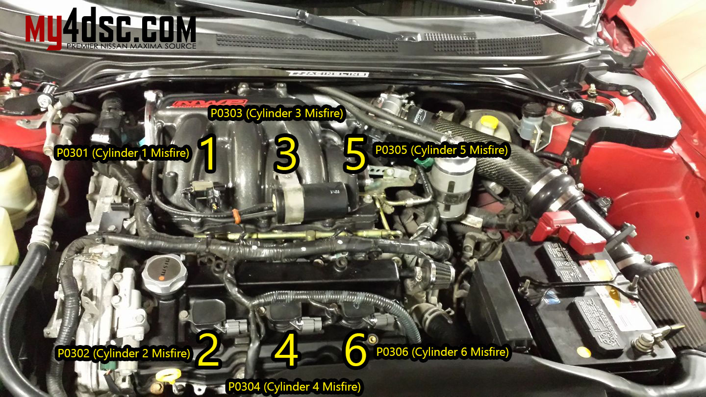
This article shows how to swap a 2007+ Altima 3.5L VQ35 engine, or 2009+ Maxima 3.5L engine into older Nissan Maxima’s. Including the 2002-2006 Altima (3.5L) and 2002-2008 Maxima’s. This motor swap is referred to as the 2nd Generation (Gen2/Gen3) VQ35DE swap.
NISformance Swap Kit
This kit allows you to install a 2nd generation or 3rd generation VQ35DE engine into a 2002-2008 Maxima or 2002-2006 Altima (3.5 V6)
The NISformance 2nd Generation VQ35DE swap kit consist of four main components. (2) Cam sensor signal inverters, a plug and play throttle body adapter harness, a belt tensioner bracket, and an alternator bracket. Each component and its intended use is detailed below.
Camshaft sensor signal inverters – Allow the stock harness to be attached to a newer 2nd generation motor and intercept the camshaft signal wires. This is an essential part of the swap kit and has been designed with ease of install in mind. Each inverter comes with a camshaft sensor plug attached. Wiring necessary consist of three wires. Ground, Power, and Signal. These new inverters are single channel. One inverter is required for each camshaft position sensor.
Throttle body adapter harness – Necessary in order to utilize the 70 or 75 millimeter throttle body that is equipped on 2nd generation motors.
Belt tensioner and alternator brackets – Needed in order to use stock alternator and belt tensioner. Zinc coated for high corrosion resistance and added clean look.
VQ35DE Engine
There are three generations of the front wheel drive VQ35DE engine.
The first generation VQ35DE was used by Nissan in many front wheel drive applications. Ranging from the Maxima to the Quest minivan.
Second generation engines were used in the 2009+ Maxima , and 2007+ 3.5L Altima as well as a few other front wheel drive applications as before. The second generation VQ35DE engine is equipped with “HR” heads allowing for increased air flow and improved performance. Oil consumption and other flaws commonly found in first generation motors have also been addressed.
There are also two variations of the 2nd Gen VQ35DE engine. A Maxima engine is equipped with EVT ( Exhaust Valve Timing ) and has a slightly higher compression ratio along with larger intake manifold and throttle body (75mm). The Altima engine has a slightly lower compression ratio, and is not equipped with EVT. The intake manifold and throttle body (70mm) are also a bit smaller.
There is now a third generation of the front wheel drive VQ35DE. This engine is found mostly in the 2016+ Nissan Maxima. This engine can be used for this swap, with the only difference being the TB pin out. We offer the correct TB adapter harness for this newer TB as an option for our swap kit.
There are a few things to keep in mind before beginning your swap:
It’s easier to do this swap if you have a 3.5 DE motor laying around, especially if you just pulled it out of the car. You will need to take some things off of the old motor to use on the HR. Without this, there are a few parts that you will have to purchase in order to complete the swap.
Keep in mind, you are swapping the “long block” with intake manifold only. You will need to re use a lot of your existing accessories or parts specific to your car. This also includes wiring and harnesses, sub harnesses ect..
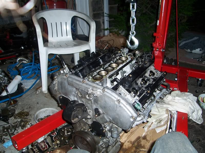
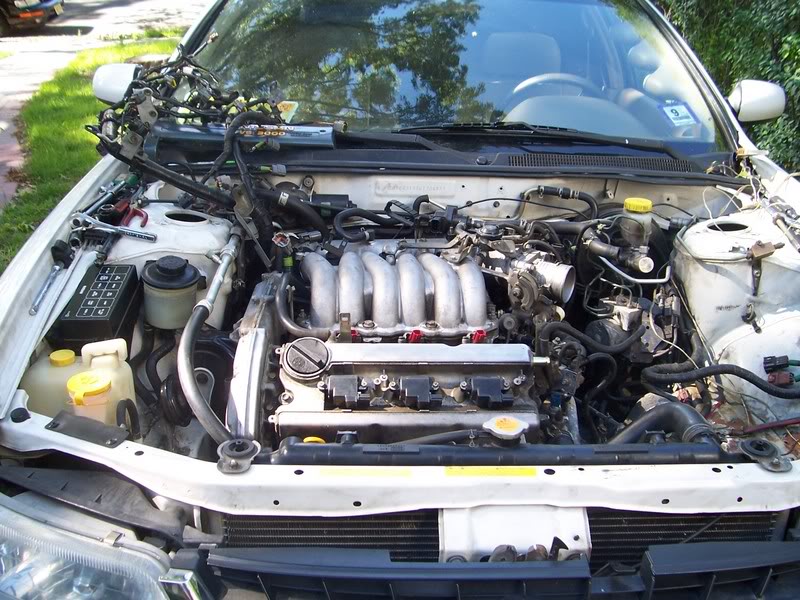
Picture below is what your prepped “2nd Gen” or “3rd Gen” engine should look like prior to going into your car.
There are some specific tools needed: An ‘E8’ torx socket, 5/16 Allen key, Loctite
Stripping the motor
Depending on where your motor came from, there may be a lot of ‘extra’ pieces still attached to it. Some of these will just get in your way while you prep your motor, some can’t be used for this swap.
Remove all accessories, which includes the alternator, power steering pump.
Remove any harnesses and brackets that are still connected to the motor.
Remove upper intake manifold (removing lower manifold is not necessary, but sometimes desirable. If removed, a new gasket should be used to reinstall).
Remove oil temperature sender:
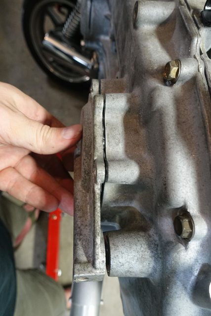
Remove idler pulley/tensioner ‘spacer’ (seen below in red): ** The injector rail may also be removed, but that isn’t necessary.
Modifying the Motor
Some parts of the motor will need to be cut somehow (tools, methods and results will vary) to allow for proper fitment and function once it’s reinstalled.
** Because of some concerns about the integrity of the stock oil gallery gasket, we at NISformance strongly recommend replacing it in this step. **
When changing the oil gallery gasket, this is a good time to grind away the center portion of the power steering bracket before reassembling the front of the motor.
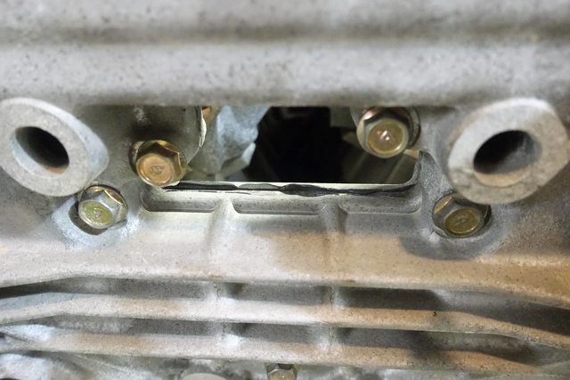
Grind/cut away the center portion of the power steering bracket. This requires some aggressive cutting, but also needs some attention to detail (cutting too DEEPLY can weaken the integrity of the timing cover. Cutting too WIDE can weaken the remaining brackets that will be needed to hold the alternator):
Grind/cut away a portion of the metal where the idler pulley/tensioner spacer was:
Remove exhaust manifold studs at the rear most exhaust port (close to the trans). This requires an ‘E8‘ torx socket:
Clean out the threads in the opposite holes using a ‘10×1.25‘ tap.
Replace the removed studs into the newly cleaned holes:
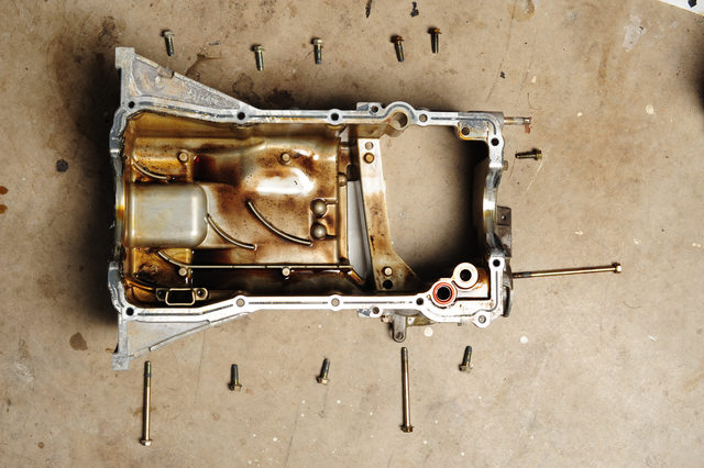
Remove lower oil pan.
Remove upper oil pan.
Use the oil pan from a 3.5 DE motor…but remove the windage tray. Add your o-rings and seals, and install upper oil pan onto the HR motor.
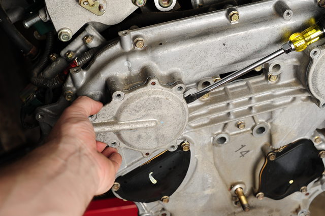
Remove the HR water pump access cover, and replace it with the one from the DE motor
Alternator bracket
Belt tensioner bracket
Adjusting the Cam Signal Trigger Wheel
*Please note that we now offer a completely bolt on trigger wheel that eliminates the need to modify your stock trigger wheels*
If you choose to modify your stock trigger wheels, please note that this is a VERY important step and it must be done very carefully for your car to run properly. You have to be extremely accurate.
Apart from the wiring, adjusting the signal wheel is the most detailed work you need to do on the swap. It is important to be very accurate when cutting or grinding, and it’s also extremely important to assemble everything correctly at the end of this step. Pay close attention to the pictures and make sure that your work looks EXACTLY the same!
*You will need to modify your 5/16 Allen key by cutting the arm down so that it is approximately 3/8″ long. This is your ‘special tool’ that you will need to use in this part of the swap.
Open one of the valve covers.
Using the ‘special tool’, loosen the signal wheel lock nut and remove the signal wheel from the intake cam:
Completely remove the inner nubs from the signal wheel without damaging the rest of the inner surface:
Add Loctite to the flat inner surface of the signal wheel:
Reconnect the modified signal wheel to the intake cam…be sure to place it at the proper angle (as shown below) and resecure the lock nut:
Close and bolt down the valve cover
Open the other valve cover, and repeat these same steps.
V2 Cam Sensor Signal Inverter Wiring
V2 inverters are single channel. One inverter is required for each camshaft position sensor.
Wiring for cam sensor signal inverter
Red wire – 12 volt power supply ( power going into the board )
Black wire – Ground
Orange wire – Signal out ( connects to existing wire on ecu side )
Picture below demonstrates the older style DE cam sensor plug that is cut off when wiring in inverter with required wiring
V1 Cam Sensor Signal Inverter Wiring
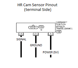
The wiring harness in your car needs to be connected to the newer motor, and it’s not just a ‘plug-and-play’ situation. These diagrams show you the changes that need to be made to make your DE harness control your HR motor:
** THESE WIRE CONNECTIONS ARE CRITICAL. MAKE SURE THAT THEY ARE CONNECTED CORRECTLY (ACCORDING TO THE INSTRUCTIONS), AND SECURELY. TWISTING THEM TOGETHER IS NOT GOOD ENOUGH. **
The stock cam signal wire will be intercepted (cut) by the cam signal inverter supplied with the swap kit. There are six wires on the cam signal inverter…here’s how you connect them:
the RED wire goes to a 5v source from your car’s harness (to supply power to the sensor)
the BLACK wire is ground
For Cam #1…cut the existing wire:
the YELLOW inverter wire connects to the existing wire on the CAM side
the ORANGE inverter wire connects to the existing wire on the ECU side
For Cam #2…cut the existing wire:
the BLUE inverter wire connects to the existing wire on the CAM side
the GREEN inverter wire connects to the existing wire on the ECU side
This section is for documenting the top lists of verified Nissan Maxima & Altima 1/4 mile track times. All numbers were verified with dyno sheets. These are big accomplishments in the community showcasing the potential of these cars.
Important Note: This list is meant to serve as a reference and motivation purpose vs “who is better and who is faster”.
This section is for documenting a list of verified Nissan Maxima, Altima & Sentra Horsepower (HP) dyno numbers. All numbers were verified with dyno sheets. These are big accomplishments in the community showcasing the potential of these cars.
Important Note: This list is meant to serve as a reference and motivation purpose vs “who is better and who is faster”.
Community Member Credit: Tavarish aka Freddy (nycmaximas)
Tools Required:
1/2″ Ratchet
1/2″ Breaker Bar
1/2″ Torque Wrench
3/8″ Ratchet
8mm-24mm Hex Keys (assorted sizes)
32mm Impact Socket (1/2″ drive)
Power rotary tool (Dremel) w/ cutting/grinding bits
1.5 Ton Hydraulic Jack / Lift
Jack Stands
2002-2007 Nissan VQ35DE Engine
Cam Timing Adapters
Getting started
So you’re ready to get rid of that old outdated 3.0 and put in a brand spanking new low mileage VQ35DE? You’ll have to get a few things before you start the swap.
Tools – I suggest about 2-3 sets. With tools scattered around everywhere, and possibly 2 people working on the car, tools have a tendency to disappear. (gremlins) Have a few sets handy for efficiency and less frustration during the swap. When you clean up, you’ll find them all, I promise. What you’ll need is a torque wrench, breaker bar, screwdriver set, Allen key set, 8mm, 10mm, 12mm, 14mm, 17mm, 19mm, 20mm, and 24mm sockets. Air tools are a plus. You’ll also need a cherry picker (engine hoist) with an engine leveler. A Dremel (rotary tool) and Drill are worth their weight in gold in this swap. Jack stands and a hydraulic jack are needed to lift the car up, and possibly support the engine/tranny from the bottom. Also needed is RTV sealant, wire ties (to clean up wires, vacuum hose, a can or two of WD-40, and 80-grit sandpaper.
Space – you’ll need space to work for a few days, make sure it’s ready in case you spill oil or other fluids on the ground, engines tend to spill coolant all over.
Clean-up gear – I suggest brakleen for the engine parts (degreases) and Simple Green. Put some old towels underneath the working area to control any spills. Wear gloves for easier hand clean up, I recommend Mechanix gloves, or disposable latex gloves. A shop vacuum helps with cleanup as well.
Manuals – The Nissan Factory Service Manual and Haynes were at my disposal, and helped me out in a few instances.
Engine – You can find these pretty easily; it all depends on the mileage you want, and the condition, and what the engines come with. I bought my engine for $650 shipped with harness and 3.5 engine cover, and a 1-year warranty.
Tranny/clutch – you can use your stock 5spd or auto trannies. 5spd, I recommend an upgraded clutch, I got my Spec Stage 2 for $295 shipped. 5th gen (2000-2001 OEM isn’t enough in my opinion) You can use any flywheel for the 4th gen, stock or aftermarket, and you’ll need it, because the 3.5L flywheel is different, and doesn’t bolt up to the 4th gen 5spd. Auto, I recommend a high-stall torque converter, upgraded valve body, tranny cooler, and possibly Jime’s drop resistor mod. When you have a vq35 and auto, it will hold the power if you floor it FROM A STOP. If you have a stock auto tranny, do not WOT downshift much, or else you’ll burn out your clutch packs and the tranny will slip.
Cam adapters – These are so the vq30 timing components work on the vq35 cams. You can get these for 100 shipped from Rob Tilley (tilleys99 on maxima.org), or Stephen Max on maxima.org. I’m trying to make my own set, so I don’t have to go to a third party to get them.
IACV adapter – This is so you can use your 4th gen Idle Air Control Valve with the 3.5. This is optional, as I don’t have it installed on my car.
If you have everything ready, let’s start the swap!
1. Remove the engine
Turn off the car, remove the battery terminals and any extra grounds you may have.
Remove the air box assembly and put it in a safe place, you might want to use it again.
Under the air box assembly, you’ll see the starter connected to the tranny. Undo the 12mm nut connecting the power to the starter, and disconnect the ground for the starter (plug). Loosen and remove the 2 17mm bolts on the starter. The bolt in the back is the long one. You should be able to shake the starter loose and take it out of the engine bay.
Raise the car and place it on jack stands. Remove both the front wheels. Remove the 36mm axle nuts (air tools are pretty much a must, as you can remove it with a lot of WD-40 and a breaker bar, but you need the brakes to be pressed or else the axle will move) and remove the 2 bolts on the strut. One side is 17mm; the other side is 19mm.
Use a flathead screwdriver to lightly tap and take off the retaining clip on the brake line located on the strut. If you have ABS, take off the 10mm bolt on the strut for the ABS. The spindle should come down freely now, and with a rubber mallet, tap the axle out of the spindle. The driver’s side axle should come out without too much fuss, just pull it back a few times, and it should pop right out.
The passenger’s side has been a point of frustration for many people, due to the axle not coming out of the bracket. I’ve never had a problem with it, but the bracket holds 3 12mm bolts. Take these out, and you should be able to pop out the axle just like the driver’s side. If it won’t budge, take out the 3 14mm bolts attaching the bracket to the engine, and the whole assembly will come out. Make sure you have something to hold the oil; some tranny fluid will leak out of the axle seals.
While you’re down there, why not drain the oil and coolant? Remove the oil drain plug on the oil pan, and remove the oil filter.
Remove the radiator drain plug (Philips head screwdriver), and drain the coolant. Remove the 2 10mm bolts on top, disconnect the hoses from the engine, and remove the harnesses to the fans, and slide the radiator out of the engine bay.
Drain the tranny fluid, there’s a spot covered with a 10 mm bolts, connected to the shifter indicator pull it out, and the whole tranny should drain.
Now it’s time to remove the harness. Remove all the sensors in the engine, and put them to the side. There will still be a harness at the back of the engine, but we’ll keep that on for now, it’s the injector sub harness.
Remove the power steering lines; disconnect the one from the pump to the reservoir, making sure to have a rag to soak up the runoff. Also loosen the 24mm high pressure line for the power steering. This bolt is a bit stubborn, but it’s definitely able to loosen. Make sure not to lose the upper and lower gaskets for this bolt, because power steering leaks aren’t the prettiest.
Remove the O2 sensors (I use a 7/8” open ended wrench) and remove the y-pipe. There are 8 bolts, 14mm if you have an aftermarket y pipe (as you should), and 10 bolts, 8 14mm, and 2 12mm bolts holding in the y pipe.
Remove the shifter linkage (5spd) bolts on the bottom of the tranny, and let the shifter linkage hang there. If you have an automatic, remove the 2 shifter cables from the front of the tranny.
Taking advantage of being under the car, you can loosen and remove the 14mm bolts on the bottom of the tranny. There’s one 17mm bolt all the way in the back of the tranny, it’s kind of hard to spot, but you need to get it out. The bottom 14mm bolts can’t be taken out (crossmember’s in the way), but you can loosen them enough to take the tranny off. Get out from under the car, and remove the remaining 17mm bolts on the top of the tranny, you can remove these very easily with a breaker bar or air tools, you’ll have enough room. Now it’s time to support the tranny with a hydraulic jack (or engine hoist if you are so inclined, as was I) and take off the mount bolts (14mm). Use a flathead screwdriver to get in between the engine and tranny, and pry until the tranny is loose, then ease it out and lower it down, out of the car.
Next, disconnect the feed and return lines for the fuel, and disconnect the coolant hoses coming from the firewall. It’s easy to do this from the side of the engine.
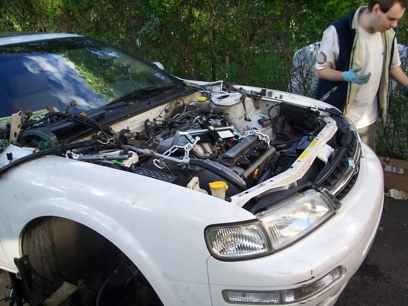
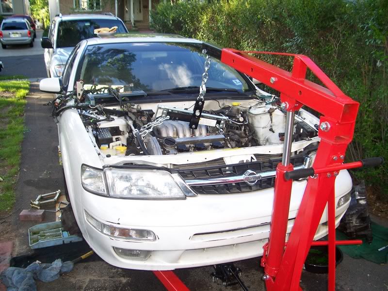
Now here’s the (first) fun part: taking out the VQ30DE!!!!
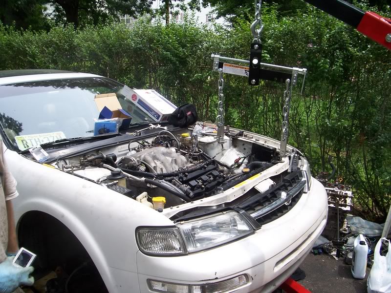
Get your cherry picker engine hoist. Hook up the engine leveler to the engine. Here’s what I did. There are 4 points of contact. Bolt it onto the 2 14mm bolts on the timing chain cover, right above the motor mount, and the remaining two, bolt them onto the 17mm bolts for the transmission bellhousing. This should provide a pretty sturdy base to hold the engine. Make sure no fuel lines are kinked, and make sure there is ample clearance for the chains, and none of them bind.
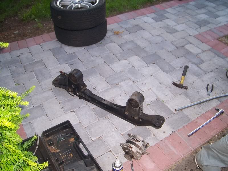
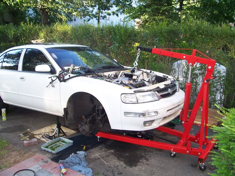
Connect the cherry picker, and apply just enough pressure to hold the engine without it falling. Now, some brave soul (me) must go and disconnect the 17mm bolts that hold the crossmember on. Also, remove the 17mm motor mount bolts. Use a LARGE breaker bar, on in my case, a good impact wrench. There are 2 17mm bolts in front for the crossmember, and 2 in back. Be careful that you’re not underneath, it’s pretty heavy. When you disconnect all motor mounts and the crossmember, move it out of the way. You’re almost there. Well, almost halfway.
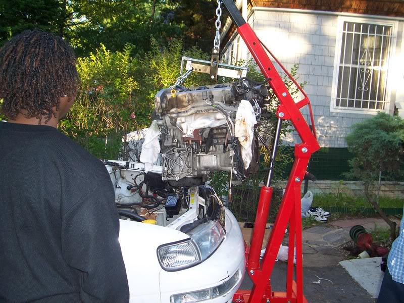
Disconnect the 14mm bolt and nut from the remaining motor mount, and now the engine should be entirely supported by the engine hoist. Carefully lift it up, making sure that it is not binding anywhere. You don’t want the engine falling. Lift it until you can roll the engine hoist out of the way.
Put the engine down, and take a break and get a drink. You just took an engine out of a Maxima.
2. Prep the VQ35DE
Here are the meat and potatoes of the swap: Changing out the timing components.
The first thing to do is remove the engine mount that sits on the timing cover, the crank pulley (20mm), and remove the various 10mm and 12mm bolts that there are. To fully remove the timing cover, you need to remove the lower oil pan, (all 10mm bolts), but be careful that you pry with a very small flathead screwdriver, and make sure not to dent. This can leak VERY easily if it’s dented and it goes back on the car. You can use either the 3.5 or the 3.0 lower oil pan (just the drain plug is different), it doesn’t matter, so if you mess up and kill one oil pan, don’t sweat it, just don’t do it again.
When you remove the oil pan, there are 2 12mm bolts holding the inner timing cover on.
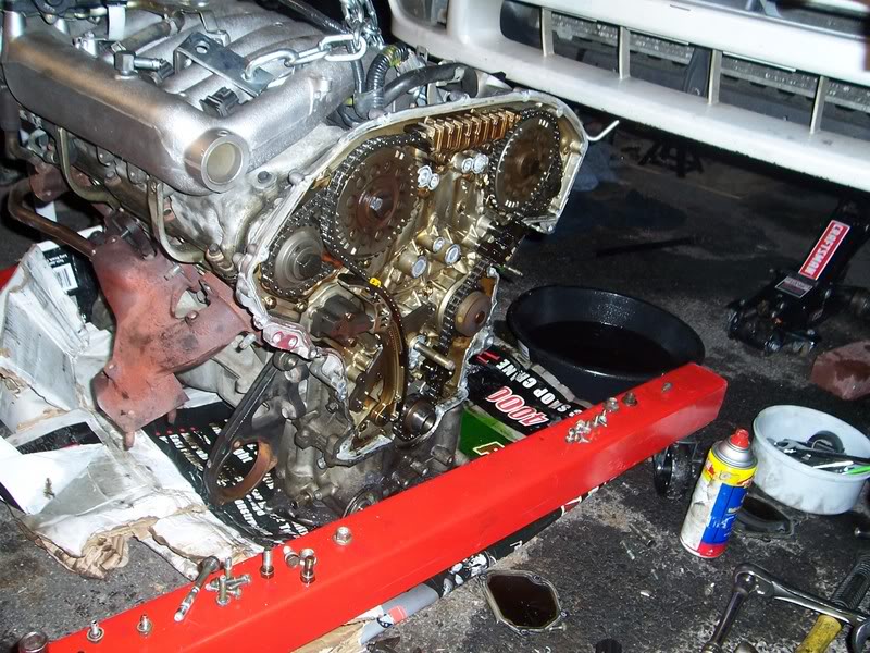
Remove these, and pry the outer timing cover off. I recommend using a pry bar on the side where you can get some leverage, and be very gentle. Although it is aluminum, it can easily crack. The factory sealant that Nissan put is very strong, so give it a good 5 minutes of work to completely remove it. There are 2 dowels at the bottom of the timing chain cover that you need to clear for it to come off. It must come off these dowels at exactly the same time.
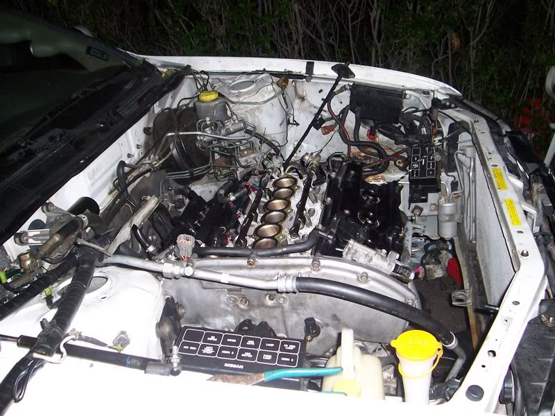
When the timing cover comes off, it should look like this:
Now we’ll take off some timing components.
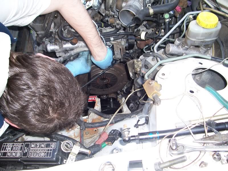
To take off the main timing chain sprockets: open the valve cover (front one will do for now), and hold the intake cam with a 1” open-ended wrench. Use a 22mm open-ended wrench to take off the bolt. This bolt is TOUGH, but do not use air tools on it. I cracked a cam before, they can be pretty fragile. This part it’s a lot easier to do with 2 people (one loosening the bolt, the other holding the cam.)
Once that’s off, you can take off the chain guides (12mm bolts), and the other cam sprocket in the same manner. Then you can take off the chain. Make very sure of where you put these parts. After you remove the timing chain, you can remove the water pump, which is held on my 3 10mm bolts, and be careful, when you pry it out, a lot of coolant will flow out. Also, take off the tensioner (2 10mm).
*Side note: You will want to take off the intake manifold to gain access to the rear valve cover, so go ahead and get that out the way. You can cut any vacuum lines, you won’t be using them again, and it’ll be a lot easier. The hardest part about taking off the intake manifold is the removal of the throttle body. It’s connected to coolant hoses, vacuum hoses, and all these will need to come off in addition to the 4 10mm bolts that are on there already.
Now we take off the secondary cam gears (exhaust cams). This is a 17mm bolt, and it comes off exactly the way the other ones did.
Now that we have the cam sprockets loose, squeeze the tensioners and hold them there with a thumbtack or small nail (there’s a little hole you can squeeze it into and hold it in place). Now you can simply pull out the cam sprockets from the cams, and the secondary chains with them.
Remove the various 10mm bolts that hold the inner timing chain cover on. Also remove the pieces that go in between the timing cover and valve covers, there are 4 10mm bolts on each.
Remember where you put all of these **VERY IMPORTANT**
Now you can pull off the inner timing chain cover. Use a pry bar, using any points of leverage that you can find. I found the inner timing chain cover was a bit easier than the outer.
Now that you have the VQ30DE taken apart, you guessed it. You have to do the exact same to the VQ35DE. First, make sure the engine is at TDC (top dead center). The way to do this is to line the crank pulley (second mark) with the mark on the water pump drain back plate. This is also explained more thoroughly in the FSM.
I’ll save some space, since it’s the exact same procedure, only the intake cams need 19mm bolts, rather than the 22 on the VQ30DE. The procedure for taking apart the engine is almost exactly the same.
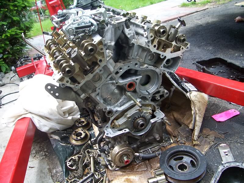
When you’re done with stripping the VQ35DE you’ll end up with something like this:
Here’s where you have to CLEAN, CLEAN, CLEAN!!!
Take out your gasket scraper and cans of brake cleaner. Scrape off every last speck of factory sealant (from the block and both timing chain covers) with the scraper (you’ll go through a few blades), and be sure to get in every nook and cranny. A sharp knife will work in places the gasket scraper can’t get to. When everything’s off, go over it a few times with the compressed brake cleaner (it’s non flammable and dries fast, but the cans get used up quickly.)
Mount the cam journals (thing in between the timing cover and valve cover) from the 3.5 on the engine, then test fit the timing cover. There should be two bolts out of place. This is where you must drill to ensure the bolt goes through. Only a small amount needs to be taken away. Make sure you clean any metal fragments that remain on the inner timing cover. While you’re on this step, you can install the cam tensioners from either the vq30, or the vq35, they both fit.
Make sure you have The O-rings on the engine (the orange ones) before you put on the timing cover. I used Black RTV sealant, and applied a nice, even bead so it doesn’t puddle up and make a mess in places. Oil leaks are the last thing you want when this thing goes together.
Put sealant everywhere designated. If you don’t know where, consult the FSM, but it’s pretty self explanatory. Any small, smooth surface needs sealant. Double check you have everything properly covered with sealant, then *carefully* place it on the engine. Now you secure it with the 10mm bolts. The tightening sequence is pretty important, and you have to torque them down to 10-15ft-lbs. The tightening sequence can be found in the FSM.
After you have the inner timing cover, comes the hardest part: setting the timing.
Get the cam adapters and gently tap them on (the set I got needed some slight grinding with my dremel to make them fit.) They’re a TIGHT fit, so be persistent, but don’t smash them on, the cams could crack, and then you’re S.O.L.
They should look like this:
Now you can start putting on the timing components. Put on the timing sprockets, and the secondary chains. Install the water pump. Line up the notches on the sprockets with the marks on the chain. Tighten the exhaust cam sprocket to 85 ft-lbs. It has to look exactly like this, on both sides:
Next, put the main timing chain sprocket and crank sprocket on, tighten the main bolts to 85 ft-lbs, and install the chain, making sure the marks on the sprockets and crank line up with the marks on the chain. There are two similarly colored chains, and one “oddball”. The oddball belongs right at the mark on the crank sprocket. There’s an indentation where it belongs, and there are arrows on the main sprockets where the other links belong. This is also outlined in the FSM. If not everything lines up, turn the cam VERY carefully and line it up. Put on the chain guides and tensioner. This is what it should look like:
Now that we have our timing set, double and triple check. You might want to move the whole assembly to see that it all moves and doesn’t skip a tooth, it’ pretty easy to mess up in this stage.
Install the outer timing cover, making sure to put a clean bead of sealant on it, and getting rid of any old sealant.
Make sure the two dowels go in at exactly the same time, and install all the bolts. I personally didn’t worry about the order of the bolts, I just made sure they were tightened down to 10-15ft-lbs. Be very careful, they can crack easily.
Now bolt up the engine mount, and crank pulley.
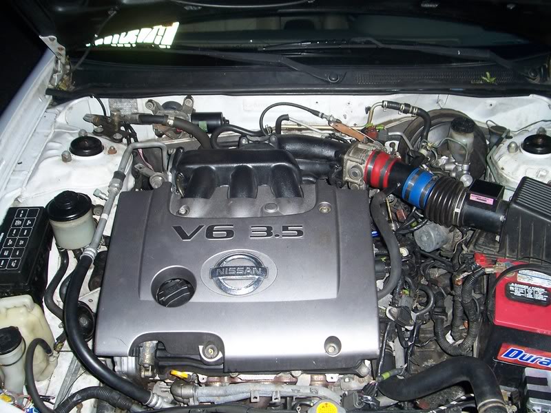
Here’s the finished product,
Now it’s starting to look like an engine. Next we’re going to install everything else that we need from the 3.0, which are the headers (6 14mm nuts), the AC compressor, PS pump, belt tensioner, both belts, alternator, thermostat, and coolant tube on the right side of the engine (the one that houses the Engine Coolant Temperature Sensor). You need this coolant tube because the 3.5 is missing one sensor the 3.0 has, not to mention the various vacuum lines that run on the top of the coolant tube. This tube can be taken off with 4 12mm bolts. The injector sub-harness has to swapped (in the rear of the engine) and the crank REF sensor has to be installed on the bottom of the crank pulley. Connect the oil pressure sender and run the harness so it doesn’t touch the headers, or the power steering pump.
Cut off the 3.0 injector plugs on the harness and make sure you have a lot of wire on the harness. Now cut the 3.5 injector plugs off, and splice them into the harness. If you’re confused about the power and ground, the red one is always the power. You’re only going to do half of the injectors now, as we’ll do the rest when the engine is in the car.
Now you’re ready to install the flywheel and clutch. Make sure the timing ring is on the flywheel (secondary ring behind the flywheel), or else the car won’t start. Take the flywheel off the old VQ30 by first removing the clutch (9-12mm bolts), then removing the 14mm bolts in the middle, and easing out the flywheel. It’s a bit stubborn, but try and pry it on each side and pull gently. Toss the old clutch, it might as well be a Frisbee now.
You can have the flywheel resurfaced, but mine was in good shape, so I just went over it with some 80grit sandpaper and simple green to get the dirt off. Works like a charm. Install the flywheel on the VQ35, making sure not to get grease on the contact area. Then install the clutch, torquing the 12mm bolts to 35ft-lbs.
Now that that’s installed, we can lift the engine from the same mounting points as before, and install the lower oil pan. As with any old sealant, scrape it off, and make sure the surface is clean and smooth before applying the new gasket. Carefully place the oil pan on the engine, and tighten all the bolts.
3. Install VQ35DE
Now the engine’s ready to go into the car.
Again, I’ll save some space and write that it’s the reverse of removal, and through experience, I’ve found it’s a bit easier to put the tranny on the engine outside the car, then lower them into the engine bay, both at once.
You can start putting the harness back on, and now you can wire the other half of the injector harness. The coil packs plug right in, just as they should, just make sure not to overextend the wires for the rear coils, there’s not a lot of room to work with. After you run those wires, you can put on the intake manifold.
Reinstall radiator, hoses, coolant lines, power steering lines, y-pipe, crossmember, axles, and shifter linkages. Fill The radiator, engine, power steering reservoir and tranny with their respective fluids.
ALMOST THERE!!!!!
We have two more things to deal with: The throttle body and fuel.
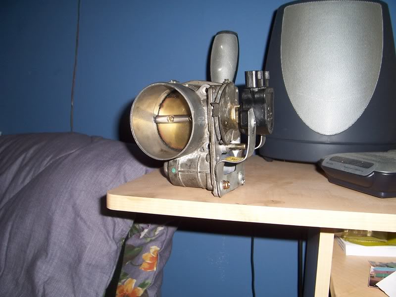
Throttle body: The 3.5 uses a drive-by-wire system that the 4th gen simply doesn’t have, so you’re going to have to make your own bracket to house the throttle position sensor, and throttle cable. First you break the housing of the drive-by-wire system, then you take out EVERYTHING. This should leave you with a rod that you can mount your 3.0 throttle wire bracket to. There’s a little piece of metal that you must use, in conjunction with a lock nut to keep it all in place. I made a bracket out of metal, secured it with bolts, and put the throttle position sensor on that. The hardest part is making the throttle position sensor turn cleanly with the throttle body. You also have to make a bracket to hold the throttle cable in place. Any piece of scrap metal cut to shape will fit. Use your imagination.
This is how mine came out:
Fuel:
The Vq35 uses a returnless fuel system, and the 4th gen has a return system. The solution?
Get a tee and adjustable fuel pressure regulator ($25 shipped on eBay), and run the fuel lines like this:
…..Adjustable FPR set to 52psi —-return line………| Feed—-fuel filter—–tee —– fuel rail
Now make sure you have everything connected, wired up, and sealed.
*FINAL CHECKS*
You can use your stock air box, with a coupler or two. Connect all vacuum lines, including PCV and brake booster to the rear of the intake manifold. Connect the starter, and all grounds.
Connect the battery terminals, and start the car. It should be a little rough starting in the beginning, but it should run pretty well. Let all the carbon and grime burn off, and make sure to give it a tune up after 1000 miles.
Notice I didn’t include a guide on how to hook up the variable intake manifold. I did so for a reason – I didn’t use it. I modified my intake manifold (dubbed V-Spec), so I have more air volume at all rpms. If you want this done, please inquire.
Afterthoughts
Any ECU will work with this swap, I’m running a 1998 auto ECU (stock), but I do have some Check Engine lights. Personally, they don’t bother me, but a bit more work and planning has to go into the swap if you don’t want check engine lights. I have codes for the IACV (not connected), and EVAP system (not connected)
You cannot use a strut bar with the 3.5, the manifold sits too high. I’m currently working a way around that, however.
How long does this swap take?
Mine took about 4 days, doing everything carefully, but it can be done over a long weekend. There was a point where I had both engines taken apart, where it was a bit overwhelming, and I thought “I’m not going to have a car to drive next week”, but you get over it when you’re working at a steady pace.
Is it worth it?
In one word: Definitely.
Thanks:
NYCMAXIMAS.ORG – Can’t thank you enough.
Vipervadim – couldn’t have done it without him & his green tea!!!! He’s very knowledgeable, and I’m glad to have him as a friend.
*~Dark~* -He built by engine hoist while we were taking apart the car, saving precious time. He also offered his help here and there. Thanks!
Tilleys99 – For making the cam adapters
M&RMAX – For giving me an awesome deal on the VQ35’s I bought. – It was my first experience with Rob and it definitely won’t be my last!
CMAX – For giving me advice over the phone about the shifter linkage and clutch
Meccanoble – For giving me a new shifter bushing, and helping me with the same problem
Liquidvenom – For using his strength in lifting my tranny and aligning it with the car. Thanks, Will!
SMX95 – For helping me with any questions I had automotive related
Krismax – father of the 00vi – for letting me drive his vq35 4th gen and getting me hooked!! Should you have any questions, PM me on nycmaximas.org or maxima.org, username tavarish.
When looking for parts, you usually refer to them as driver side or passenger side. However, there are often times where all you see is either an “LH” or “RH“. While it may seem self-explanatory, there are some people who get it confused and end up ordering the wrong parts. So here’s what they mean (for USA based vehicles):
LH = Left Hand (Driver Side)
RH = Right Hand (Passenger Side)
Example: The fender below says RH. This means it’s for the “Right Hand Passenger Side”.
I’m sure there’s a ton of threads here on this, and I’ve seen YouTube videos, pictures here and there, and lots of other tidbits of info scattered about, but I just wanted to add one more to the list. Feel free to ignore this thread if it’s useless, but I’m hoping it will help someone! If I’m giving bad info here, someone let me know!
Overall, this isn’t a hard job, just tedious. I’m doing it with the engine out of the engine as I’m swapping it into a 5.5 Gen, so the upper oil pan is already removed and I’ll be going from there.
Most stuff I’ve seen in my travels says to replace all three chains, the main tensioner, the top guide, the slack guide, and the two small guides in the camshaft chains. Might as well replace the water pump while you’re in here, too!
I went to my local Nissan dealer and asked them for the parts needed to do this job, and this is what they sold me. They assured me that this is what their technicians replace when they do a 6th gen timing chain job:
13028-ZK01C – CHAIN-CAMSHAFT – Small camshaft chain – Qty 2
13028-ZS70A – CHAIN-CAMSHAFT – Large Crankshaft Chain – Qty 1
13070-7Y000 – TENSIONER ASSY-CHAIN – Main tensioner – Qty 1
13085-7Y000 – GUIDE-CHAIN,TENSION SIDE – Top Chain Guide – Qty 1
13097-ZK01C – TENSIONER FACE – Small tensioner shoe – Qty 2
13510-7Y000 – SEAL-OIL,CRANKSHAFT FRONT – Front seal installed in front timing cover – Qty 1
15066-ZL80A – SEAL O RING – Small o-rings in studs near top left and right of timing cover – Qty 2
I’m not sure why they don’t replace the IVT rings, maybe I can purchase those as well, I’ll add them to the list!
Let’s get started!
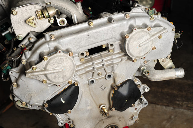
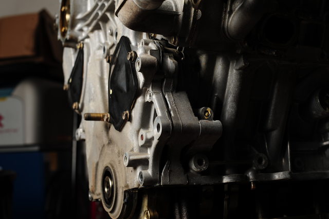
Quick overview of where we’re at here: Front of a 2005 Maxima VQ with 55k miles, this was an AT but that doesn’t matter since the oil pan is already removed. I’m doing this while I’ve got it out of the car so I don’t have to do it again for a long while.
You don’t have to remove the upper oil pan to pull the timing cover, but you DO have to unfasten the two bolts that attach it to the cover. If you don’t, you’ll split your cover when trying to pry it free. This means you must remove the lower oil pan to get to those two bolts. They are the two shown on the right of the image above, the very long one, and the short one.
You’ll also need to have the engine mount bracket removed, in the above picture it’s already taken off.
The problem with the service manual is that it specifies removing everything, including the rear timing cover, so it has you remove a lot of things that are unnecessary, like the valve covers and variable valve timing solenoids. I didn’t remove them to do mine, but you can if you’d like. Just need to get more gaskets and o-rings.
You’ll need to remove the crankshaft bolt if you haven’t already, it’s a bear to pull off since it’s torqued to 36ft-lbs, then rotated another 90°. Plus it’s been there awhile. It took a friend and I to hold the flex plate and run a large breaker bar on it in order to get it loose.
The manual has you remove the IVT covers, which you have to do because they have o-rings and seals inside them. However, you can leave the black water pump and main tensioner covers attached, no reason to remove them since you are removing the entire timing cover.
The IVT covers need to be pried off as they’re RTV’d on as well as held in place with o-rings, so I used a large prybar to gently pull one side away enough to slip a large screwdriver in, then wiggled the cover back and forth while gently pushing the screwdriver in further to help pull the cover off straight. At the same time I was cutting around the outside of the cover to help remove RTV, since you’re mainly wanting to be working against the o-rings, not the RTV.
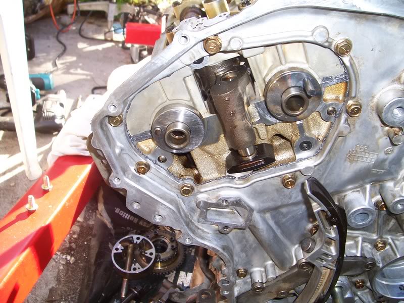
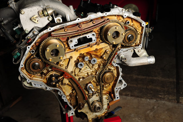
Now that the covers have been removed, the large sprockets are exposed. The main cover can now be removed.
The FSM shows you the proper order in which to remove the bolts so the cover is de-torqued correctly. This may or may not matter, but I followed the guide.
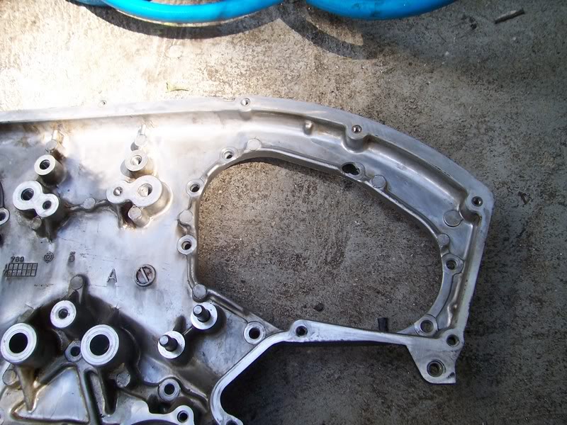
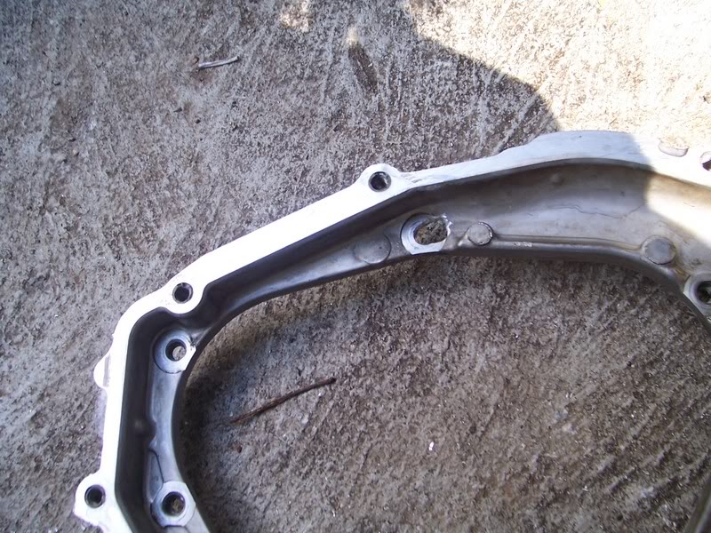
Once all the bolts have been removed, it’s time to pull the case. There are two slots at the top of the case, denoted in the FSM as spots to pry at. These work well for the top, but getting down to the side, it’s more difficult.
I found a third location to pry at, which seems to work well, and is far enough back from the mating surfaces that it shouldn’t cause marring if you use a screwdriver:
The location just above the bolt hole nearest the camera in the photo is a slot that is exposed even when the cases are stuck together, and should help get them pried apart. Remember to pull it off evenly, and use a knife to cut around the outside should you need to, which may help with the initial prying near the top.
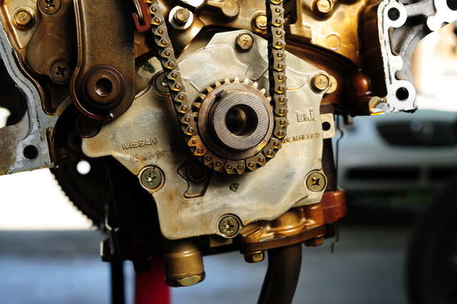
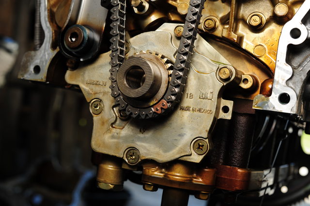
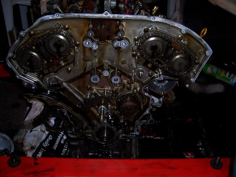
Once that’s off, you’ve got the exposed timing chain area!
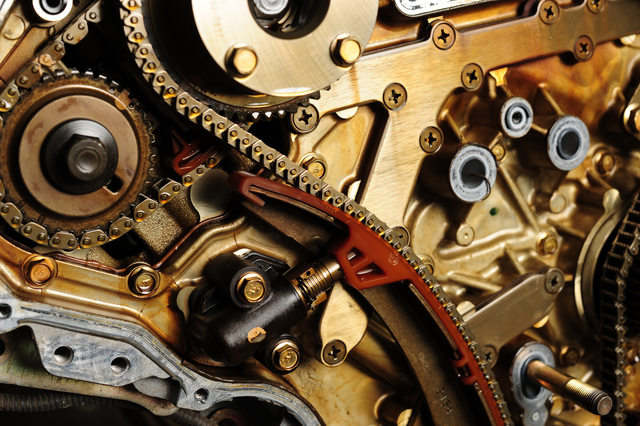
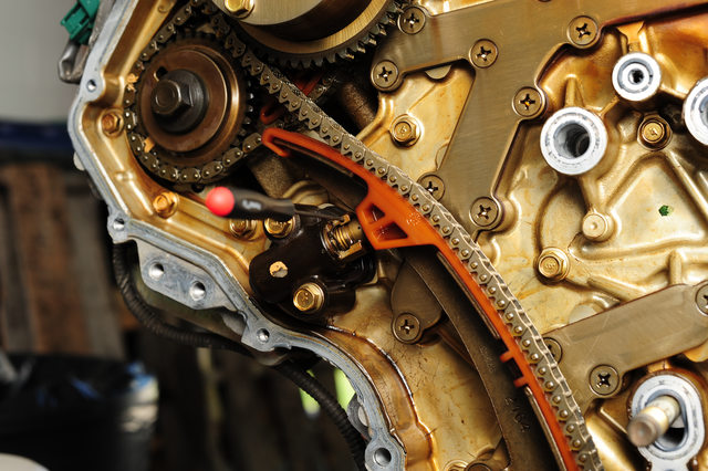
Here’s the main problem, the ‘slack guide’ as Nissan calls it. This part seems to have been engineered with plastic that is too brittle, and too thin near the top, causing it to break off and drop down after some time in the oil.
The part has since been superceded by a newer part, which seems to be made from a different material, as well as having a beefier upper corner.. You can see on the old one where the plastic is already bending away from the metal, this probably would have broken some number of miles down the road.
And here is one of the other tensioner guides you should replace, which may or may not also have worn considerably depending on mileage.
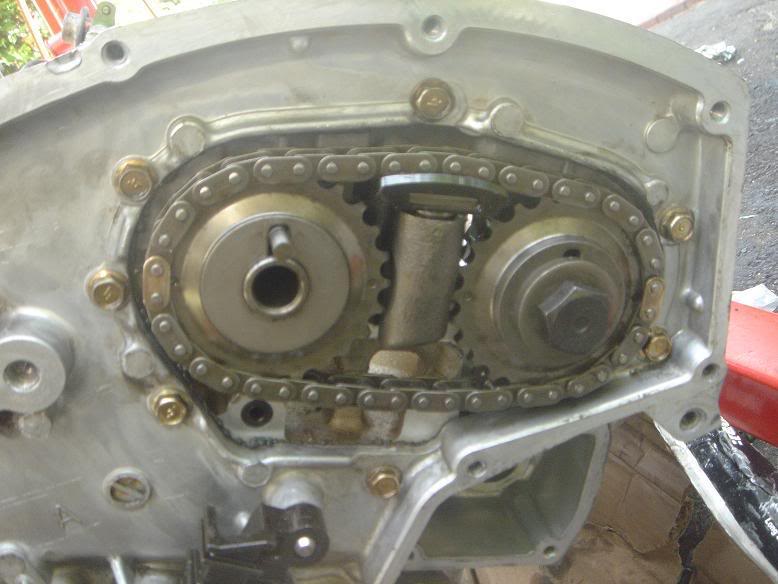
Now that the cover is off and everything is exposed, we can see the chains and the sprockets. Now TDC has to be set on the engine, and an easy way to do that is shown in a few youtube videos as well as here.
Here, I would recommend that you take the time to loosen or break free (NOT REMOVE) the bolts on the four camshafts. These things are torqued to around 76 ft-lbs and have been in there for awhile. It took my 1/2″ impact a few good hits to get them moving, and better to do it now while you’re under tension on an old chain and everything is timed, than to try and do it individually. If you’re removing the valve cover you can ignore and just throw a wrench on the camshaft flats to hold it in place (according to the FSM).
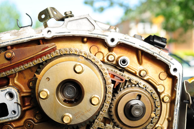
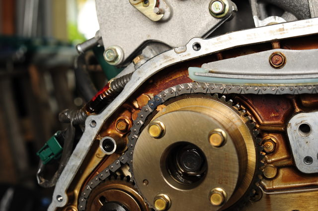
Reinstall the crank drive pulley, or use a large nut as a spacer for the crankshaft, so you don’t bottom out the bolt in the bore when using it to turn the crank. Screw the crank bolt back on and use a breaker bar or large ratchet to turn the 19mm bolt clockwise, until the notches on the large sprockets (intake), and the keyways on the small sprockets (exhaust) are all pointing ‘up’, with respect to the angle of the block on each side.
The small dot punched in the large pulley and the keyway in the small one are both pointing in the same direction. This should be the same for the other side of the engine. The keyway in the crankshaft should be pointing at around 11 o’clock position.
With TDC set, tension can be relieved from the chain. The main tensioner has a small hole in it, and the piston itself has a deep groove near the end of the piston. The piston must be compressed down into the bore enough for the slot to line up with the hole, at which point a ‘suitable tool’ can be inserted. In this case I’m using a small allen wrench, which worked well throughout the repair.
Important!: The small black clip barely visible behind the slot must be squeezed while the tensioner is being compressed. It prevents the tensioner from collapsing back into the bore should the spring or something else fail internally. Squeezing it releases the clamp and allows you to push the tensioner back.
You should be able to compress this by hand since the guide gives you a slight mechanical advantage.
With the tension removed, the tensioner can now be unbolted from the plate and set aside. If you plan to reuse the tensioner, make sure the pin stays in the hole, or the piston may fire out of the bore and leave you with a borked tensioner! If you’re replacing it, the new tensioner should come with a pin already installed in the hole. Leave it in place until you’re completely done with the chain installation.
New (left) old (right):
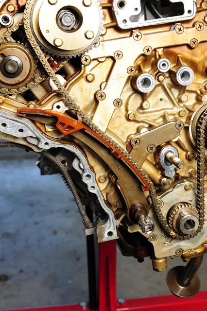
With the tensioner removed, the chain is now slacked and you can remove the top chain guide (above the camshaft sprockets), slack guide and the chain from the sprockets and water pump. The right guide can also be removed and replaced if desired now.
Next, the small tensioners have to be compressed.
I used a small squeeze clamp to do the job, which worked very well, and since you can’t put a ton of torque into them, which prevented me from breaking something like a screw clamp might. I clamped between the chain and the back of the tensioner, then inserted a small tool into the hole. It didn’t go as deep in these as the main tensioner, but still held. I then released the clamp and made sure the tensioner stayed compressed. Make sure not to bump the tool while you’re working!
Next it’s time to remove the camshaft sprockets and chain.
Remove the bolts holding the camshaft sprockets in place, and make sure you note they are different sizes, the longer one goes into the larger sprocket.
The chain should come off along with the two sprockets. Make sure to note their orientation. The right and left banks are using different markings; facing the timing cover, the left bank uses dots, and the right bank uses slots.
Although you may be able to get the chain off without removing the exhaust (small) sprocket, depending on the wear of the tensioner, it will have to come off in order to get the new chain on.
With the sprockets and chain removed from one side at a time (so you don’t get them mixed up!) The guide can now be removed. This is quite difficult, it’s a snap-fit and it really didn’t want to let go. I ended up using a screwdriver to pry the guide off while pushing inwards on my makeshift pin to make sure it didn’t pop out, and finally got it free.
I used the same technique I used to compress the tensioner to install the new guide. It’s pretty tough to get them on, so the clamp helped a lot. I made sure to hold that pin in place while doing it to both keep the plunger from popping out, but also from sliding all the way in instead of clicking into the guide.
Repeat for the other side, and then we can reinstall the camshaft sprockets and chains.
Now that the guides for the camshaft tensioners have been installed, the chains and sprockets can be installed.
(Quick note here though, this is a good time to get in there and scrape off all that RTV from the face of the timing cover, as the chains aren’t here to get in your way, or get all dirty from flecks of RTV falling into them! I took this time to clean the face up nice and neat.)
First, the new chain should have 3 colored links.. Two right next to each other, and one opposite them.
The single link goes to the dot or slot (depending on left or right bank) on the large sprocket, and the two small go onto the small sprocket’s dots or slots.
First, line up the large sprocket, since it’s on the backside and won’t be visible when installing.
Next, line up the two marks on the front of the small sprocket. Once aligned, you can carefully side them back on, which may take a bit of work with the new, non-worn tensioner and new, slightly-tighter chain.
The old chains’ colored links may be hard to see, and may or may not be lined up correctly, due to what position the engine was in. As long as you line up the new chain’s links though, that’s what counts. Install the same as the other side, ensuring the sprockets are seated completely and the chain is in the center of the tensioner guide.
On my engine, I opted to replace the water pump as well, as preventative maintenance even though there was only 55k on it.
A helpful hint here.. The block still contains coolant in it, even if you’ve drained the radiator and removed the oil cooler. There’s a little drain bolt that lives beside the water pump to help drain the remainder of the coolant from the engine, unscrew it before you do the water pump and you’ll prevent a mess!
It’s the small bolt in the center of that triangle in the middle of the photo.
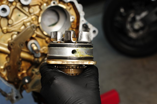
I removed the three 10mm bolts holding the water pump in place. I then pried it out using a large prybar on the forward set of sprocket teeth, so my bar would not pry against the water pump housing itself.
It appears on my pump that the seal was leaking slightly. The area between the two rings is an area connected to a ‘weep hole’, which allows oil or water that begin to leak past to exit the engine through an opening in the block, rather than contaminate each other. In this instance, it appears coolant has been leaking through one ring, so this was a good thing to replace. The center hole is for coolant or oil leaking through the shaft seal to be able to drain down to the weep hole as well.
With the water pump installed, it’s now time to install the large timing chain.
The chain has three colored links, two blue-ish and one copper. The copper link goes to the slot opposite the keyway on the crank sprocket…
And the blue-ish links each are positioned to the dot on each of the large sprockets.
Once the chain is installed and settled properly along all the sprockets, including the water pump, the upper guide can be installed, followed by the slack guide and tensioner.
I found it easiest to install the lower bolt of the tensioner, and swivel it up against the slack guide, as there is still a bit of tension after the upper guide is installed. Pushing firmly on the chain will rotate one of the camshafts to give you a bit more room. Install the bolts and torque to spec.
Once the guides are all installed and torqued, and the tensioner ready, the chain correctly set to the timing marks, and everything looks good.. you can then release the tensioner. Pull on the slack guide a bit while pulling the pin, and the tension piston should take up the slack in the system.
It’s a good idea to snug up the camshaft gears at this point, reinstall the crankshaft pulley or your spacer, and use the crankshaft bolt to spin the engine slowly. You shouldn’t encounter any stiff resistance. If you didn’t pull the plugs, there will be some air resistance, but that will lessen as you hold the crankshaft in that position, and you can continue to turn it. If at some point you can’t turn it at all, and it feels locked in position, that’s bad, and could be valves hitting pistons.. recheck all the timing marks.
This is when I torqued down the camshaft bolts (Don’t forget!). They’re quite difficult to torque when the engine is out of the car; I had to use a prybar in the flex plate gear to hold the crankshaft steady while torquing them.
Once they’re torqued up, you should be good to go. Make sure you torqued all the bolts holding the water pump and chain guides to the specs in the FSM.
Done!
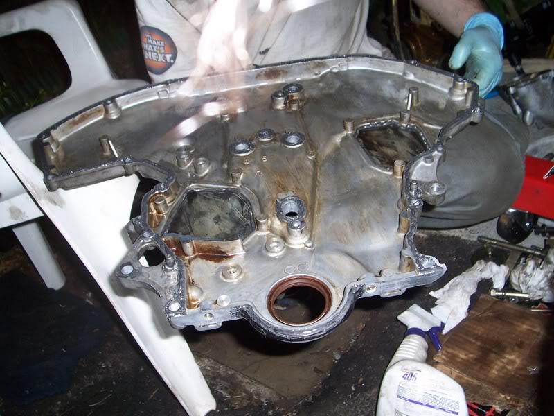
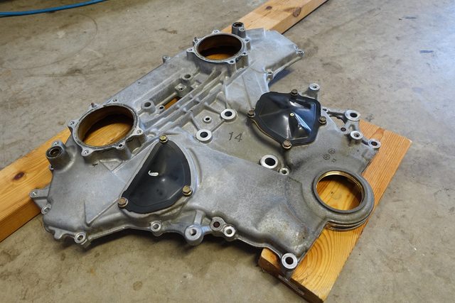
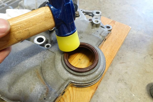
I took the opportunity to set up the cover on a couple of blocks, pry out the old front seal and replace it with a new one.
I used a soft mallet to very slowly and gently tap in the new seal, along with a bit of oil to make sure it slid in nicely. A block of wood would also work, if you don’t have a soft hammer.
I wiped all the mating surfaces down with isopropyl alcohol, and used my compressor to blow all of them off to make sure I wasn’t leaving any pieces of RTV left on the covers.
Unfortunately, I don’t have any photos of putting RTV on the main cover, but it’s fairly straight forward. I used Permatex Ultra Black RTV sealant, and deviated from the FSM slightly in the technique.
While the FSM calls for applying the silicone, installing and tightening the cover, the RTV bottle says to apply the bead, install the cover with bolts finger tightened just until it starts to ooze out from the mating surfaces, then let it set up for one hour. After that, complete the torquing process. I can understand why this is, as the RTV will cure a bit before being deformed into the final shape.. It will also provide the pressure against it necessary to prevent any leaks. I used the method printed on the RTV.
Now, you may need to also clean up and install the front oil pan seal at this point as well, if you did not remove the oil pan. Since my upper oil pan is already removed pending a swap, I didn’t have to worry about this, but if you did not remove it and only unbolted, then you’ll need to reinstall the oil pan seal, and most likely RTV in the spots specified by the FSM, and/or where you saw the RTV originally placed from the factory.
For the initial tightening, this is what I saw at the cracks:
I let it set up for one hour, then torqued all the bolts down to the specified torque, in the specified order:
After taking care of that, I began to RTV the other covers, installing them one by one, cleaning them in the same way as the main cover.
Fully RTV’d main cover
Installing the cover, making sure the dowel pins line up and it’s being pushed in straight. I also oiled the plastic seals on the lid that slide into the intake camshafts.
You can see a slight squish as the RTV is compressed.
After gently snugging up the bolts with just fingers on a socket
After waiting another hour, I torqued down the bolts to their spec, in the order the FSM specifies.


")


 ** The injector rail may also be removed, but that isn’t necessary.


 Remove the O2 sensors (I use a 7/8” open ended wrench) and remove the y-pipe. There are 8 bolts, 14mm if you have an aftermarket y pipe (as you should), and 10 bolts, 8 14mm, and 2 12mm bolts holding in the y pipe.
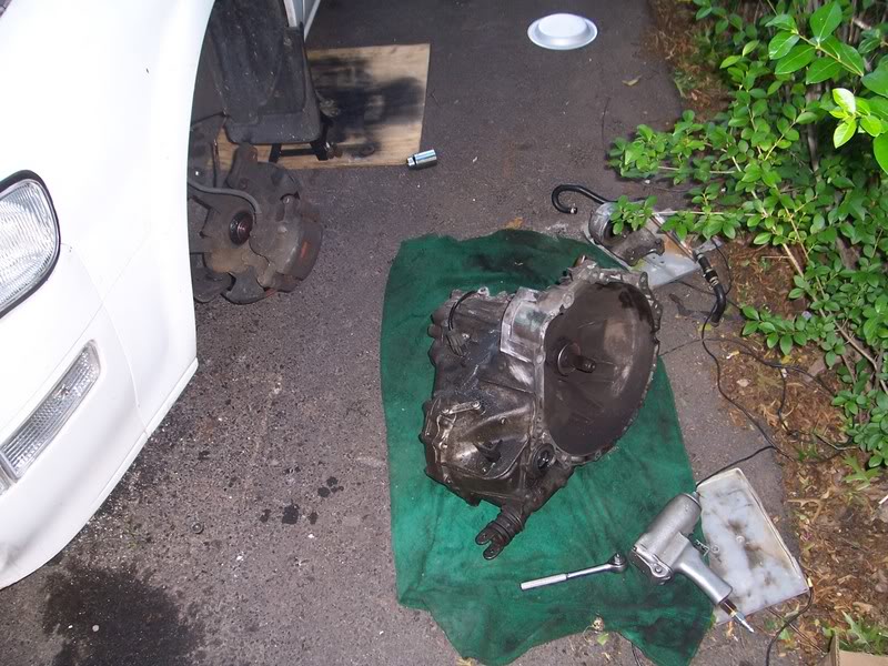

 Make sure you have The O-rings on the engine (the orange ones) before you put on the timing cover. I used Black RTV sealant, and applied a nice, even bead so it doesn’t puddle up and make a mess in places. Oil leaks are the last thing you want when this thing goes together.