Credit: Thomas Perdue Jr


![]()


")
")
Introducing Racingline’s new High Flow Pre-Cat exhaust systems for the 2004-2008 Nissan Maxima. Engineered to be a 100% bolt on, these units feature fully metallic core Stainless steel high flow cats that flow more than double that of the OEM units they replace, resulting in 8 HP and 14tq at the wheels.
Price: $499.99
Part Number: HFPC-A34
Designed as a “header alternative” for cars that are experiencing failed pre-cat units. Until now, if a pre-cat failed your only options was customizing a header set (that takes upwards of 8-10 hours installation with no guarantee against SES/CEL lights) or going to the Nissan dealer and spending $700 each on the pre-cat units.
Racingline HFPC’s feature:


PDF Version: HFPC_Install


![]()
")
Price: $230.00-$250.00
Brand: TurboWorks
Notes:


![]()

This is another option for buying O2 Simulator. They have been testing and fully working on 2002-2003 5thgen Maximas. Should also work on 2004-2008 6thgen Maximas as well.

Price: $199.98
Website: http://www.area74.ca/product/io2-universal-oxygen-sensor-simulator/
The iO2 was originally developed as tool to aid in the diagnosis of catalytic converter and oxygen sensor fault codes.We believe this is the most intelligent oxygen sensor simulator available, that’s why we named it the iO2. The iO2 uses the vehicles live oxygen sensor signal to emulate and output a signal that closely resembles that of a good functioning catalyst.
The desire to simulate an o2 sensor begins with the desire to remove the catalytic converters to allow free’er exhaust flow. The trouble is, the rear o2 monitors the exhaust content and the PCM can determine if the catalyst if performing or not. If the catalyst is removed, the PCM usually starts reporting P0420,p0430 faults for catalyst efficiency.
Simulation approaches in our research showed two basic idea’s, an electronic and a exhaust spacer approach (defoulers)
Let’s start with electronic, the 555 timer. Developed years ago the 555 timer was and still is the electronics hobbyist dream.The 555 timer was setup in such a fashion to simply output 450 mv to keep the PCM thinking the rear o2 was present.
However as PCM’s grew in software function, tests were added to check if the rear o2 was actually able to produce a voltage range of 0-1 volt.Of course, this made the original 555 design obsolete, so the output of the 555 was changed to pulse from 0-1 volt at a fixed or even adjustable rate, this is the most current use of the 555 that we know of.
This does work for older technology, however it is hit or miss or will not work for newer PCM’s. It is a unreliable approach that will more than likely lead to an catalyst efficiency fault at some point.
An very common electronic filter circuit, but does it work?
About as well as the 555, yes and no, its once again hit or miss dependent on the vehicle. It will pass the PCM’s test for o2 sensor activity, just like the 555 timer will, but when it comes time to test for catalyst efficiency (p0420,p0430) that’s when they fall short.
The direct approach, this seems to be very popular maybe because electronic approaches haven’t been very reliable, and its cheap. Do they work? once again yes, and no. First they are far from from stealthy, secondly they require routine maintenance.
They are not a guarantee for every vehicle, difficult to get just right and require cleaning from time to time
At any rate, we just wanted to provide some insight based on our research.
The io2 itself, is actually a programmed device that reads an actual o2 sensor voltage, then cleans it up.
The software within the io2 will force the output to act as though a catalytic converter is present in the exhaust. So the PCM will see the signal, pass the o2 function test and when it comes time for the dreaded p0420,p0430 the software takes care of that too.
 The io2 during testing. The io2 was installed on a 2007 Chrysler product to field test the software. This test vehicle was driven in excess of 850 km’s in all driving conditions, with no P0420 or catalyst efficiency codes generated.
the io2 was installed on bank1, input was taken from the bank1 primary O2, the rear o2 sense wire was cut and spliced to the io2 output.
Answer; Many devices currently on the market are based on a 555 timer, or a simple low pass filter circuit. Yes they do work, sometimes, sometimes they don’t, they are hit or miss. The iO2 is a programmed microcontroller with software that creates the simulated output voltage, we feel the most reliable approach.
Answer; you will need as many io2’s as you have rear oxygen sensors (please see our support page). You cannot reliably use a single simulator for two rear o2 sensors, eventually the engine computer on many vehicles will try to test the function of the rear o2 sensors, it may not test each one at the same time, unlike other simulators,the io2’s software is designed to recognize these tests,so simply put, this will not and cannot work.
Answer, YES! as long as you are using a low band O2 sensor as the input (every vehicle uses a low band for the rear O2 sensor) and the output is simulating a low band O2. This includes all vehicles, even Chrysler,Jeep and Dodge products.
![]()
")
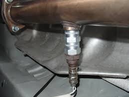
This is the OEM Exhaust Manifold Stud and nut found in the cylinder head of all VQ35DE engines.


![]()

Credit: 02whitemaximase
The OBX headers (02-03 Maxima, equal length y-pipe) have been out of stock for at least a year. For engine performance mods I have the Megan OE-RS Catback installed along with berk/Apexi intake and 5 piece spacers. I have compiled all of the information needed to get these headers installed correctly.
My first photo is of new OEM exhaust gaskets. Look at the part numbers and order those if you plan on doing a header install on a 3.5. Although you could get away with reusing the original gaskets, I would recommend spending 35 bucks for peace of mind.
The front (closest to the radiator) header measurements are as follows:
Runner length from where it meets the flange to where all three join cylinder 2= ~10″, 4= ~9″ 6= ~12″
Prices and part numbers:
The purpose of this thread is to display the newest batch of OBX headers. Exhibit how the install goes and post up some before and after pictures and videos.


My install went nearly flawlessly minus one heat shield bolt being seized and a secondary o2 sensor not coming out of the old converter. I know these headers are made overseas where quality control is not great. With that being said I think no two sets of headers are exactly the same which means that you may need to trim something during your install. I came to a couple of millimeters from having to trim my front motor mount bracket and my rear bracket went on no problem although it was very close. Probably about 2-3 mm from touching and my front bracket is literally 1mm from touching the header. My flex pipe has about 1/4′ space from touching the subframe.
As you can see one of the primaries comes very very close to the front motor mount bracket but it did not require trimming. Although some may be uncomfortable with how close they are, it is no problem. The mount and header will NOT move even though mine are basically touching it does not matter.

The y-pipe comes about 1/4 of an inch from touching the sub-frame cross member. Again this is not a problem. I have driven it like this enough to not experience any noise and the way I see it the motor really only moves front to back so this tight space does not come into play.

In order for the front primary to have enough wire slack to reach the new header bung, you will have to cut the tape holding the group of wires that travels directly over the middle coil from the larger harness that runs along the top of the valve cover. The tape was holding both harnesses together to about right in the middle of the top middle of the valve cover. Easy fix takes one second.

As you can see below the far left plug has to be unclipped from the coolant pipe in order for that primary to reach.

The rear primary wire has to be extended too. From all of my research people here have been saying to cut the primary either at the wire harness and add some wire to lengthen it or to cut the actual o2 wire and extend those by adding wire. Problem is that it can mess with the voltages. The wire is stainless steel which is nearly impossible for an amateur to solder correctly. My method requires NO WIRE CUTTING!!! You need to remove the wire harness cover pictures below and simply separate the o2 wires from the rest of the wires. First, you need to separate it from the green plug wires, then you need to slit the right side of the main harness that fees into the back of the plastic box. PLEASE TAKE YOUR TIME!!! Be very careful to cut precisely and slowly. Doing this will give you enough slack to reach the rear primary o2 sensor.

This next picture shows exactly where my o2 wire is coming out of the main harness. It is wrapped in a black plastic protector. This picture is taken along the firewall from the driver side, so the top of the picture is the passenger side, the bottom is the driver’s side and as you can see the top left is the upper part of that black wire harness box. The fattest harness coming from the box is what you need to slit the side of and separate the 02 wire from. My o2 wire is running out of that harness down toward the middle of the picture.

The following picture is of one of my secondary sensors. I have the antifouler setup and as of about 75 miles no CEL. This secondary is the one with a green plug and red wire cover. The wire running above it is actually the other secondary which is the blue plug with a white wire cover. Secondaries have different length wires so I recommend this configuration.

As you can now see the y pipe outlet is not quite at 2.5″ but pretty damn close

My new wideband bung on the y-pipe.

The relocated rear header primary bung and plugged original location


![]()
")
Price: $330.00 + Shipping (Add $10.00 for new set of Gaskets)
Ordering Info: To order, you can email Adam at SilverSpyder117@Gmail.com
Notes: This will not void any warranty under the Magnuson Moss act. Yes, it deletes the 3rd unmetered cat. No it does not cause any check engine lights or codes. Direct bolt on about 45 min. Install. Yes this will fit 7th and 8th gens alike. This will not fit an Altima SE-R due to the rear header connection only.


About Product & Seller:
Jemini Power Performance was officially founded on 12/28/17 and named after my beautiful wife who God has blessed me with and who puts up with me dedicating my time to this community. This business and group were created for the 7th and 8th generation, Nissan Maxima. We are specializing in bringing back the well sought after performance y-pipe for the VQ35.
We took the Racingline y-pipe and revamped it to a whole new level. Racingline used bare materials such as mild steel, mild coated with aluminum, and 201 stainless steel to produce the initial y-pipe. We had it tested to see these results. Many people have seen the results of this down the road with rust and premature failure.
What we are now bringing to the Maxima community is far better. Top-quality 304 stainless steel construction throughout that will not rust, all custom made gaskets for 2 entry and 1 exit path, shortened .5 inches to meet OEM specifications and a 2 year warranty.
Everyone knows what these y-pipes do and are capable of. If you have questions please ask. From my own experience, I felt a difference immediately after install. Much smoother powerband from the CVT, no lag at all, and steady pickup. From 0 much more responsive and carries that power to well over 100+.
![]()

Credit: pimpin02max
Alright…there seems to have been many many questions about the install of the newer OBX Headers/Y-pipe. So I have decided to do a small writeup on the installation of these headers/y-pipe. So below I have made a faq with some of my answers that should be right but if I am wrong on anything feel free to let me know…and like everything else, this is a guide to help you on your install and any questions you have, so if you screw something up it is not my fault
FAQ
1. Are these worth saving the extra money over the Cattman’s?
(Answer) If you are a do-it-yourself kind of person then yes definitely, the Cattman’s are an awesome product and have no fitment issues whatsoever (I have owned a set of Gen III’s) and the peace of mind is nice, but if you aren’t afraid to do some small modifying and saving around $500 sounds good then yes the OBX headers are for you.
2. Do these make decent power compared to the Cattman’s?
(Answer) The OBX Headers make just as much power as the Cattman’s. Depending on who you ask some will tell you they make more but I think that since the dyno’s differ I would say all around they make around the same power.
3. I have heard you have to extend the O2 sensors, is this all 4 or just the primaries?
(Answer) Alright, when I installed my headers all I had to extend was the primaries which are the O2 sensors in the collectors of the headers…now if you choose to plug up the secondary O2’s then you might have to extend them, I don’t know because I did not hook mine up.
4. Do you have to relocate the rear bung for the primary O2 sensor?
(Answer) Don’t know if you absolutely have to but I would 100%…it makes the install a lot easier and you won’t be so worried about it hitting the steering rack and whatnot. All you need to do is move the bung 90* to the right on the collector and your good to go, you could have a shop do this for you or for the DIY’r you could do it in your garage (like me…lol)
5. Will I throw a SES with these headers?
(Answer) Yes most likely, since you do not have any precats for the secondaries to monitor you will throw a code which is why it is useless to plug up the secondaries to begin with since they will still throw a code because there are no precats. The SES light thrown will not effect your performance at all because the primaries are the only O2’s that affect your A/F ratio. Now all you need is a dual output O2 simulator which you can get from here: http://www.02sim.com/ Some have reported not throwing a SES and most get one. When I installed my Cattman’s I threw one upon first startup, with the OBX’s I have been driving around for 1 1/2 months now without a simulator and have yet to throw a code, but that’s just mine.
6. Should I use the gaskets included with the headers or the OEM ones?
(Answer) Definitely use OEM multi-layer gaskets because the ones included like every other header kit are crap. Now if for whatever reason you have to use them then they are ok but plan on changing them down the road because they won’t last as long as your OEM ones.
7. Is there that much modifications to make these work?
(Answer) That depends on who your talking to. I didn’t think it was that bad. The only modifications I had to do was to move the rear bung 90* to the right, plug the 2 secondary holes in the y-pipe, trim down the crossmember like 1/2 inch for the flex section, and then grind down the rear motor mount bracket peice for the primary tube on the rear header. That’s it. Not bad at all. Some people claimed to have installed them without any modifications but I would plan on doing the above on your install.
8. Do you have to have a lift to install these headers?
(Answer) NO!!!! You can install these with your car on jackstands…I installed both my Cattman and OBX’s with the car in my garage on jackstands. Even with the one peice rear header/y-pipe deal it’s not that bad. The y-pipe header peice doesn’t weigh that much and once you get everything trimmed and out of the way it isn’t that hard to put up on the head.
That’s all the questions I could think of for now, I am working on the Install Writeup as you are reading this so I will post in a little bit, but I hope this helps out a lot with some of the questions and concerns people are having with these headers.
Now bare with me hear as I installed these quite a while ago, so if I left something out please feel free to let me know because this is going off of memory, I didn’t take a gazillion pics either so it will mostly be an overview because I’m assuming you guys can figure out the small details  . So use this as a basis to go off of when you are installing your headers, it’s not an instruction manual but I’m sure it’s a good outline to follow.
Alright first things first. Here is a pic of the bung relocation courtesy of C-Young:

1. Remove your filter, midpipe etc. off of your intake.
2. Proceed to remove your intake manifold (12mm) upper only though.
3. Remove your Radiator fans, only 2 bolts on top (10mm) and 2 on bottom (10mm) unplug them as well.
4. Jack up the car and put on jackstands.

5. Take off the passenger side splash guards.
6.Take off the front heat shield off the header.
7. Undo the 2 front O2 sensors and the rear secondary. 22mm wrench or an adjustable wrench.
8. Unbolt y-pipe completely from the precats and the cat.
9. Unbolt exhaust manifold from head.
10. Drop the front manifold throught the bottom.
NOW THE EASY PARTS OVER….LOL
11. Undo the rear O2 sensor off the rear manifold
12. Now it would be easiest to unbolt the precat from the rear manifold but mine decided to be tricky and stripped out so I couldn’t undo it so it was a little hard to get to the nuts for the header.
13. Unbolt the rear manifold using a combination of underneath the car and from on top to get to the different nuts.
14. Bolt the front header to the head.
15. Go ahead and test fit the y-pipe/header and see where you’ll need to cut (even though you already should know by now…lol)
16. Grind down the crossmember so that it’s not touching the flex section.

17. Now grind down the rear motor mount peice on top that’s almost just like a cover for the top of the mount, this can be kind of tricky, I’ve found it to almost be easier to undo the mount from the engine and cradle and take out of the car and since all you are grinding is a plate you can just cut it all the way off…photo courtesy of datdude20.
18. Your header/y-pipe should now slide up into place.
19. Bolt on header to head
20. Bolt y-pipe to cat and to front header.

21. Plug in your O2 sensors. You may need to use some zipties on the front because my wire was being hit by the fan so I ziptied it so it wouldn’t hit.
22. Double check and make sure everthing is bolted up tight so you won’t have any leaks.
23. Lower car back onto ground.
24. Re-install fans, intake manfold, intake.
25. Enjoy your headers!!!!
![]()


