Tag

Headlights & LED Lighting Mods

Browsing

Community Member Credit: maximase86

Write-Up: cefirowriteup

Tools:

  • Ratchet
  • 10mm deep socket
  • Extension
  • 10mm gear wrench (or normal wrench)
  • Dremel
  • Heavy-Duty Cutting Discs
  • Grinding Bit
  • Scissors
  • Pliers/Channel Locks
  • A friend
  • Wire Crimps/Splicers
  • Panel Poppers (optional)

Needed Materials

  • Galvanized Plumbers Tape
  • Automotive Weather Stripping
  • Double-sided foam tape
  • Zip Ties
  • Wiretaps
  • Electrical Wire

1. Disconnect the ground to the battery terminal.

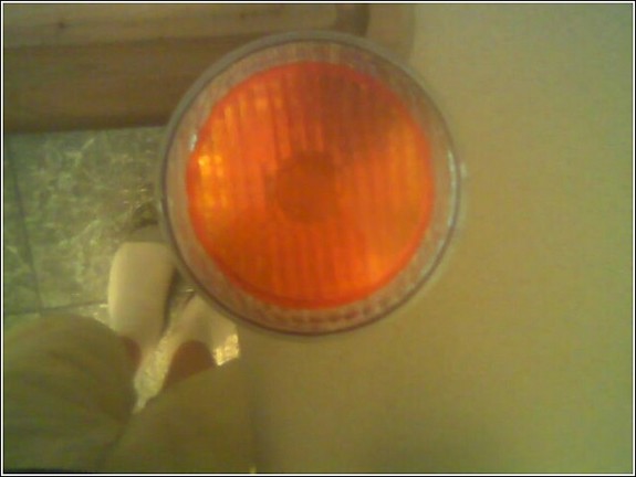
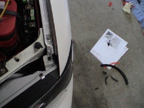
2. Remove the cornering lamps. There is a Phillips head screw that holds the lamp to the headlight. Once you removed the screw, just pull the corner lamp out in the direction the car is facing. Note that the cornering lamp may be tough to remove. Note, keep all your existing bolts and screws as you will need to reuse most of them.

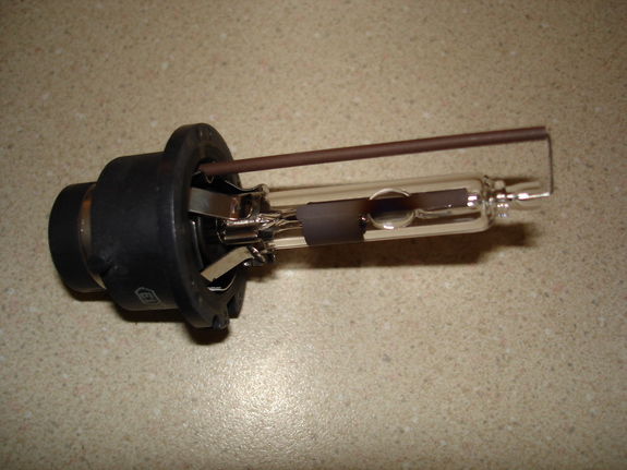
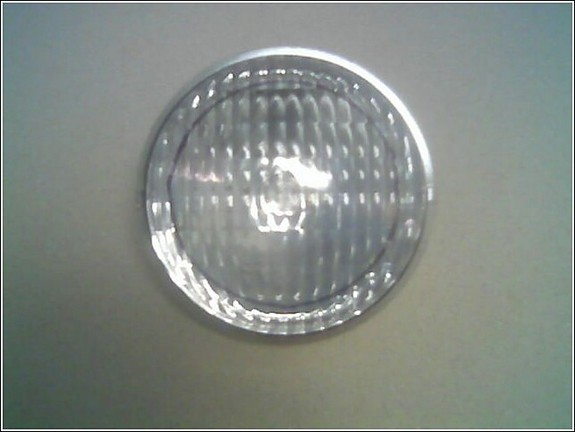
3. Remove the bulb from the cornering lamp as well as unhook the harness. Set aside.

4. Remove the grill. There should be clips near the top corners of the grill. Pop these clips and then lift the grill up and out. Set aside.

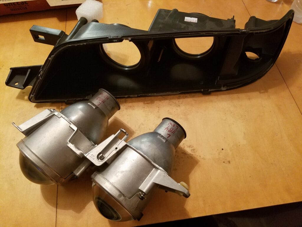
5. Unplug the headlight harness and remove the headlight bulb.

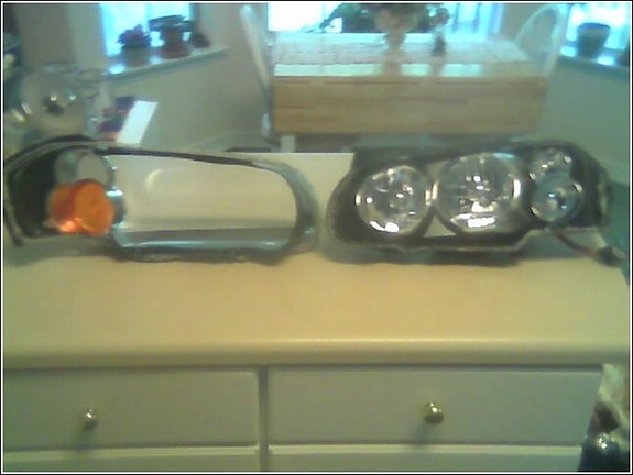
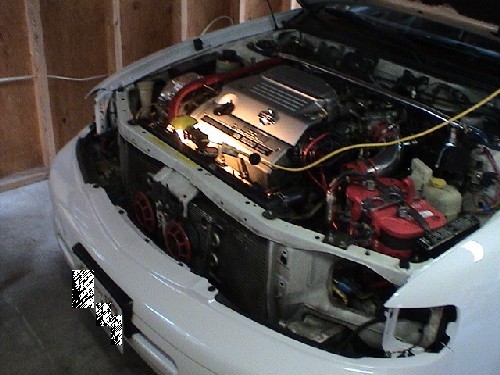
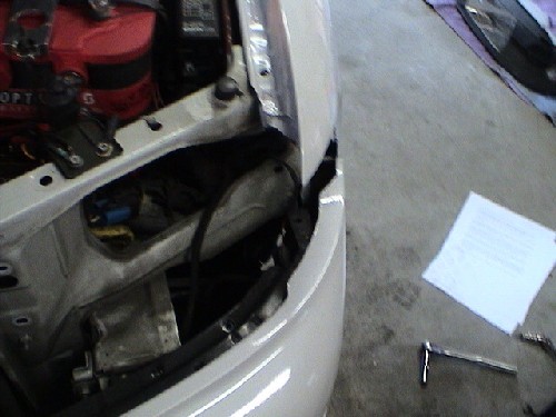
6. Now it’s time to remove the headlights. First, remove the 10mm bolts that hold the headlight to the bracket on the fender. Next, there are 2 10mm nuts holding the inside of the headlights to the car on each side of the radiator. You’ll probably need a deep well 10mm socket, or if you have a set of gear wrenches, this will help out a lot. Once that is removed, pull the headlight in the direction the car is facing. Watch for the adjustment bolts, as they like to snag on things when pulling out. Your car should look like below when you’re finished.

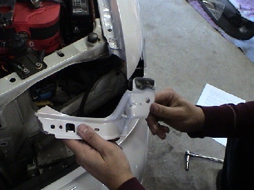
7. Next you will need to remove the little black trim piece that sits under the original headlight. There should be about 3 10mm bolts that hold them in place. Remove them from both sides.

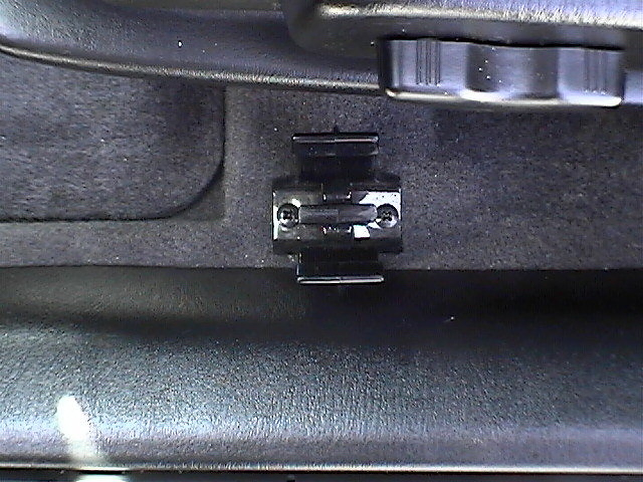
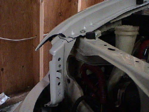
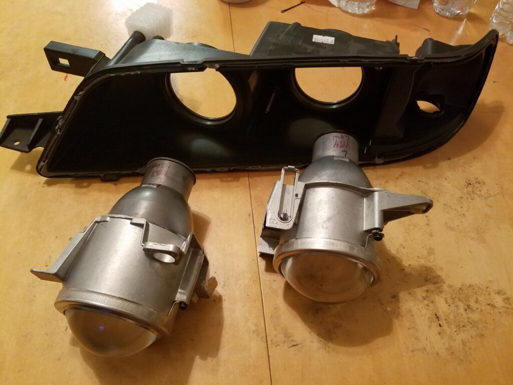
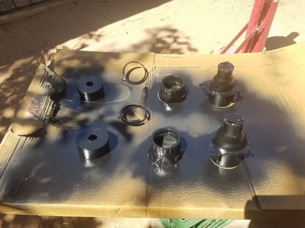
8. Next comes the fun part, time to hack your car up! There are 4 places you want to mark with a sharpie. The main headlight support bracket, the 2 tabs for the corning lamp, and a portion of the frame which you need to make a cut out to allow the lamps to fit. See the following pics:

The upper portion of the support bracket with cut marked.

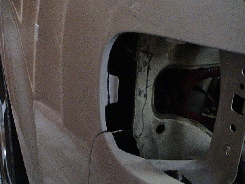
Cornering Light Tab and Frame with cut marked.

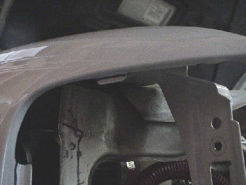
Upper Cornering Tab with cut marked.

Bottom of the headlight support bracket

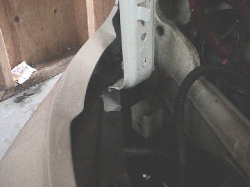
You have 2 options with this. To help give the ability to revert to stock you can do one of 2 things. You can use panel poppers, or some kind of screwdriver to pop the spot welds at the bottom, or you can bend the bracket down.

9. After you made your marks, go ahead and make the necessary cuts. There are few different tools you could use (i.e. grinder, Dremel, etc). The Dremel might provide the best results. You will need to use the heavy-duty cutting discs, and be ready to use 10-15 discs.

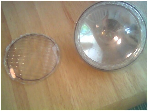
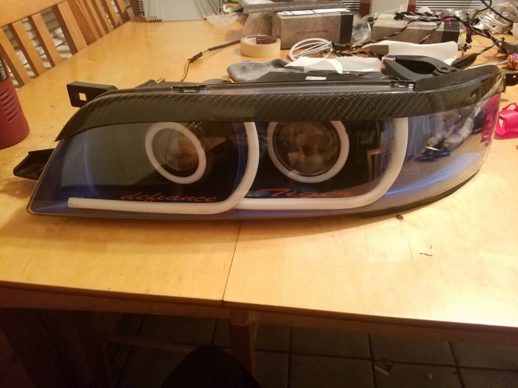
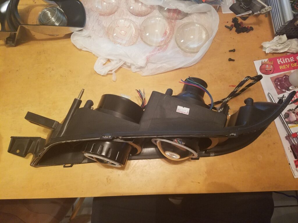
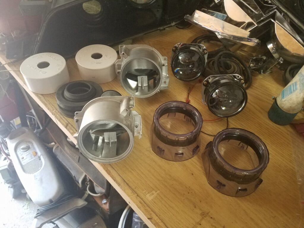
10. Once your finish cutting, and you got the bracket out of the way, it’s time to do a test fitting. Put the Cefiro headlight in place. Make note of any places that might be in the way. Take out the headlight and make cuts as necessary.

11. You may need to make the holes there in the headlight bolts near the radiator larger in order to reduce the gap between the headlight and the fender. It is impossible to get it perfect, but it does help a little.. If this is the case, you can use a Dremel with a grinding bit to enlarge the holes as necessary.

12. Once you have your headlight set the way you want it, you will now need to fill in the gap. (And since you have these instructions because you have a 4th gen, there WILL be gaps).

13. To fill in the gap, you’ll need to get some black weather-stripping. You can usually find a bulk back at your local parts store. What you want to do is with the headlight in place; measure out a piece that will fit the gap best. You may need to do some trimming to get everything to look good. Once you have the piece you need, remove the adhesive backing and attach the weather-stripping to the headlight. Keep in mind; this is sort of a trial and error thing, so you will have to work with it a little before you get everything to work.

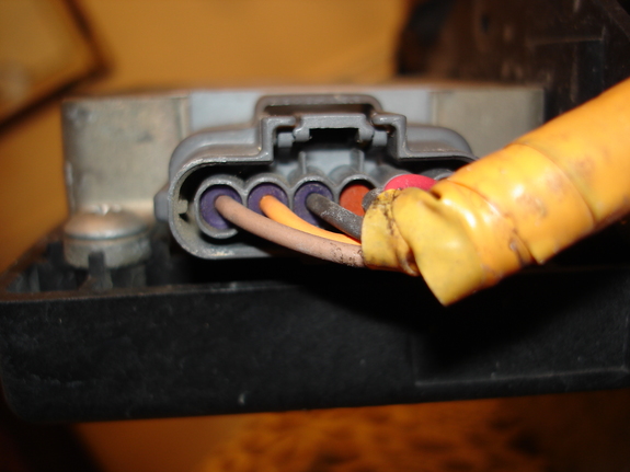
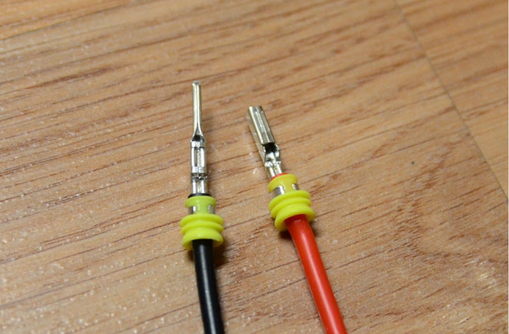
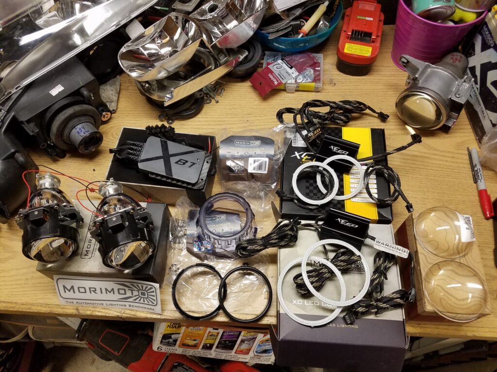
14. Next you want to splice the H4 harness into your existing harness. To do this, it’s easiest to reconnect the ground, and while using a voltmeter, test which wires run which with the lights on. (Black will be ground).

15. Next splice the city lights into the side markers. You may need some extra wire handy to do this

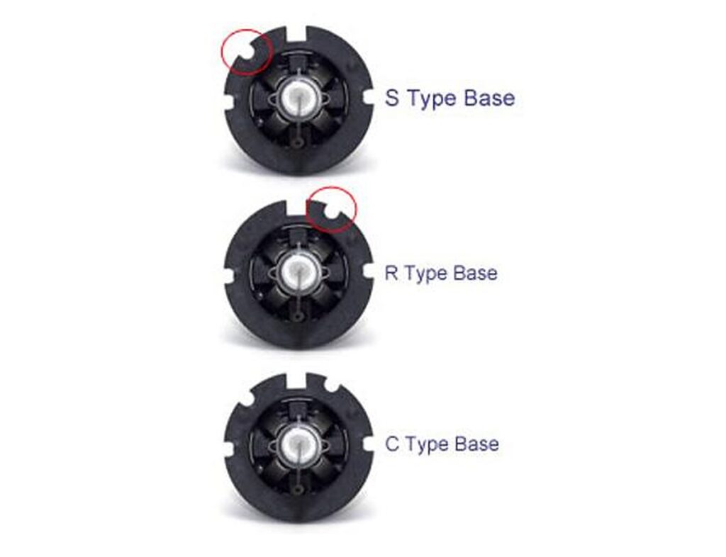
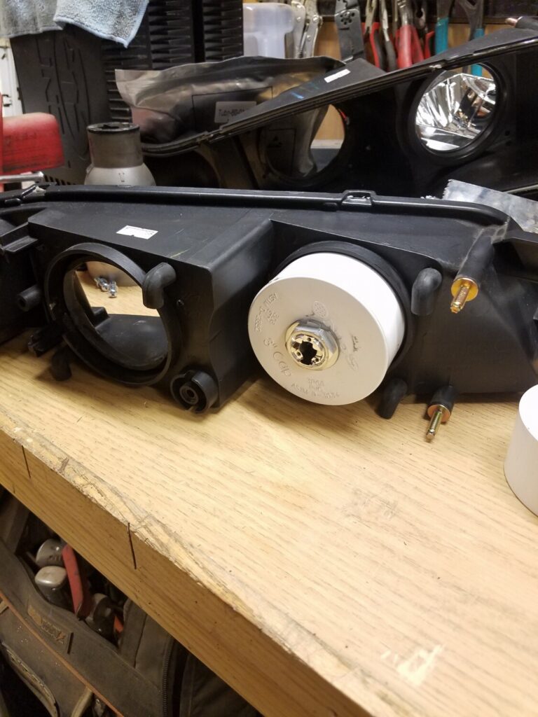
16. Next you will need to convert the parking lamp socket to work on the 1157 Harness. Line up the large tab on the harness with the large notch on the corner housing on the Cefiro. Make note of which notches need to be enlarged to fit the socket in. Take a Dremel with a grinding bit (or Exacto knife) and grind out the notch(s) until you can fit the socket in place. Once this is done, you can install the bulb and socket.

17. Install your H4 bulbs and plug the harnesses in. Then fit the headlight to the car. Bolt down the inner nuts.

18. Next, removed the forward most bolt on the fender nearest to the headlight. Cut a piece of galvanized plumber’s tape that is long enough to reach from the tab on the Cefiro’s to the hole where the bolt for the fender goes. Be sure to align the holes. You will need to find a bolt and nut that will go through the hole on the tab of the Cefiro lamps to secure the plumbers tape. Once you finish that, bolt the plumbers tape into the fender. You may need to push the headlight inwards for the bolt to go in.

19. Once both headlights are secure, take your grill and clean off the bottom section. Affix some heavy duty double sided tap to the bottom section. Set the grill in place and push down to set the tape. You might need to play with the alignment to get it right. Next you can either use plumber’s tape or zip ties to secure the grill to the radiator support frame.

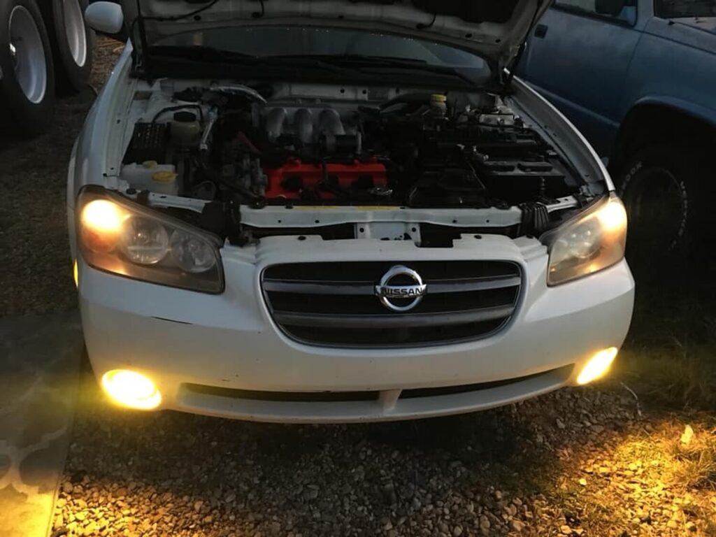
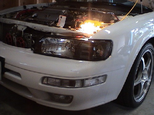
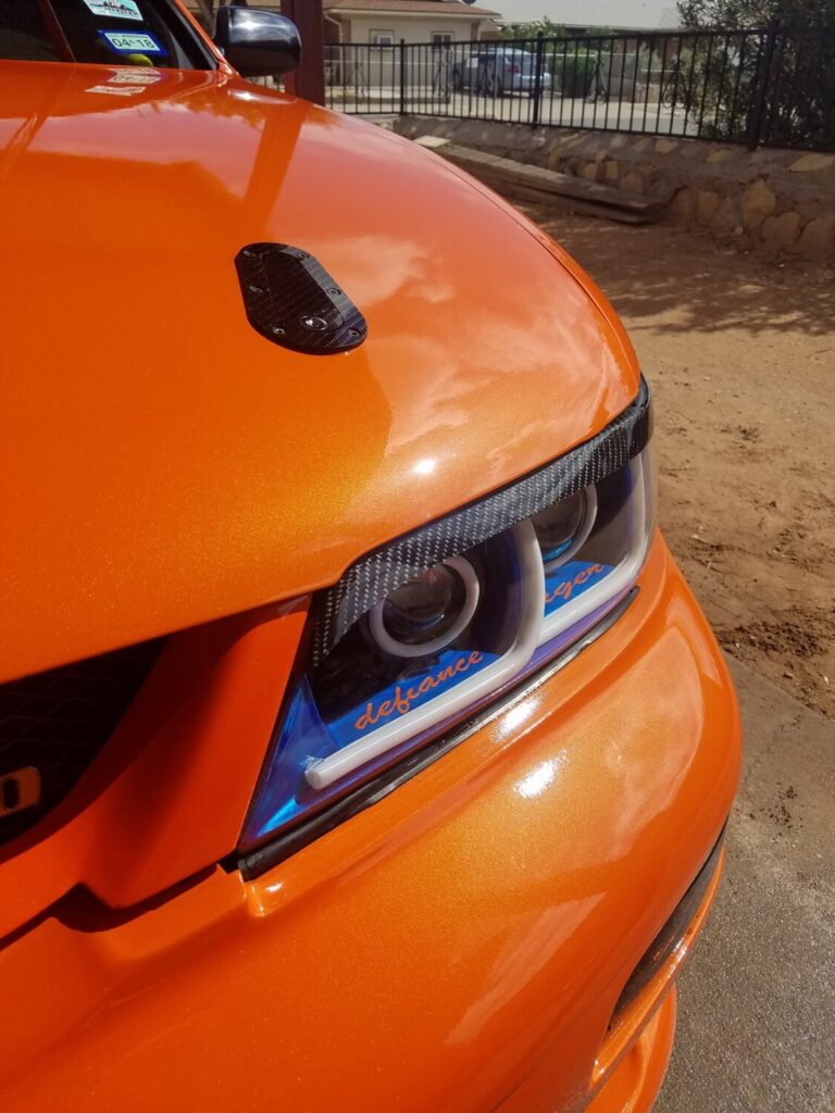
20. Once everything is back on, close the hood and check fitment. Make adjustments as necessary. Also check to make sure all your lights are working properly.

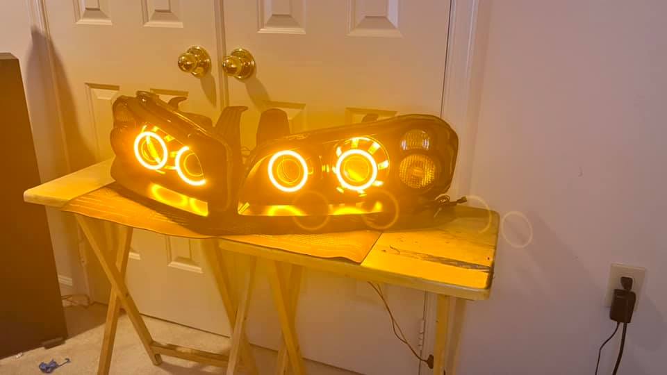
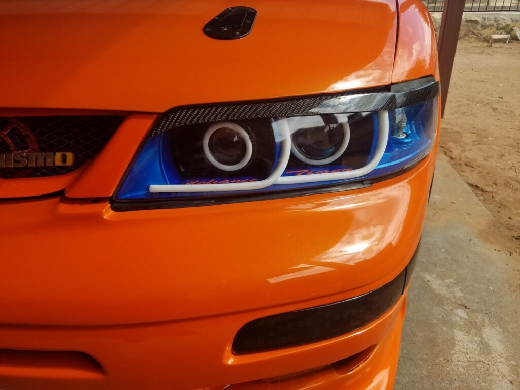
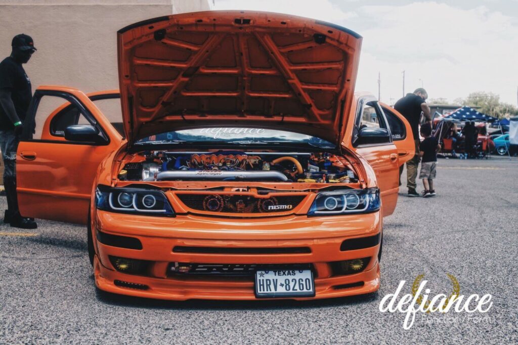
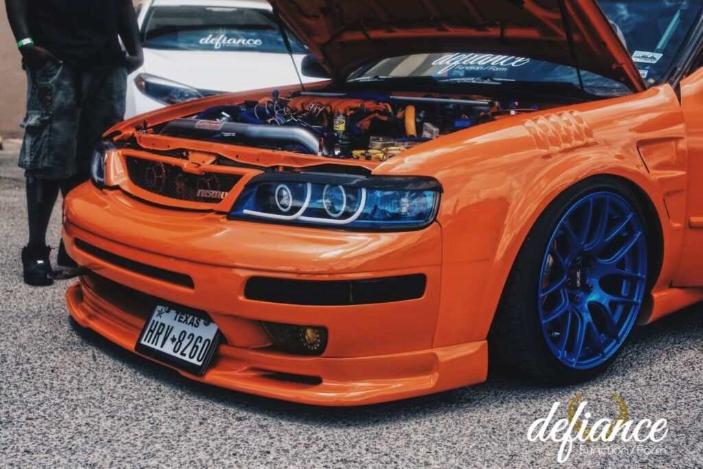
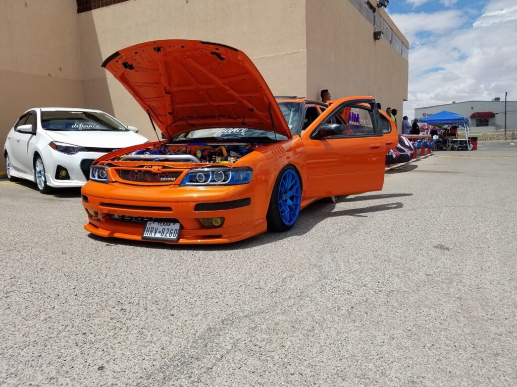
21. You’ve just finished the Cefiro install. Now that wasn’t so bad was it?

Loading

Community Member Credit: gtrrider

Basing our review on a 1995 Nissan Maxima, this application for years has been in great need of a taillight upgrade that did not take away from the car but gave it a very classy and sensual look. Despite the “demand” for the atrocious looking Altezza taillights on the market, Custommaxima has conjured up a way of bringing back the o-so-wonderful Clear/Red Taillights which until now have been sported by only a select few who could get their hands on them. Being that we were one of the lucky ones to have a set on hand we will be testing these new CE Taillights up against an old and sought-after rival “David L Clear/Reds”.

Here is what CustomMaxima (a CustomEnterprise group) had to say about this product, Our customers have been asking for red and clear taillights for their 1995-1996 Maximas and we answered. Now you can eliminate the orange turn signal found on stock taillights and replace it with our new red and crystal clear tails. Sold as a 4 piece set replacing your trunk lights also. The trunk lights need to be replaced as our new lights have a crystal look to them on the clear lens and not the “cloudy white” clear lens found on the factory backup lens. We are sure you will be pleased with the excellent fitment and superb quality of this product. Installation is easy as we include all necessary bulbs and wiring harnesses”. We shall see about that.. read on

Our Take:

With an almost 11yr old car, lighting equipment is certainly looking dated and not appealing to the more modern style lighting equipment. There is noticeable differences with this new system in that there is a reflective diamond-like backing to better illuminate the housing and also provide a better light output when reversing. Not only is the reflective backing more esthetically pleasing to look at but they also provide the brake light area with a much darker and pronounced red glow when the brakes are applied and when the parking lights are illuminated. These new light assemblies are also prepared with a nice but could be better-applied weather-stripping around the outer edge for those times when you do not need water entering your trunk compartment. Most aftermarket taillight assemblies are lacking very important details such as reflective material which is used to draw passing motorists away from the vehicle if you happen to park on the side of the road. This is a safety requirement, and we give a thumbs-up to CE for adding these to their product. Lastly, a key difference between the CE Taillight and the Factory (David L) is that the rear backing is completely redesigned, which may not be for the better.

Pros:

  • Crystal clean look
  • Crisp Red color for brake lights
  • Smooth Installation
  • Chrome bulb standard for turning signal (lights amber)

Cons:

  • Possible seal problem
  • Requires purchasing new bulb for side reflectors
  • Fragile plastic posts may break while securing to car
  • Possible wiring issue, check for breakage in ground before installing.
  • Factory bolts not exactly made to fit these

Application:

  • 95-96 Nissan Maxima’s

Additional Note:

  • 2825 (W5W Bulbs) for side reflectors

Part Number Information:*

  • 95-96 Maxima Red/Clear Taillights
  • 9596RCT
  • $199

Tools Required for Installation:

  • Sockets and Wrenches
  • Short and Long Extensions
  • Flat-head screwdriver
  • Patience

Materials Provided for Installation:

  • 2 Outer Taillights
  • 2 Inner Taillights
  • 2 Mirror Chrome Turn Signal Bulbs
  • 4 Wiring Harnesses

Removal/Installation Process: Outer Taillights

Removal is quite easy with basic tools. Before you begin, we would like to emphasize that the key should be out of the ignition before removal/installation with the parking/driving lights in the off position. Going against this advisor could lead to electrical short, or much worse. ALWAYS CHECK ALL POWER IS OFF BEFORE WORKING!

To begin locate the tabs which hold in the trunk lining to the body of the car, remove these with a flathead screw driver, they should come out fairly easily. Remove both side linings to give you space to work on the taillights. When removed they should expose to you the rear end of the taillight housing, locate the four(4) bolts on each end. Two of the 4bolts are hidden underneath the hanger holding the wiring harness after removing the yellow wire hangers from the inner two(2) bolts. Disconnect all wiring from the back of the housing and proceed to remove. Removing the taillight itself is quite the task, so my suggestion to you is to work each corner one at a time pushing as hard as you can from the inside out without damaging anything.

Installation is the reverse of installation, but we will not be using the backing plate of the OEM taillights, we are given a new harness which for some very strange reason has a different sized side marker bulb then what the factory comes with, which we aren’t supplied. When mounting the new CE assembly make sure to keep watch of surrounding seal so that it seals tightly into place for water not to reach inside your trunk compartment. Although possible it is very hard to maneuver the very loosely applied weather-strip to seal properly, I would recommend laying the light in place, and then pushing in the strip while someone secures the screws (factory screws are not exactly made to fit on these) so we would recommend CE supplying new bolts/washers to fit these. Make sure not to over tighten these bolts to the assembly as they are very weak and can easily break if too much pressure is applied *hint*strengthen posts*hint*.

Removal/Installation Process:

To begin locate the four(4) bolts on each end of the tail light, unbolt all and disconnect all wiring from the back of the housing and proceed to remove. These lights are very tight and uneasy to manage, so if you can try and wedge a wrapped flat head screwdriver between the trunk and the tail light and slowly pry the two apart. Sure enough, the light will slowly come apart from the trunk and you are on your way to replacing the new CE light in its place. Installation is the reverse of the removal, but as with the outer lights we will not be using the factory backing plate, but the supplied CE plate. Final Product: Make sure all mounting points are secured properly, all harnesses connected fully, turn the lights on and enjoy.

Loading

Community Member Credit: maxilvr06

This page is a How to on clearing out that ugly orange blinker lens within the 02-03 maxima headlight housing. If you choose to use a clear lens (and not just leave the lens out) on your headlight, I suggest you buying a package of malibu 11 watt sealed beams (P/N: ML11P2) found at home depot in the outdoor lighting section. They are shown below:

Materials Needed:

  • 10mm Socket Wrench
  • 1 Average Phillips Screwdriver
  • 1 Small Phillips Screwdriver
  • 1 Small Flat Head Screwdriver (or Something Else Small and Flat)
  • Wide/Flat Screwdrivers (as Many as Needed)
  • Dremel Tool With Cutting Wheel and Fine Grit Sanding Attachments Oven
  • 1 Cookie Sheet/Baking Pan
  • 2 Old Towels
  • 2 Malibu 11 Watt Sealed Beams P/n:ml11p2 (Found at Home Depot in a Pack of Two in the Outdoor Lighting Section)
  • Channel Locks
  • Paper Towel

Instructions:

1.) Remove headlight from car by using a 10mm socket wrench to remove the two screws attached to the upper radiator support and pulling sharply.

2.) Unplug one grey harness leading to the low beam and unplug the blinker and the high beam bulbs by twisting and pulling out.

3.) Once the headlight is removed from the car, remove all the bulbs and the ballast from it:

-use an average sized phillips screwdriver to remove the three silver screws holding the ballast to the headlight housing

-unplug the harness connecting the ballast to the headlight housing by inserting a small flathead screwdriver (or something else small and flat) into the opening pictured below to release it while pulling

-disconnect the large red/orange wire from the anchor point by squeezing the tip end together and pulling through

-remove the clearance bulb,
-remove the black plastic cap covering the HID bulb

-twist the harness and pull out to reveal the bulb.

-After you get the bulb disconnected, remove it by pinching the two metal pins together and lifting upward giving you access to it. (all the attatched harnesses and plugs will be fine in the oven)

Here are what the bulb and ballast look like removed:

4.) Remove three very small screws from the backside of the headlight housing (two are located on the blinker side of the headlight, and one is just above where the ballast is; circled in red in the picture at the top of the page)

5.) Take an old towel and wet it, then put it on a cookie sheet or some type of baking pan so that the housing will not come in contact with hot metal while in the oven.

6.) Set the headlight on top of the wet towel face down (no need to cover the housing with the towel) and bake it for 20 minutes in the oven at 210 degrees.

**DANGER! Do NOT let any of the plastic parts, including the harnesses come in contact with any part of the oven or the metal pan! It could melt!**

7.) After taking the headlight out of the oven, lay it on an old towel and put the headlight on your lap while sitting down so you can get a good grip on it.

8.) Using a wide, flat screwdriver, gently insert it in between the black plastic housing and the clear lens where ever there is a gap. (i started at the top)

9.) With the screwdriver inserted still, slowly move it around the housing lifting the black plastic part up and try to pry the tabs up as you go. You can also use a couple other screwdrivers and just wedge them in where the tabs are so that you can pull apart the housing without having the tabs latch again on you.

10.) Be extremely patient on this part and try not to damage any of the plastic. (because it can be quite pliable after they’re baked) Once you get a bit of a gap all around the top of the housing, get a good grip and, without breaking anything preferably, slowly pull it apart. (the sealant will still be very sticky, so if you need to, you can put it back in the oven for 5 more minutes to make it a bit softer)

11.) When pulling apart the housing, try to release as many as the bottom tabs as possible for more ease, but after you get the top half disconnected, it should be pretty easy to pry apart the rest of the housing.

12.) When taken apart, it will look like the picture below. Remove the orange lens by simply snapping it out toward you from the three little tabs. (be very careful on this part though. The tabs are very small and will probably be very easy to break if too much stress is applied to it)

13.) Center the orange lens over the malibu housing as best as possible, and use a permanent marker to trace it onto the malibu lens.

14.) Using a dremel with a cutting wheel attachment, carefully cut the lens out of the housing. (try not to get too close to the circle you traced. the cut doesn’t have to be perfect and you’ll see why in the next step)

15.) Swap attachments on your dremel to a fine grit sander type and go to town sanding down the lens until you get a perfect fit. I suggest doing several trial fits before hand, because in my case, the circle i traced was a bit too small and i ended up using rubbing alcohol to remove the black circle i traced so that it wouldn’t show through.

16.) Snap the clear lens in the same way you took the amber one out, still being careful to not break one of the small tabs.

17.) Assemble the headlight again as best you can and bake for another 10 minutes at the same temp.

18.) Once the sealant is softened again, take your channel locks and put a paper towel inside of them (so that you don’t scratch the plastic) and go around the entire housing squeezing the lens back on using the channel locks. Make sure that all the tabs are attached firmly in the end.

19.) Re-assemble the entire housing and install it back on your car in reverse order and enjoy! (don’t forget the three little screws around the housing though, because i did!)

The results are great!

This is a comparison between the cleared headlight and the stock one. A pretty big difference if you ask me..

Loading

Member Credit: yellow_cake

Hi folks, just thought I’d share my retrofit project on my 99 Maxima.

Components:
– Used Depo headlights.
– G37 sedan projector.
– ’13 Cadillac SRX semi-clear lens.
– OEM G37 shrouds.
– Denso Slim ballasts.
– Osram CBI 66240 bulbs.
– Nichia Superflux white LEDs.
– exLEDs reflectors for superflux LEDs.
– Custom wiring harness + DRL & headlight controller.

Mounted using the JNC method, giving minor rotation and height adjustment on top of the factory reflector adjusters (vert + horiz).
For more info about the JNC mounting method: http://www.hidplanet.com/forums/show…model-pictures
Name: DSC_6315_zpsniwiyhzy.jpg Views: 458 Size: 198.3 KB

OEM G37 sedan shrouds fitted.
Name: DSC_6424_zpsy86jetgf.jpg Views: 412 Size: 156.0 KB

After cutting the container, I used lots of JB weld to secure it into place.
Not shown, but there is also a bunch of epoxy around the inside for added strength. For that I used a self-mixing syringe type clear epoxy.
Name: DSC_6302_zpscv6dde42.jpg Views: 357 Size: 146.1 KB

Here it is, fitment with the reflector mounted into the housing.
The empty containers were from workout supplements; different colours, but both were identical in size.
Name: DSC_6311_zpst4jlgrmj.jpg Views: 336 Size: 134.6 KB

I used a sheet of balsa wood for the base, with some chrome vinyl for the front edge which will be visible.
The LED were secured into the reflectors with epoxy; the reflectors secured to the base & one-another with clear epoxy.
Name: DSC_6274_zpsvewxgibc.jpg Views: 357 Size: 212.9 KB

Home-made resistor array, clear-coated after everything was soldered to prevent the copper from oxidizing.
Name: DSC_6440_zpshiwqmqhy.jpg Views: 350 Size: 120.1 KB

Name: DSC_6276_zpsiucgpwtx.jpg Views: 335 Size: 186.8 KB

Epoxy’d the DRL base into place.
Name: DSC_6431_zpsypfghzkc.jpg Views: 394 Size: 176.0 KB

Cutout the top cover, also made from a sheet of balsa wood. Showing the bottom view where the chrome vinyl wraps around.
Prior to mounting, I spread epoxy all over to prevent the edges of the vinyl from lifting.
Name: DSC_6433_zpsxfnfvr4t.jpg Views: 380 Size: 153.4 KB

Epoxy’d the top cover. The reason I used chrome vinyl is so that the DRL assembly flows well with the rest of the headlight.
Name: DSC_6445_zpsrx920vb5.jpg Views: 350 Size: 163.7 KB

Close up of fitment.
Name: DSC_6446_zpshfidfuvi.jpg Views: 328 Size: 192.2 KB

The Denso slims had the short cords, this would be problematic for most retrofits…
I extended the wires while making the ballasts D2S/AMP hybrid. This will make headlight removal easier as well.
Name: DSC_6468_zps709gl5yn.jpg Views: 324 Size: 177.3 KB

Soldered + adhesive lined shrink tubing. Notice how the solder joints offset one-another, good practice in case the joint or insulation fails (which it shouldn’t, lol).
Name: DSC_6469_zpskeu7atqn.jpg Views: 350 Size: 186.2 KB

Terminals crimped on.

Ooooohhh, aaaahhh… I’ll be potting the ballasts as well.

Wires fished out through a rubber grommet.
Here’s the wiring setup: The one loom has the DRL + solenoid wires, the other has the ballast cord.
Name: DSC_6476_zpsd1a8bwpp.jpg Views: 354 Size: 114.0 KB

Cap screwed on, sealing the back from dust/water.
The 3-pin connector wires: solenoid positive, ground, and DRL positive.
Name: DSC_6474_zpsotdng89f.jpg Views: 335 Size: 112.5 KB

The rubber grommet at the bottom.
Name: DSC_6477_zpsiifryxrf.jpg Views: 369 Size: 122.5 KB

Headlight completed!
Name: DSC_6482_zpsdcuxr7mf.jpg Views: 315 Size: 176.7 KB

Here’s the custom DRL controller + headlight controller.

The DRL controller has a dual brightness mode via an external PWM (ebay). Also, I’ve made it so engaging the e-brake will disable the DRL, just like the stock DRL. This will give me the ability to pull the handbrake up one click and have the DRLs off if I need to be stealthy, lol.

On the right is the low+high beam controller. basically it’s a delay off circuit. Meaning, if the headlights are on and then turn them off, it will take about 2 seconds to shut off… I did this mainly for flashing while the headlights are off. This way it’s not flashing the ballasts as they remain on in between flashes.
Name: DRL-headlight_controller_zpse6mnqqvz.jpg Views: 360 Size: 201.0 KB

Ebay PWM at the bottom.

Potted the Denso ballasts.
Name: DSC_6484_zps9upsmorf.jpg Views: 381 Size: 209.9 KB

Made a 9004 “connector” out of an old bulb. Removed the bulb and soldered wires onto the pins, then filled it with potting compound.
Name: DSC_6487_zps8omya040.jpg Views: 335 Size: 60.8 KB

Eventually I plan on making an Arduino controlled DRL/headlight controller, it will have a fancy aluminum housing… For now, I’ve got the current setup wrapped in electrical tape… yea, it looks like a grease job, LOL.
Name: DSC_6488_zpst4pfmosu.jpg Views: 384 Size: 104.4 KB

Installed.
Name: DSC_6506_zpsj2vc0yas.jpg Views: 350 Size: 171.1 KB

DRLs on:
Name: DSC_6499_zps1cqiqgqz.jpg Views: 442 Size: 436.9 KB

LEDs are dimmed when parking lights come on.

Low beams on:
Name: DSC_6502_zpsldgvtz5p.jpg Views: 345 Size: 182.5 KB

I don’t have output pics at the moment, but I’ll get them in the next few days.

Loading

Member Credit: Metal Maxima

Alright, as my final HOW-TO on the .org, I am going to be detailing how one can black out your headlights and add the newly coveted Audi LED effect to your headlights. Without much adeiu, let’s begin!

ITEMS NEEDED:

  • Flexible LED strips from Oznium ($40)
  • Amazing Goop from Home Depot ($4)
  • About 5 hours…this is actually a pretty quick mod

STEP #1
Remove headlights. I am not going to detail this, there are two screws to remove that are exposed at the bumper level then just pull out…HARD.

STEP #2
You’re going to need to remove some hardware from the headlights before beginning. All rubber components, bulbs, and any screws that will come out. One universal item the bulbous thingie that was a beotch to remove in the previous step.

STEP #3
Obtain a flat baking sheet and a large towel. Wet the towel so it’s wet, but not dripping wet. Drape across the entire length of the sheet. TEST FIT THE SHEET WITH THE HEADLIGHT IN POSITION. Once you’re comfortable with the fit, preheat the oven to 250F. Place the headlight facing UP.

STEP #4
Bake for 10-12 minutes, ONE AT A TIME. Feel free to nervously pace the kitchen floor. *DING* That’s the sound of opportunity! Take your headlight out. I recommend using leather gloves, you’ll need the dexterity. Start by removing the two screws where the bulbous thing is…they are easier to remove once the adhesive is at working temp. Pry your headlight apart by using a flathead screwdriver to pry the mechanical attachment points open. Then pull…I only did 10 minutes and pulled…hard.

STEP #5
Remove the chrome components from the body. Here’s a shot of the only two screws for the 5th gen. The 5.5 gen will have more, sorry, I have limited pics of the 5.5gen. NOTE: Your lens portion will need to be warm for the 5th gen shroud to be removed; this allows proper expansion…believe me, it ain’t coming out otherwise.

You’re going to want to tape the chrome sections you want to retain. This is actually easier then it sounds. Use small pieces when going around the corners. TIP: Take the tape and slowly walk it across the contours…you will have 0 difficulties if you do so.

STEP #6
Paint using Duplicolor’s High Temp Engine Enamel. Do 3 coats; two light coats at about 12″ distance, very quickly. Do a third “wet” coat; you can do multiple light coats, but I’ve used close to 100 cans of spray, so I have an unfortunate familiarity with how it behaves. Allow 2 hours cure time, then peel away.

STEP #7
Cut your LED strip to size and attach it using the double-sided tape included. One the 5th gen, you’ll use 21 LEDs. The 5.5 gen is considerably more, just cut to size. NOTE: The array on the strip is in denominations of 3, so you must have a multiple of 3 in order for the full length to light!!! (i.e. 36, 33, 30, etc.)

STEP #8
Drill a small hole to allow for wire passage…I did mine as seen here on the 5th gen…I recommend going toward the turn signal as it is less readily seen below:

STEP #9
Now this is what I consider to be the hardest step. In order to properly reseal, we need to reuse the existing sealant. SO, back in the oven we go…ONLY PLACING THE LENS AND BODY IN THE OVEN. Do so at 250F for 10 minutes. You’re going to want to leave the body face up as the channels will likely contain the largest portion of sealant. Remove when the adhesive is glossy, meaning it’s at working temp.

STEP #10
While everything is hot, QUICKLY reassemble. Be confident, you can do it. You’ll need to do this for the proper seal. Push the body and lens together, making sure the mechanical tabs properly latch. Route the wire behind the lens shroud, you can drill your own hole or use the vent line aperture.

STEP #11
*WHEW*, ok, so you got the lenses probably 80% sealed. Time for some GOOP! Add some extra sealant, we’ve done all this work and don’t want to blow it now.

STEP #12
FIRE IT UP! Test with a 9V to enjoy the awesome effect. These things are BRIGHT!


Loading