Credit: shawn’s maxima


![]()


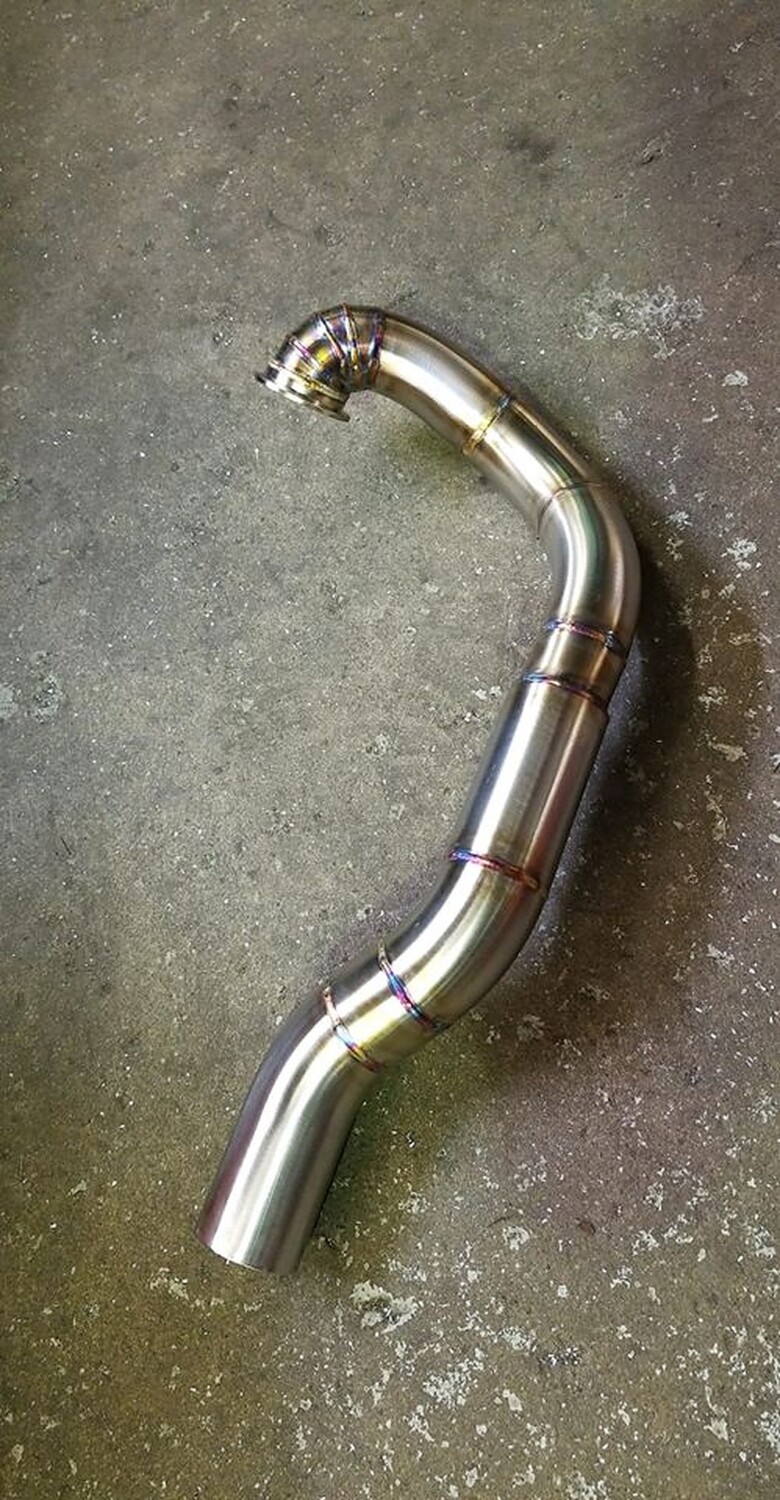
Credit: Rene Saran
This setup is 2″ from the eBay headers, stepped to 2.25″ into a slip connector that goes to 3″ all tig welded stainless a d vibrant everything. The work was done by Centerline Motorsports.


![]()


There are many types of intakes out there on the market (including ones made out of PVC piping). They come in 3 popular piping sizes (3″, 3.5″, 4″) and models (SRI, Cold Air, Cooler etc…).
Which size are you likely to select for your performance modding?

![]()

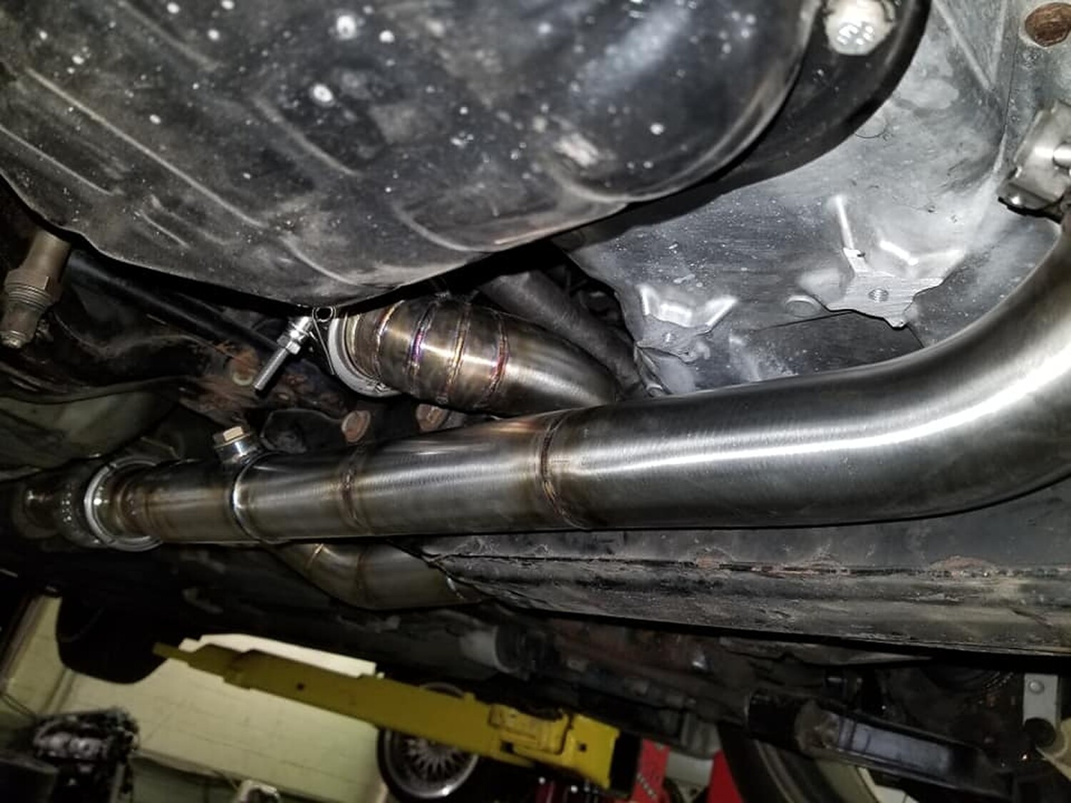
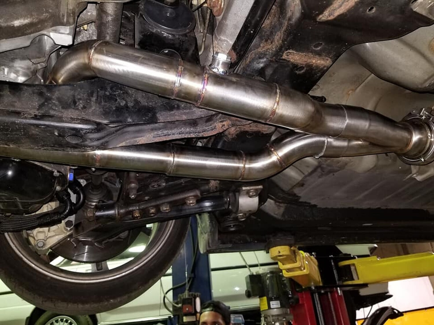
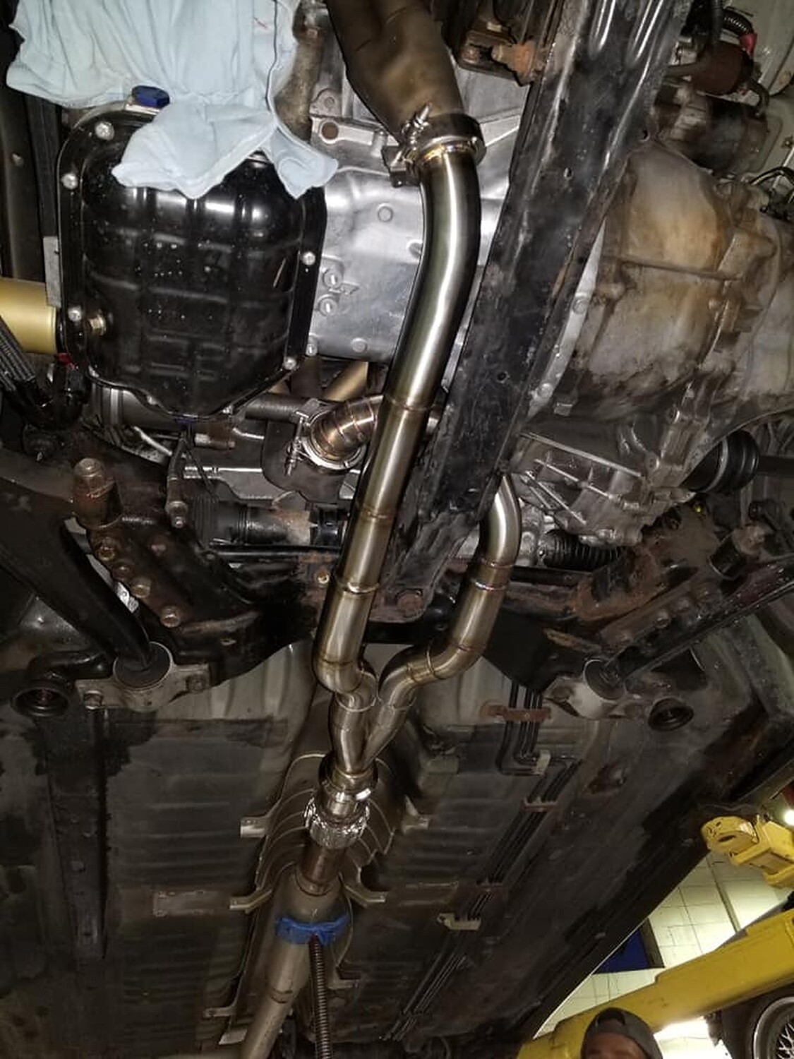
Member Credit: lowriderman3
Tony Motordyne exhaust installed. This was labeled for the 7thgen Maxima, but fits the 8thgen with just a few very easy twist mentioned below.


![]()
")

Member Credit: Orgullo
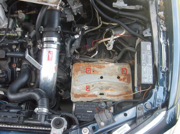
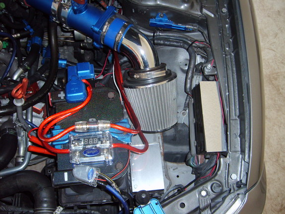
This is the battery relocation for the 2002/2003 Nissan Maxima. However, I’m sure it will work for the other gens too since it’s basically the same. I did this on my 5.5 and my boys 5.5 gen Max.
This set up is for people that already have a aftermarket intake. If you are running the Injen intake, like I was, then you can use it. Using your Injen intake you will need to get another midpipe ( berk, frankencar etc…) and another coupling.
Tools:
Sharpie.
Dremel.
Drill with 17/64 drill bit.
10mm Socket / Wrench.
Screw Driver / Flate head, Phillips head.
Pliers
(1) 17/64th sized bolt.
How To: Relocating your batter and fuse box.
1) First of all turn your wheel all the way to the right.
2) Remove your Intake and next you need to remove your battery.
3) Remove the plastic cover, this will expose the (3) screws holding down
the battery tray. Take those out.
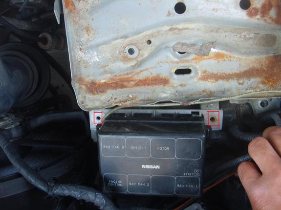
4) After removing the screws you will need to remove the fuse box. It is
held in place by two screws.
5) Looking at the tray you will see that the Positive terminal cable is
attached. Just pinch the zip tie and push it out. You should be able to
pull the tray out.
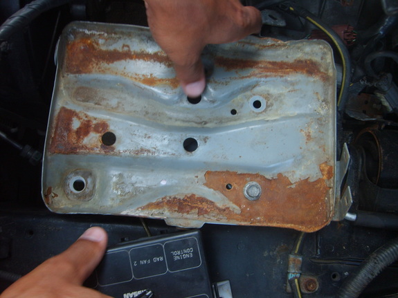
6) When you pull the tray out you’ll see that it has mounting points for the
fuse box, the positive terminal mounts and where the tray mounted to
the car. ALL of these need to be cut off. Use your dremel to accomplish
this. Now is the time for this kid to get his sanding and painting skills on.
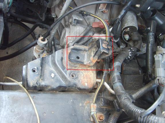
7) Looking at where the tray was you’ll see a raised piece. This needs to
get cut off to make the surface flat. Just use the dremel to cut it off. If
you look close you’ll see small circle’s. This is the tack weld, lightly cut
over that circle and wedge your screw driver and pry it up. Take your
pliers and start turning it in a circle motion and it will pop right off.

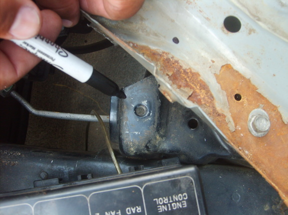
8) Place your battery tray to sit parallel on the mounting point. You will use on of the existing holes to mount this.
9) Once you have it aligned slightly pick up the tray and you’ll see where the other screw will go. Use your sharpie to mark the spot in relation to the tray on the tray. Once this is marked take your tray off and drill out the spot where you just marked. Use the 17/64th drill bit to drill out the spot.
After you drill it out lay it in place to make sure it lines up perfectly. If it does then straight, if not check your alignment and drill it out. This is enough to secure the weight of the battery with NO problems. Do not secure the battery tray down just yet.

Next is aligning the fuse box.
10) Parallel the fuse box and push it snuggly against the battery tray. You will see where the original mounting point on the fuse box was. You are going to use it again. Take your sharpie, mark the spot and move it to the side. Take your drill and 17/64th drill bit and drill out the hole. Don’t worry there is nothing there but space. Put the fuse box in place and use your 17/64th bolt to secure it down.

This is what it should look like when you are done.

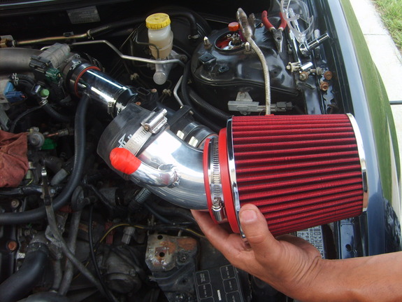
Now turn your INJEN WAI into a CAI. You will need a new midpipe and coupler to make this happen.
You have all this space to work with. Up underneath is open space. You will take your dremel and cut out a triangle shape, smiley face, whatever you like. J/K cut out a circle large enough for your piping to go through.
1) DO NOT go beyond this red line, you will be cutting into the frame. I found it easier to use a drill and drill holes, then take the dremel and cut the lines. Take your pliers and catch a corner and start turning in a circle. It will role up and come out easier. You can take your dremel and clean up the edges when you have finished.


2) Assemble your intake set up. Coupling, new midpipe, coupling, MAF, coupling, Long elbow of the Injen intake, coupling. You will assemble the Injen midpipe and filter inside the fender.

3) The Injen midpipe has a line for the vacuum. You will need to block this. I used some gasket making material. Also, on the long piping of the Injen there is the mounting point that you will need to cut off. You don’t have to but it looks better.
4) Place your intake set up in place.
5) After extending the piping into the fender you will need to pull the fender plastic towards you. You will see the piping coming down. You will then connect the Injen midpipe and filter to the piping coming in. This completes your intake set up.

note: Make sure all your couplers have been tightened down. Also, make sure you hook the vacuum line back up.
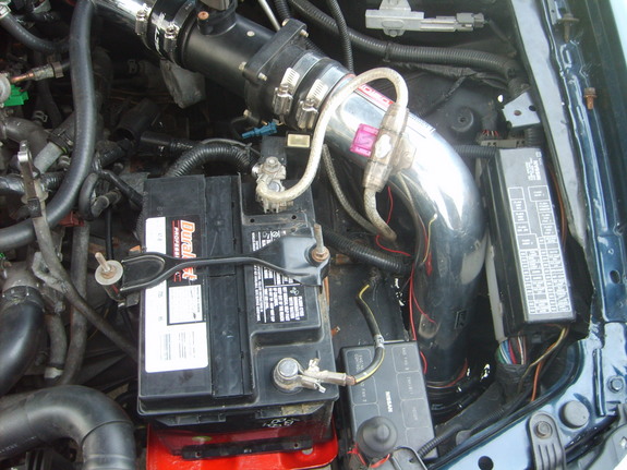
6) Everything is finished. Put your battery tray back on, secure it in place.
7) Put your fuse box in place and bolt it down.
8) Connect your battery negative and positive and your set.
It should look like this!!!


Running it short ram.
![]()

Member Credit: Whore-Jay
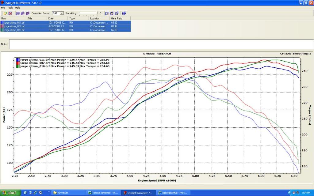
The SSIM (Secret Sauce Intake Manifold) was created years ago by member SR20DEN. This involves cutting the shelf out of the main chamber of the upper intake manifold and removing the VIAS assembly. This will still lose a little low end power, but the gains in the top end are very noticeable. It’s definitely a modification that is worthwhile.
Below are the results of 3 different Intake Manifold setups. All runs done on the same dyno with the same AFR (tuned for 13) and around the same temp. Stock (runfile11), SSIM (runfile10), VIAS delete (runfile7). Your constructive input is welcome but I am not here to argue about any of my results, this is what I did and that is what I got end of story so please no flaming. Enjoy!!!
Stock IM with functional VIAS.

Stock IM with VIAS deleted, NWP Block plate used.

SSIM with VIAS deleted, NWP Block plate used.

All three HP overlay.

All three TQ overlay.

All data combined.
My thoughts on the SSIM vs Stock.
My thoughts on the VIAS delete vs Stock.
The verdict….. Its really just up to what you want to drive with, I am choosing the NWP Block plate with an unmodifed IM for now.
*Mods*
![]()
 Setups")
This is a gallery of Secret Sauce Intake Manifold (SSIM) Setups. The SSIM (Secret Sauce Intake Manifold) was created years ago by member SR20DEN. This involves cutting the shelf out of the main chamber of the upper intake manifold and removing the VIAS assembly. This will still lose a little low end power, but the gains in the top end are very noticeable. It’s definitely a modification that is worthwhile.


![]()
")
Member Credit: Fezzik
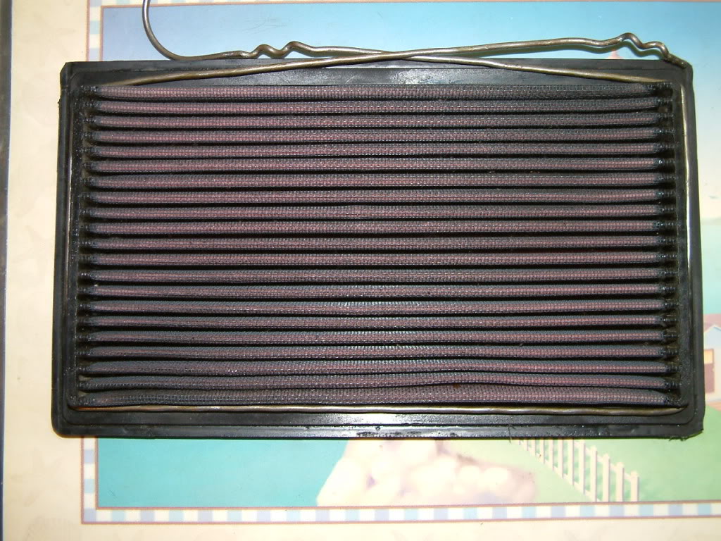
Hey guys. I was really interested in the Ghetto Air Box (GAB) but did not want to destroy the filter holder (>65 dollar value according to Dave B) So I thought up a way to create the same thing without cutting part of the holder off. This may have been thought up before but I didn’t know about it.
First you will need the following:
The basic tools, a hanger (I used a thick gauge one), black sharpie, and of course your filter (Mine is the K&N one):

Unwind the hanger as shown below:

Straighten up the hanger as best as you can:

Now you want to center the hanger at the bottom of the filter and mark on the hanger where the side of the filter is like seen in this picture below:

Now bend the hanger in a 90 degree angle like so:

Do the same thing for the other side (Make sure the hanger is fairly flat against the filter):

Now mark the top part of the hanger where the top part of the filter is and bend those in at 90 degree angles too:
Now move in about 2-3 inches and bend the hanger away from the filter like seen in the picture. Then move out about 1-2 inches away from filter or about 0.5 inches more than the distance from your filter (where the hanger is at) to the edge of the opening that’s near the headlight (yeah this is a little confusing) See two pictures below for a better understanding.


Stick the filter in and then mark the hanger hangs back out like seen:


After marking the hanger go and bend it so it goes around the lip of the opening of the air box like seen below:

The final product:
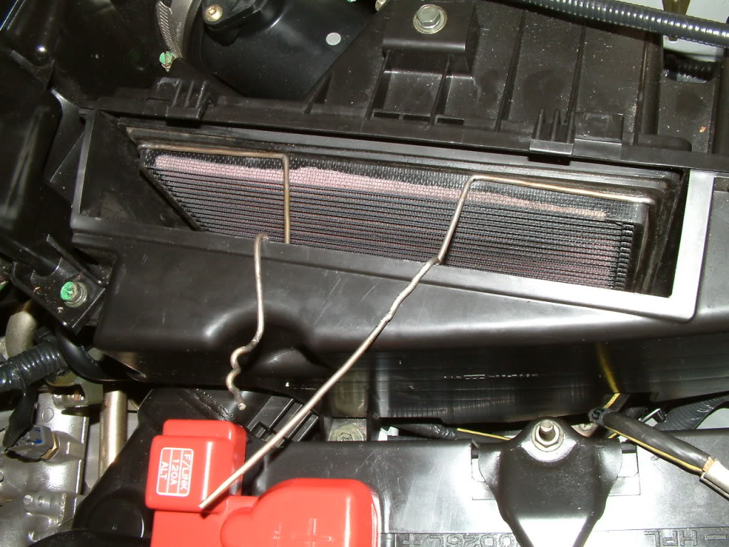
and a close-up of it

I haven’t cut the ends off yet. Another thing I am going to do is add electrical tape around the hanger just so it looks better and some extra around the area where the hanger is now hooked onto the air box opening. But I’d figure this will help those out there that are wanting to do this mod but not wanting to cut their filter holder or just have the really ugly duck tape holding it in.Butt feeling of this is that it feels like the car can breathe a lot better and seems to have better response even in low end.
Additional Photos:


![]()


