Tag

Intakes, Headers & Exhaust

Browsing

Member Credit: Ken Rosengren

FAQ

Q) What does a knock sensor do?

A) A knock sensor is a specially designed listening device for car engines. It listens for engine knock, or detonation (pinging). Detonation can be very bad for an engine and is the result of the fuel/air mixture exploding too quickly instead of burning evenly and rapidly. This is due to either bad fuel, ignition timing which is too high, or built up carbon deposits in the engine (which increases the compression ratio). The sensor is small and consists of a piezoelectric sensor that listens for knock by detecting pressure. It is very sensitive and can be considered worthless if dropped. The vibrational pressure is then converted into a voltage and sent to the ECU for evaluation.

Q) How do I know if my knock sensor is bad?

A) Symptoms of a bad knock sensor include a sluggish engine, poor acceleration and poor fuel economy. Knock sensors rarely fail outright and more often get “soft” over time and cause false signals to be sent to the ECU, which thinks the engine is knocking when it’s really not. Thus, the ECU will reduce the ignition timing to the engine. The knock sensor on the VE30DE is prone to corrosion of the terminals and harness connection. This is due to the harness weather seal getting brittle and cracking, allowing moisture to seep into the harness from the rear and corrode the terminals. This creates a poor connection and faulty voltage readings to the ECU.

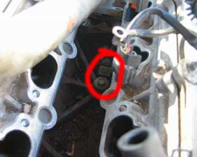
Q) How do I test my knock sensor?

A) The knock sensor voltage can be checked through an electrical harness located right above the thermostat housing (where the lower radiator coolant hose attaches to the engine). It is a gray connector with an orangish red cap with two wires. Unplug the connector and attach a multimeter (or voltmeter) to the lower harness (the male connector). The wire for this connector should go left and underneath the intake manifold. Check the front most terminal (see pic) and ground out the negative point. You must have a multimeter than can measure more than 10 M ohms. Continuity should exist. This method is per the Factory Service Manual. NOTE : Knock sensors should be considered regular maintenance items. If you have over 100K miles and have never replaced the knock sensor, you can probably consider it bad.

Q) What parts will I need?

A) For knock sensor replacement only, here are the required parts:

-Normal hand tools (8, 10, 12mm sockets, long extensions, 14mm open-end wrench, large adjustable wrench, torque wrench, Philips screwdriver, 6mm hex key socket (I THINK this is right, check the size of the intake plenum hex bolts first to see if it fits before you start)).

-Coolant and distilled water (about a gallon total)

-Knock sensor PN 22060-30P00

-Knock sensor sub harness PN 24078-30P00

-Throttle body gasket PN 16175-53J00

-Intake plenum gasket PN 14032-97E00

-2 Intake manifold gaskets PN 14035-97E00

-Liquid gasket which is impervious to coolant (high-temp)

Q) What are some other things I could do while I’m in there?

A) Since you will be draining some coolant and releasing the fuel pressure, here are some things you should think about doing (though not required):

-Replace all fuel lines with rubber fuel injection hose (don’t get normal fuel line since they are not reinforced for high-pressure fuel injection systems).

-Replace all coolant hoses (radiator hoses, bypass hoses, throttle body hoses, there are a lot of small ones that are very difficult to get to normally, this is your chance to do it easily)

-New vacuum hoses (you’ll need at least 8 ft I believe, there are a lot of small ones)

-Fuel injectors: Might want to get them cleaned and install new o-rings and grommets

-Fuel filter, since the fuel pressure is released, why not?

-Port match intake manifold/plenum and throttle body

-New coolant temp sensor

-New PCV valve

-New thermostat

Q) I’ve never done major work on a car. Can I do this successfully?

A) Replacing a knock sensor isn’t necessarily hard work, but it is time-consuming. As long as you think the project over beforehand and label everything you disassemble, you should go fine. The worst thing that can happen is you end up with a loose hose somewhere or have an intake or coolant leak.


Now the fun part, actually doing the job! These procedures were produced from my 93 SE 5spd. If you have an auto, you might not have as many vacuum lines to disconnect since the 5spds have the power valve and purge canister.

Release fuel pressure

The FSM states that to release the fuel pressure, you need to remove the fuel pump fuse located in the interior of the car under the panel by your left knee when you’re sitting in the driver’s seat. Crank the engine up, let it die, then crank it a few more times until it doesn’t start. Then take out the key and replace the fuse.

Drain coolant

On the bottom right side of the radiator is the drain cock (plastic t-handle with a small clear rubber hose hanging down). Open the drain cock and allow about 3-4 quarts of coolant out. You don’t need to drain the entire engine since the intake manifold only holds a small amount of coolant, and this is the first part to drain since it’s highest on the engine. Remember to shut the drain cock!

Disconnect battery

Very important! You will have open fuel lines, so one spark could start a fire! Remember to disconnect the negative cable first.

Disconnect intake and air box

-Unclamp the 4 latches on the air box as if you were changing your air filter

-Loosen the throttle body air intake tube clamp

-Unclamp the two big rubber breather hose attached to the plastic air intake tube.

-Unhook the two vacuum lines attached to the resonator, then lift the entire air intake unit out and out of the way

Disconnect blow-by tube

This is the small, long metal tube attached to the front of the intake plenum

-Unbolt two 10mm bolts and two rubber hoses.

-Carefully unhook the wiring harness clamps. These are very brittle and if not already broken, will break if you force them! Have some zip ties ready if you do break them
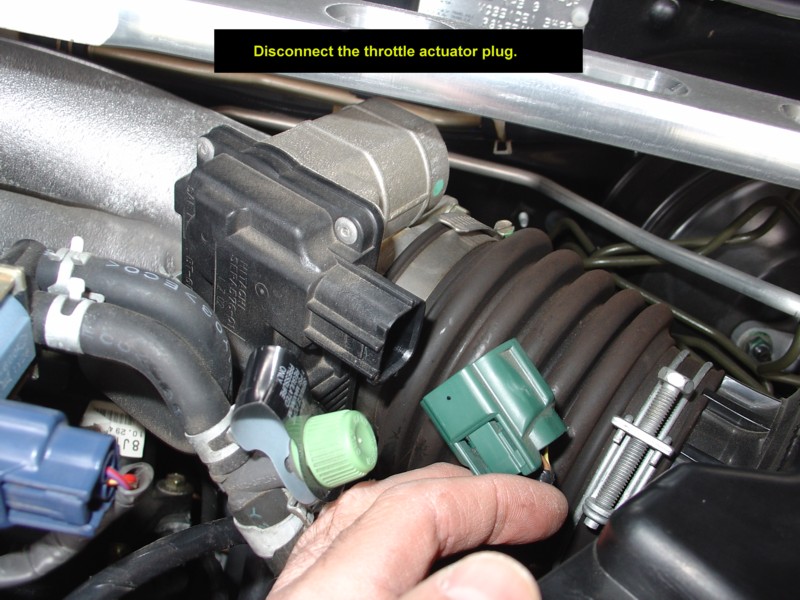
Throttle Body

Just disconnecting the throttle body is the easiest way to do this. You can leave the TB attached but then you must remove many vacuum and coolant lines from it. It’s easiest just to remove it and lay it on the side.

-Remove the throttle and cruise control cables by loosening the left nut with your 14mm open-end wrench (furthest from throttle body, if you loosen the right nut you can change the tension on the cable, not good!). Then remove the cable from the TB bracket.

-Remove a short vacuum hose on the bottom of the TB that connects to the intake plenum

-Remove the 4 hex bolts using a criss-cross pattern and remove the TB

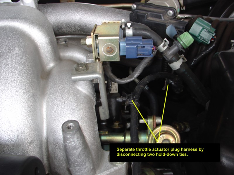
-For added stretch you might have to unclip the TPS harness from its mount
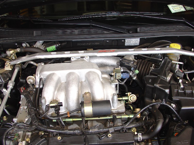
Intake Plenum

-Unplug and remove the three rear coil packs

-Remove three ground straps (10mm bolts) 2 on front of plenum, one on left side *Take a dremel or steel wool or something and clean these ground straps and mounts to get the oxidation off, these need to make good grounds!*

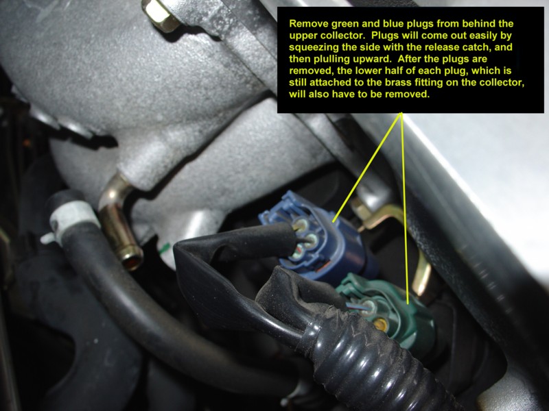
-Remove the vacuum hose from the power valve on the left side of the plenum (N/A for auto)

-Remove the tiny cruise control vacuum hose from the rear of the plenum

-Remove the mid-size vacuum hose on the rear of the plenum that routes to the brake booster

-Remove the mid-size vacuum hose right underneath that (this one meets a metal pipe which eventually winds up at the PCV valve.

-Now, remove the two 12mm bolts that this PCV metal pipe connects to the plenum with

-While you’re down there, remove the two 12mm top bolts of each plenum stiffening plate (only one plate is shown in the picture, there is another to the right by the EGR)

-Take your big adjustable wrench and crack the big nut loose on the EGR valve. Loosen it all the way until it moves freely and you can see a gap between the EGR valve and metal EGR tube

-Remove the 4 remaining vacuum lines by the throttle body location.

-This one’s hard to see, but there are 4 12mm bolts holding on the EGRC valve on the lower right side of the plenum. Two on the right side, two on the back side (one is not visible in the pic)

-Remove the 10mm bolt holding on a metal vacuum line mount on the right side of the plenum, in front of the throttle body. It has a yellow sticker on the mount.

-Now all you have to do is crack loose the 6 hex nuts in a criss-cross pattern and pull off the plenum! If it doesn’t come off freely, hit the “Nissan” part lightly with the palm of your hand. Now, when removing the plenum, make sure everything is disconnected before you rip something off

Fuel Rails

-Loosen the screw clamps for each of the 4 small fuel lines (2 on each rail)

-Remove the fuel “T” line on the left side by removing the two 10mm bolts. Be careful not to drop these down the intake manifold as you’ll have to fish it out of the intake port of the head if you do (speaking from experience here)

-Break loose the fuel lines and be prepared for some fuel to spill out. Have rags handy. Remove the fuel “T”

-Now remove the 4 hex bolts of the fuel rails. Be prepared to gather a plastic spacer and metal washer for each bolt as they will fall and get lost easily. Remember how they fit! Plastic washer on bottom, then fuel rail, then metal washer on top, then bolt.

-Lightly pull up on the rails, when they are loose you can remove the right fuel lines. Do not drop the fuel rails, injectors are fragile and expensive!

-Watch for any loose fuel injector grommets (where the fuel injectors sit in on the manifold). Don’t lose these unless you have new ones ready to go.

Intake Manifold

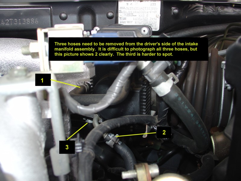
-Remove the left radiator hose and the smaller bypass hose right next to it. You only have to disconnect them from where they meet the manifold

-On the right side, remove the three bolts that hold on the coolant tubes to the right side of the manifold. You may have to pry a bit to get this off as it’s sealed on with liquid gasket.

-Disconnect the coolant temp sensors (big one and small one, be careful as these electrical connectors are brittle, and you’ll have to pry the small metal wire clip to remove it)

-Now crack loose the 4 nuts (not bolts yet!) in a criss-cross pattern, 2 on each side of the manifold

-Now loosen the 6 hex bolts, again in a criss-cross pattern (important, you don’t want to warp the manifold by improper untorquing)

-Make sure you gather the washers that go with the nuts

-Pop off the manifold (you might have to pry a bit)
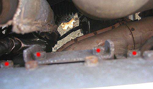
Water Pipe

By now, you can see the knock sensor and the pile of crud in the valley of your engine, but there’s no way to break the sensor bolt loose because the water pipe is in the way!

-Remove the two nuts and washers on the left side (connecting to the water pump)

-Remove the two bolts that bolt vertically down into the engine block on the right side.

-Now, using a LARGE flathead screwdriver, pry the water pipe off the studs on the water pump side and you’ll be able to hold the water pipe up to get to the knock sensor. Much easier than removing the thermostat housing and all those coolant lines on the right side
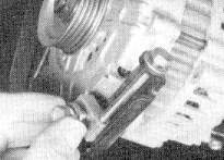
Knock Sensor

Finally, one bolt and it’s off. Clean the contact point thoroughly since any dirt or gunk will make the sensor less effective. Now, put the new sensor in and BE CAREFUL with it. Remember not to drop it or hit it against anything. Even when bolting it down take extreme care, you do NOT want to over tighten it! I couldn’t find a torque figure in the FSM so I just tightened it down until I felt resistance and went about another half turn. My uncalibrated torque right arm says it was about 15-20 lb/ft.

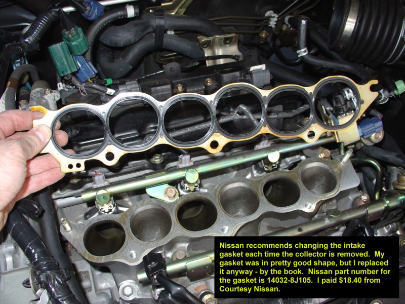
Now it’s time to clan the gasket surfaces on the head, manifold, plenum and throttle body. Use a paint scraper for the best results. A bit a steel wool won’t hurt either. Make sure no debris or anything falls into the intake ports in the head. Also clean off the water pipe where it was sealed with liquid gasket

Installation is in the reverse order of removal. Use a solid bead of liquid gasket on all surfaces. Completely circle around all pipes (on the right side of the intake manifold, the coolant pipes that attach have two pipes. Make a circle around each hole so they don’t leak into each other). Don’t use TOO much liquid gasket though. A thin solid bead is all that is needed. Allow at least an hour for it to dry (by the time you get everything else back together, at least an hour will have passed)

Intake manifold torque for the hex bolts is 20 ft/pounds. For the 4 nuts it is 24 ft/pounds.

Again, torque them in a criss-cross pattern (middle bottom left, middle top right, middle bottom right, middle top left, far bottom left, etc)

Fuel rail bolt torque is 20 ft/lbs

Intake manifold hex bolt torque is 20 ft/lbs. Criss-cross pattern.

Throttle body torque is 15 ft/lbs, criss-cross pattern

Make sure you replace all the plastic spacers and washers correctly when you replace the fuel rails.

When replacing your coolant, fill it up to the top of the radiator cap. Now, carefully open the 10mm nut by the large coolant bypass hose on the right side of the intake manifold (by the two pipes and the coolant temp sensors). This is a purge valve and releases the air in the system as you fill it up.

Start it up and check for leaks. When all done, take it for an easy test drive quick around the block then check for leaks when you return. On the first real drive, drive slowly as if you were breaking the car in. The metal manifold gaskets need a complete heat cycle to seal correctly. You don’t want to risk doing this over again! Then disconnect the battery (negative first, then positive) and let it sit overnight. In the morning, enjoy your newfound VE power!

The Rubik’s Cube is the most popular puzzle on the World. Learn how to solve it with the easiest method.

Loading

Member Credit: Bryan Tisch

Below is the distributor hold-down bolt which resides under the distributor, you can see the sun shining on it in both pictures. To change the timing:

  1. First obtain a timing gun (normal or one with the advance feature)
  2. Make sure the engine is warmed up and running at a normal idle level [during the whole procedure].
  3. Hook the #1 cylinder up to the timing gun and the two terminals to the battery.
  4. Check your current timing by aiming the timing gun near the belts on the right side of your car directly on the crankshaft pulley. There are 7 tick marks, starting from the left (closest to the windshield) 0, 5, 10, 15, 20, 25, 30 degrees. The first tick mark is technically supposed to be orange, but might be covered up from dirt.
  5. There is a timing indicator (I call it an arrow) which indicates where your timing is when the light from the gun is flashing on it. If you see the arrow on the middle mark (4 from the left when standing at the right front tire), then your timing is right at 15 degrees.
  6. Remove the “ECCS” cover.
  7. Obtain a 9 mm socket with an extension and loosen the below distributor hold-down bolt.

    a. Be careful to keep the wires away from the accessory belts or cooling fans
    b. Do not take the screw out, only loosen it a little.

  8. Once the screw is loosened, put your hand on the distributor and slightly turn it to the right (advancing). Have the nut on the distributor snug enough where it stays in place for fine tuning.
  9. Next, check your timing with the gun. I recommend going with 20 degrees, which is the 3rd tick mark from the right (5th tick mark from the left). 18 is also a good number and you can adjust accordingly for it.
  10. Tighten the distributor hold-down bolt
  11. Re-check the timing to ensure the distributor stayed in place while you tightened it.
  12. Disconnect the timing gun
  13. Put the distributor cover back on.

Take the car for a test drive and make sure no knocking or pinging occurs. If it does, retard the timing slightly.

Note 1
If you have an advance able timing gun, you can use it’s feature, which allows you to dial the timing in on the gun itself and base everything on the left-most tick mark. With this setup, you really don’t need to use the advance feature and can just use the tick marks. The only advantage in my eyes with using the advance feature is that it is a little more easy to determine the left most mark than the 3rd mark from the right (20 degrees)

Note 2
Higher octane fuel is recommended with the advanced timing setup. I alternate between 89 and 93 octane and haven’t had any problems.


( standing at the right front wheel looking down at the crankshaft pulley) excuse my art work.

Loading

Member Credit: Bryan Tisch

Anyone ever get that $300 – $500 quote to have your alternator replaced? One word of advice: Don’t fall into that trap. The new Hitachi (Nissan OEM) alternators run about $220 and have a limited warranty. Another alternative is to purchase a higher line remanufactured alternator, which is much cheaper. They utilize the same Hitachi case, offer similar reliability, and in most cases, come with a lifetime warranty. I purchased my remanufactured alternator for  $80 .

I have installed remanufactured alternators on both of my Maximas with good results. Two months ago, I put one in my black Maxima, these are the instructions I followed. They are mostly from a Tune-Up & Repair Manual designed specifically for the 1989 – 1990 Nissan Maxima. I use this in conjunction with my Factory Service Manual. I do not guarantee or warranty results, please do this at your own risk.

These instructions include the removal and replacement of the air conditioning and power steering belts as well. These extra steps are in red. You will need:

  1. alternator
  2. power steering, air conditioner, alternator belts
  3. Jack, jack stands
  4. 10 mm, 12 mm, and 14 mm sockets with short, medium, and long extensions, and a ratchet
  5. eye protection

Step 1:  Disconnect the Battery .

  1. disconnect the negative, then the positive battery terminal.

Step 2:  Loosen the nut in the center of the air-conditioning belt idler pulley .

  1. it’s the top most pulley, located on the right end of the engine.
  2. Two or three turns is all that is needed.
  3. This will allow the belt to loosen when you loosen the tensioner bolt

Step 3:  Loosen the air-conditioning belt tensioner bolt

  1. This 12 mm adjuster is located above and to the left of the pulley
  2. Loosen around 15 turns or enough slack to remove and install a new belt.

Step 4:  Raise and support the front of the car

  1. Use caution with a level ground, appropriate jack and jack stands.
  2. Turn the front wheels to the right after jacking up the car.
  3. Do not use the spare tire jack.

Step 5:  Remove the lower right splash shield

  1. From beneath the car, unscrew the 10 mm bolts.

Step 6:  Remove the splash shield from the right wheel well .

  1. The shield is again, held in place by 3 10 mm bolts and a push-in clip.
  2. The bolts and clip are located behind the right wheel.
  3. It is not necessary to take off the wheel – I did not.
  4. Personally, I question whether it is necessary to take off this shield.

Step 7:  Remove the Air conditioning belt

  1. take it off the crankshaft pulley first, and then the air conditioning compressor pulley.

Step 8:  Loosen the bolt on the alternator belt tension rod .

  1. On the bottom of the alternator, you will see a bolt and a metal device that it is in. Loosen the nut that is holding the bolt. (the nut facing the right tire).

Step 9:  Loosen the alternator pivot bolts .

  1. There are two of these bolts, and they are at the top of the alternator (one on each side, in line with each other).

Step 10:  Relax the tension on the alternator belt.

  1. Loosen the alternator belt adjuster and squeeze the belt together to move the alternator toward the engine.
  2. Note: the alternator may be hard to move, just keep working it, until it loosens

Step 11:  Remove the alternator belt.

Step 12:  Unplug the large connector .

  1. Press in on the tab on the connector and pull it out of the alternator

Step 13:  Disconnect the wires from the rear of the alternator .

  1. Unscrew the nuts that attach the wires, and pull the wires off their studs.
  2. Watch for falling debris in your eyes.

Step 14:  Free the alternator harness clamp .

  1. Remove the 8 mm bolt that attaches the clamp to the rear of the alternator.

Step 15:  Remove the adjuster bracket from the alternator

  1. Unscrew the bolt that attaches the adjuster rod and bracket to the bottom of the alternator.

Step 16:  Remove the alternator pivot bolts.

  1. There is a second bolt at the rear of the alternator (identical to the easier viewed one), directly in line with the front one.
  2. Remove both, securing the alternator with your hand so it doesn’t fall on you.

Step 17:  Remove the alternator

  1. I had trouble getting mine out and had to push back and forth until it finally came loose.
  2. At this time you can remove and replace the power steering belt. The tensioner is in view.

Step 18:  Install the new alternator .

  1. Install the bolts above the alternator, finger tight at first.
  2. Do not tighten these until the alternator belt tension has been adjusted.

Step 19:  Attach the lower adjuster bracket .

  1. Screw in the bolt that attaches the adjuster rod and bracket to the alternator

Step 20:  Connect the large wire to the alternator .

  1. It mounts on the upper stud.

Step 21:  Connect the small wire to the rear of the alternator .

  1. The small wire mounts on the lower stud.

Step 22:  Attach the alternator harness clamp.

Step 23:  Plug in the large connector

  1. Press the connector into the alternator until the tab locks it in place.

Step 24:  Install and tighten the alternator belt.

  1. Tighten the adjuster nut until you can deflect the belt ¼ – ½ inch midway between the pulleys.

Step 25:  Tighten the pivot bolts.

  1. again, the bolts above the alternator.

Step 26:  Install the air conditioning belt.

  1. assure that the grooves and ridges in belt match up with the grooves on the pulley.

Step 27:  Install the splash shield on the right wheel well.

Step 28:  Install the lower splash shield .

Step 29:  Lower the car .

Step 30:  Adjust the air conditioning belt .

  1. from the top, turn adjuster bolt clockwise until you can push the belt inward about ¼ inch.
  2. Again, this adjusting nut is 12 mm just above the air conditioning idler pulley.

Step 31:  Tighten the pulley bolt.

  1. this locks the tensioner and prevents it from loosening.

Step 32:  Connect the battery.

  1. connect the positive first.

Loading

Member Credit: Greg

Changing the spark plugs on a 2002-2003 Maxima is not something you should have to do until around 100,000 miles. The stock plugs are platinum tipped and should last a very long time. Replacement of the plugs is something that Nissan recommends you “see your dealer” to do. The reason is that in order to replace the 3 plugs in the rear cylinder bank, the intake manifold upper and lower collectors have to be completely removed from the vehicle. To do this requires skill beyond the average Sunday mechanic, since there are many vacuum, electrical and coolant lines that have to come off in order to perform the job.

My car had slightly over 18,000 miles on it when I did the job, and it did not really need new plugs. The reason I ended up doing this job was because I strongly suspected one or more of my ignition coils were faulty, and try as I might I could not get Nissan to admit the problem or come up with a solution. I called Courtesy Nissan, ordered a set of ignition coils and plugs, and set about doing the job myself. I replaced all 6 ignition coils, and doing the spark plugs as well was simply for the sake of completeness.

I documented the entire process with pictures and text so that if there is anyone out there who wants to do the same, perhaps they will not be quite as intimidated as if they were going in cold. The job is not simple, and took me about 3.5 hours, but I did take a lunch break, and was also documenting the process with a digital camera.

Cost of the job was also not cheap – a set of 6 ignition coils from Courtesy Nissan cost me $333.48. The required gasket is another $18.40. The plugs themselves will run you $11.00 each. If all you really need to do is change your plugs, obviously you don’t need to buy coils, so then all you would need would be 6 plugs and the gasket. Do the job yourself and you will save quite a fortune in labor, as this job performed by the dealer would be many hundreds of dollars.

Here is the nice clean engine bay before going in with the chainsaw. If you have a front strut brace, as I did, it is probably not necessary to remove it, but I did simply to make it a little easier to lift the collector out. It only takes a minute or two anyway.

This pic still shows the strut brace in place (I removed it later). First step is to remove the 4 allen bolts securing the engine cover, and take it off.

A view near the firewall. The test is if you can reach and loosen these two bolts then you can do the rest of the job. It requires a 12mm socket with a long handle.

My method of doing this job will show you how it can be done without disconnecting so many vacuum lines, as I have seen others do. All you need to do is take a few parts off first so you can reach the bolts that attach the collector to the engine. Leave the electrical connector off, but put the valve back on.

Same idea with the vacuum tank. Take it off only so you can reach the attachment bolts. Then put it, and the VIAS control solenoid valve back on.

Once you get these 3 bolts, and 2 nuts off, you can go ahead and put the VIAS and vacuum tanks back on the collector.

Don’t take these off! No need to. You’ll see why later.

Two vacuum lines which need to come off. Slide the compression clamp down, and twist the hose off. Easy.

These electrical connectors need to be popped off. Be careful you don’t break them.

You also have to release and then slide the lower half off their brass fitting, or you won’t be able to lift the collector assembly off.

Again, another picture before going in with the chainsaw.

Loosen the screw holding the rubber connector to the intake. Leave the other side alone. It will stay.

Unplug your “drive by wire” electrical connector, for the electronic throttle.

Pop out the two plastic harness holders.

Get the wire out of the way.

Remove this plug, take the 10mm bolt out, then put the plug back in.

Make room…..


This was a tough picture to take. A little trick here – disconnect hoses 1 and 2 right at the area pointed to by the yellow line. Be prepared for a little bit of coolant to spill out when you disconnect hose #2.
Important – disconnect hose #3, not where you see the yellow line here, but at the other end of the hose. You will never in a million years reach this hose where the arrow is pointing, but you can reach it at the other end.

Slide the compression clamps down before you try to take these hoses off.

Just another view at lines #1 and #2.


Removing hose #1.


After all of the hoses and electrical connectors come off, you can lift the entire intake collector assembly up and out.

This is what the engine bay looks like with the collector assembly off.


Another view of the engine bay.


The collector assembly is rather large, but it is actually very light. I took the opportunity to clean mine up with some Gumout intake cleaner. Note that hose #3 is still attached to the collector!
Note how all of the assemblies remain attached when the collector comes off.

Here is a side view.

The procedure to remove the coils is the same for the front bank as it is for the rear. Just take the 10mm bolt out, unplug the connector and pull it right out.


This is what one coil looks like.


Use a spark plug wrench to remove each plug.


Nissan recommends you change this gasket any time the collector comes off. It is an expensive gasket, but why risk it? Buy a new one.


I do not show re-assembly here, but just follow these steps in reverse order. I hope I have de-mystified this process a little bit, and that you might be inspired to do this job yourself when the time comes. Good Luck, and you can do it.

Loading

Member Credit: Greg

These are the Nissan-Supplied instructions for the In-Cabin Microfilter. They are somewhat generic, and were not 100% accurate to my car. The only difference was that my car did not have the “Glove Box Finisher”. Besides that, everything else was correct. Perhaps the Glove Box Finisher was eliminated in later 5th-Gen Maximas?

I bought my filter at a Nissan Dealership. The cost for one of these babies is $58.74!!! Cheaper deals can probably be had on the Internet.

Nissan recommends changing this filter approximately once per year. This procedure is not listed in the owner’s manual, as Nissan prefers this operation be dealer-installed. With only a Philips screwdriver, if you are the least bit competent you can do this job yourself and save the money. The filter alone is expensive enough!!

Start by removing the glove box latch. 2 screws and it’s out.

Next, remove the 4 screws holding the glove box in place. There are 2 at the top and 2 at the bottom. You will have to disconnect the glove box light, and the air bag connector. Both come off easily, and the entire glove box can be removed.

Once the glove box is out, the next step is to pop off the metal clip holding the white filter cover in place.

Now the filter can be slid out. Apparently, the microfilter put in at the factory is a single piece, and does not look like the factory replacement filters you will put back in. In fact, the replacement filters look much nicer (higher quality). This picture shows the empty hole where the old filter was.

This side-by-side shows the stock filter removed on the left, and the replacement filters on the right. I was quite amazed at how dirty this filter got. The replacement filters come in two pieces, and have plastic holders that enable them to slide into place more easily than the original filter.

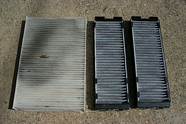
My filter had all sorts of black dirt, crud and leaf pieces in it!!! And I keep this car garaged, and never drive it in the rain (if I can help it).

The easiest way to get the new filters in is to put one in at the bottom, then once it is in, slide it up into the top position, since it is difficult to get the proper angle to put the top one in directly.

Here is the completed filter installation, with both filters securely in place. Replace the white filter cover, glove box, reconnect the light and air bag connectors, and this installation is complete. Ahhhh, fresh air to breathe once again.

Loading

Member Credit: TEQ-NIQ

Step 1: Remove shifter knob – Shifter knob is made of two parts, the leather handle, and the lower aluminum-looking cone-shaped piece. Grasp the cone-shaped lower piece, rotate counter-clockwise and pull down at the same time to release from shifter handle. Once this is done, there is a small gold clip holding the handle in place, remove this and handle will slide off, remove this as cone-shaped piece.

Click the image to open in full size.WARNING: 
If you twist the shift knob thing as instructed you will end up breaking it. You just need to pull down on that plastic piece. There is a TSB addressing this issue.

Step 2: Remove wood-colored faceplate and shifter piece – Open cup holder door. Using your fingers, press along edge of wood piece where cup holder door goes and pull up. Gentle but heavy force may be needed to pull up plate. Make sure you are slightly pushing the side of the plate inwards while you do this. Once you get the end of it released, you’ll need to put the key in the ignition, turn it till the air comes on, put foot on the brake and move shifter knob into the neutral position. Lift up the whole plate to completely release. Underneath there are two connectors, one brown and one white, that you will need to disconnect before removing plate. Set aside.

Click the image to open in full size. Click the image to open in full size.Click the image to open in full size.Click the image to open in full size.Step 3: remove two lower screws that hold the dash kit in place, place them in a safe place. Use fingers on inside of lower storage area (below cassette opening) to pull out the dash kit and release from its clips. Remove lower half first, then pull out upper half. there is another connector on the back of that piece that needs to be unplugged. Set dash kit aside.

Click the image to open in full size.Click the image to open in full size.Step 4: Remove 2 screws holding in climate/audio control panel and LED screen. Holding this panel from underneath the radio controls, Pull piece outwards. The two middle air vents are also attached, and will come out as well. Lift out lower end first, then tilt upwards to release clips holding in the top edge. One connector on the back needs to be removed.

Click the image to open in full size. Click the image to open in full size. Click the image to open in full size.Step 5: Remove LED screen: remove 4 small gold screws on both sides of LED screen housing to separate screen from the rest of the panel.

Now you have successfully removed the LED screen. Pretty easy! To put back in, screw 4 gold screws back in, put whole panel piece back in first by inserting clips on top edge back through their holes, then slowly lower front edge down while making sure top edge stays flush with rest of dash. Carefully reconnect the plug, then lower all the way back flush. Screw back in the 2 screws. take Dash kit, reconnect wires, pop in the top part first back into slots, then lower part, then screw in 2 screws at bottom. Put the car back in neutral, plug in 2 connectors to shifter panel (brown and white), then slip shifter tube through the hole on the shifter panel, and carefully fit the panel back into place, starting with the edge closest to the dash and ending with the edge closest to the armrest/cup holder. Place cone part of shifter back over steel tube, place shifter knob on and carefully slide the gold clip back through the white part of the shifter knob, it should line up with the 2 grooves on either side of the knob and the 2 grooves on steel tube. Slide cone-shaped part back up and carefully rotate over gold clip until its tight. It may take a couple tries to get this last part right.

Loading

Member Credit: prjctmax

So I purchased the “gusset,” aka the broken bracket and installed it today.

At first I thought I had to take the y-pipe off in order to do so…bad idea since I do not have air-tools and I got every single bolt off except for ONE! So I lay under my car thinking and starring at the damn bracket. And I figured out that I could squeeze my hands through there and take the thing out with a little effort and time, since the room is very minimal to work with.

Tools needed-14mm ratcheting wrench (makes it easier) and a 14mm socket with a short extension

After I got both of them off I compared and this is the “old” and the “new”

Click the image to open in full size.

Judging by the huge crack where the bolt goes in I figured that I should put a washer and “lock-washer” (or whatever they are called) in for added surface area so that after time the bolt would not “eat” through the bracket again and snap that piece off AGAIN.

Click the image to open in full size.

I also decided to keep the front heat-shield off that was needed to take out the front 3 bolts from the y-pipe.

Here is the final “product”

Click the image to open in full size.
[IMG]And the noise at around 2700-3000 RPM is now gone![/IMG]

Read more: http://my6thgen.org/f277/how-fix-metal-metal-sound-gussets-2727/#ixzz4VC072nfZ

Loading

Member Credit: bone-daddy

Ok so I have a Fujita CAI on my 04 SE, but my splash guard was broken a few winters ago, which a) I am too cheap to buy a new one, and b) makes getting at my air filter a LOT easier, but it also lets water in if I go through a car wash with and under body sprayer, so to remedy this, I built my own heat/water shield, and this is how I did it.

What you will need:
– Sheet metal or equivalent
–  Rivet gun and rivets
–  Drill bit sized for your rivets
– Something to cut the metal (snips, saw, cutting wheel)
– Vise
– Paint (optional)
– Grinder (optional)

I did the initial cutting before I figured I should take pics, but mainly this is how I did it.

Step 1:

First you must cut your main shield portion, I don’t have measurements but this is easily figured out by holding your filter next to the metal and seeing how tall you want your shield, once you cut it to that size, wrap it around your filter and see how far around you want it to go.

Step 2:

Now you need to cut the strips to rivet onto it, I would recommend starting with at least a 3 inch strip, mine were just shy of that and I wish I had made some longer ones, so I could put two rivets in each, but alas, I didn’t.

Step 3:

Once you have your strips, put them in a vice and then bend them into an sort of Z shape, with the end that attaches under the hose clamp only a slight bit larger than the width of the hose clamp, and if you can, put a slight bend on the very tip so it can’t slip out of the clamp. Test the fit by hooking the strips into the clamp while on the filter and hold the shield up before the next step.

Step 4:

Drill your holes and rivet the strips to the heat shield. Make sure the drill bit is the correct size for the rivets you have, if the drill bit came from a case where they slide into a metal index, you can test the rivet but sliding it in, you do not want any play for a secure fit.

You should now have something like this:

Click the image to open in full size.

Click the image to open in full size.

Click the image to open in full size.

Click the image to open in full size.

And if you please, you are done! However, I was not please, so I painted mine with truck bed liner. Also note I rounded off all edges with a bench grinder since I used 1/8 inch aluminum and a cutoff wheel on an angle grinder to cut my pieces, which left nasty edges.

Click the image to open in full size.

Total cost of this was $0.00, I used an old sign backing for the aluminum, borrowed the rivet gun/rivets, and had the bed liner in the shop.

Loading

Member Credit: Chernmax

OK, the Injen CAI mounting SUCKS, driving vibration first took out the rubber boot mounting screw, I reinforced the mounting and the freaken weld broke… DAMM… So some of you might have this (see pic below)

Click the image to open in full size.

My Fix, about $20 clams:

Parts Used:
1- ROL Exhaust heavy duty tail pipe hanger.

2- 2 RE Works High Grade Aluminum Quick Release Racing Clamps

The task: Using a vice, I bent the Exhaust bracket in a 90 degree angle and attached it to the lower engine mounting bolt just below the Injen, using 1 clamp, I added a new forward midbody support clamp by hooking it around the Exhaust Hanging bracket U-hook, (The Rubber vibration spacer allowed it to twist nicely into place and is 50 times stronger than the stock shock mount).

Another benefit; the bracket is now mounted under the CAI and eliminated all stress on the mounting hardware. I also replaced the rear bracket (not required, however stronger), tightened down all. Job time, 17 minutes…

Click the image to open in full size.

Click the image to open in full size.

Click the image to open in full size.

Loading