Okay guy here’s a little mod i had in my old Altima SE-R and am now bringing it to the Max family. I got all the LED’s from V-LEDS.COM ass well as the scotchlok’s for taping into the wires. Here is the mod, sorry for the crappy cell pic.
Materials/Tools
2 24in LED strips (front) your’e color choice
2 12in LED strips (back) your’e color choice
4 3m Scotchlok’s (they come in pairs so 8 total)
Wire cutters/pliers
Knive/cutting tool
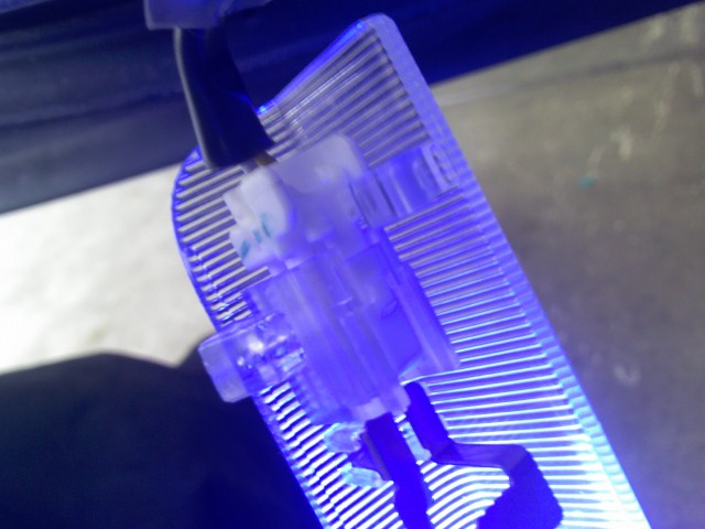
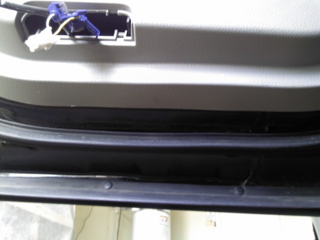
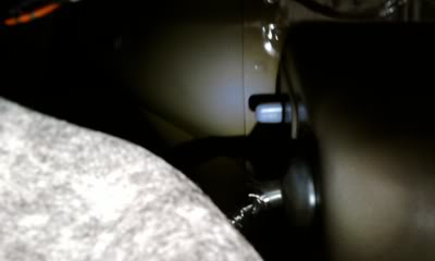
Step 1: So i started off with the rear ones where you will use the 12in strips. First pull out your’e step light like so.
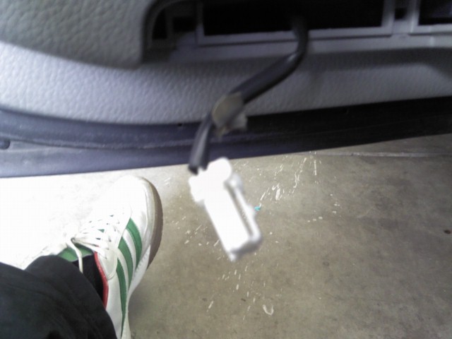
Step 2: Disconnect the step light from its plug.
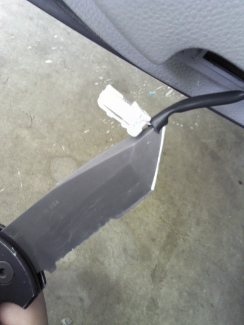
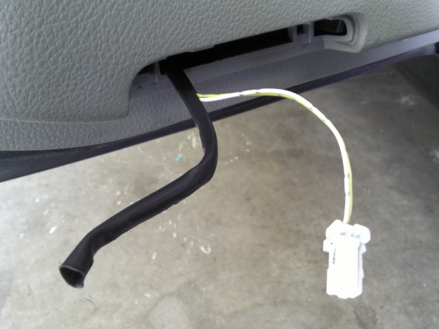
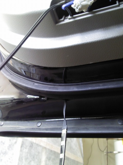
Step 3: So in all four doors the wires are under the black rubber covers. You will Have to cut them to expose the wires.
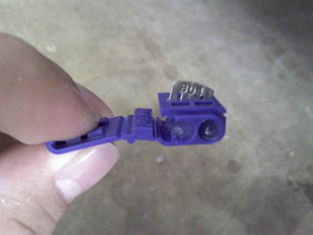
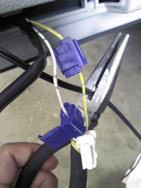
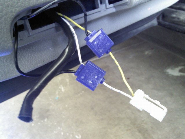
Step 4: Now you will start taping into the wires with the scothcloks. the open side is where you want to put the wires from the step lights, the open end where it only goes in half way is where you will put the strip wiring later. Theres also a video on v-leds site on how to use these.
Step 5: Press down on the metal piece in the middle to snug down the wire. DONT PRESS DOWN ALL THE WAY. You still need to put in the strip wire on the other side. all you want is for it to be snug so it wont move while you do the other wire.
Note: Sometimes the metal wont cut through the wire plastic so if you want you can pre cut into the wire to make it easier to splice.
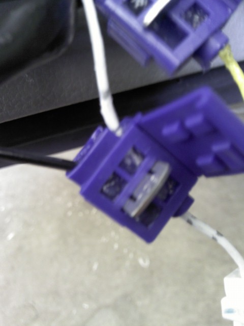
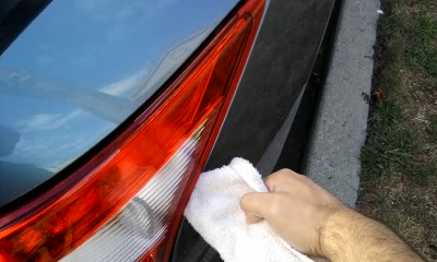
Step 6: Here is where you will put the strip, remember to clean it so you wont be sticking it to dirt. Also this is where you will feed the strip wiring from.
Step 7: Now give yourself enough slack on both ends but cut the strip wires to align to the step lights
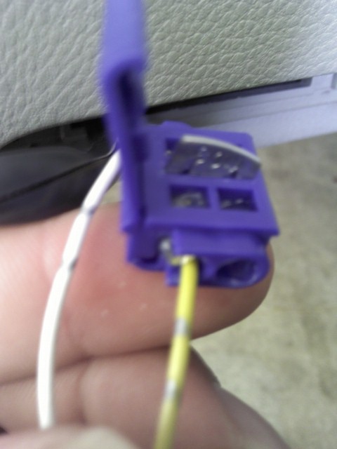
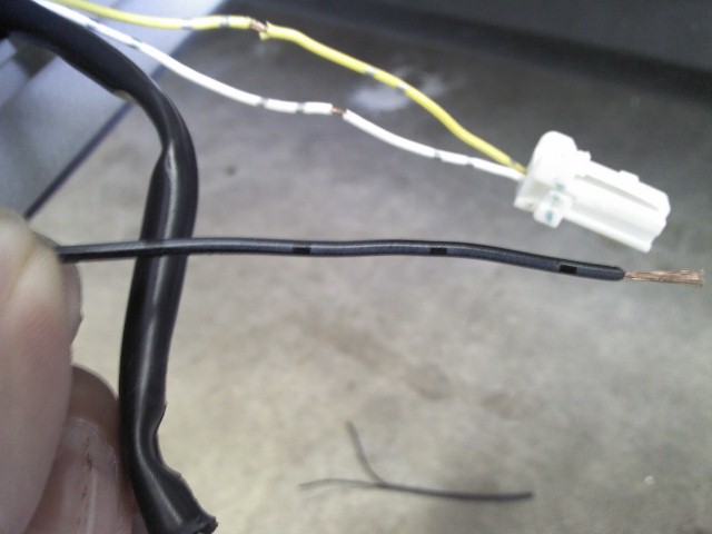
Step 8: The wire with the gray lines is the wire that goes to the yellow wire. The other wire with the small letters goes to the white wire.
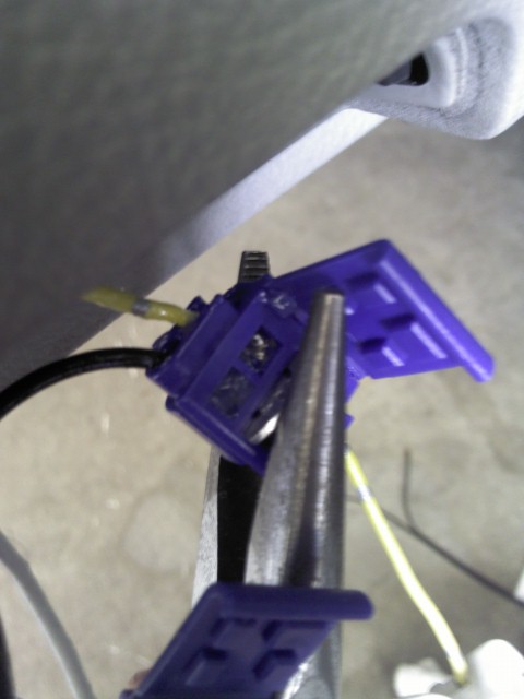
Step 9: Put the LED wires in there respective slots. Make sure you have some exposed wire before you crimp it down so that the little metal tab makes a complete circuit touching both wires.
Step 10: Before crimping down the metal tabs check to see if your’e LED lights up. If it does not MAKE SURE THE METAL TABS ARE TOUCHING EXPOSED WIRE ON ALL 4 ENDS. If it still did not light up make sure the wire with the gray tabs is with the yellow wire and the other with the white.
Step 11: Once they light up you may crimp the metal tab down. Make sure to do so tight so that the wires don’t come lose later on.
This is what you should have now with a lighted LED. You can cut of the black rubber, i did, or you can keep it, up to you.
Step 12: Stick the led to the bottom of the door now and again make sure you have a clean surface.
Step 13: Plug in you’re step light back up and place it back in its bracket, you should have enough room to fit it all back in there.
Step 14: Repeat for the other three doors.
Note: The front ones wiring was different. the LED wire with the gray tabs goes to the WHITE wire in both front doors, the other wire to the YELLOW.
Why? Beats me maybe the strips are different or maybe the car which i doubt. So again if it does not light up flip the wires and check.
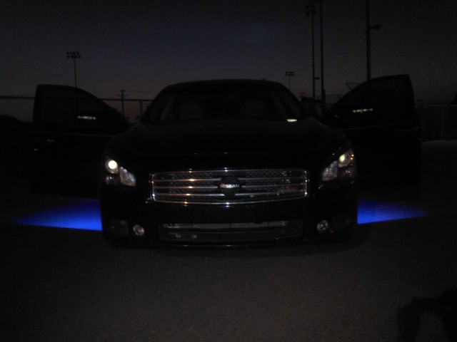
Step 15: Finish and admire you’re work with a cold beer.
Here are some more pics of the finished mod. Again sorry for the crappy cel pics.
Hope you guys enjoy the mod. If you have any questions please don’t hesitate to ask. For you that do the mod, please post up pics of you’re MAX here. It will be interesting to see how other people’s color combinations look like.
One word of caution to others: when I tried this method I broke a piece off my tail light. I noticed from comments on other forums a few others did as well. If you want a method of removing them without that risk you can get a rubber mallet and pound on the bolts that extend into the trunk until the tail lights pop out. I’ve taken them out several times this way now and it works great.
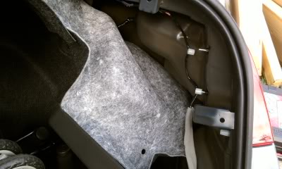
1. Remove the carpet lining. This involves removing several “push pin” things. It’s pretty straight forward if you look at it.
2. Remove the wire holder clips from the bolts:
3. Remove the 2 8mm nuts:
Once removed, shift the light out a little from that side
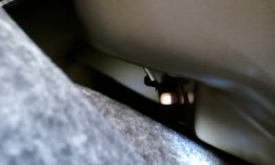
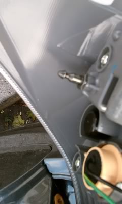
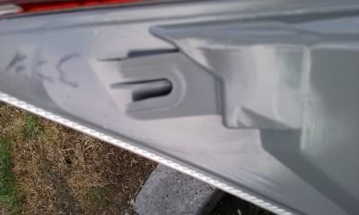
4. Carefully place a dulled (I have one that I rounded from the front for things like this) flat-head screwdriver in a towel or cloth. Wedge that near the clamping points on the light. There are two. The pictures below show the clamping pints from inside so you get an idea of where they are. There was enough space for me to get the screwdriver in and pull back while also pulling the light with my other hand. (Having someone to help pull the light is great too).
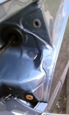
These are pins you are trying to loosen out
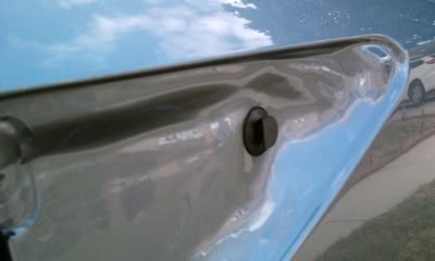
Here is where they go into the body
My passenger side light came off real easy but the driver side took some more effort. Don’t just wedge the screwdriver in one spot and pull. Keep creating a little space then wedge the screwdriver at a higher or lower spot and slowly loosen out the light.
5. Pull the light out and rest it in the empty space
6. Remove and replace the bulbs you want. (no pictures – very straightforward)
7. When replacing the light make sure to slide the guide at the corner of the light on the the pin. Here are pictures for clarification.
Additional Tips by: Nbpatel44
Make sure you remove the carpet floor and cardboard covering your spare tire. Fold any un-removable carpet into the front corner. Then, you have to remove the two big “push buttons” as I call them, for the entire rear plastic plate that hugs the back bumper on the inside. Then remove the three smaller push buttons along the edge of that same plastic piece. You’ll notice some bolts right here the trunk latch is, don’t touch those. Then to remove the actual plastic cover, you need to LIFT the pins out of their slots (there are four flat pints that point down into the ground). Then the cover should come off. I had to really rip this thing off by pulling towards myself. It seems the pins are slightly angled. You might need to pull hard to get the pins to release. You’ll see that these things aren’t really pins as they are like “stakes” that grab onto the metal frame.
For these push buttons that exist all over the carpet lining, they should involve taking a screw driver and prying up the “pin” and then the entire button afterwards. For installing, the pin cannot be pushed in when trying to push them. I used my thumb to create a small gap as I push the base of the button in. Re-installing is super easy, so shouldn’t have to force it too much.
After taking off the plastic cover hugging the rear bumper, start removing the push buttons around the edge of the carpet lining. I removed enough that I could really peel it back and gain access. There is a major plastic rivet I believe that points directly up on the trunk ceiling. That one was the hardest one to remove by far. It isn’t the same as the others, and mine was grey (if that makes a difference)
Then once you have access, pull off the plastic clips holding the wires to the bolts. Should be easy with a screw driver. On those same bolts, there should be a black nut with a wide flange, take those two off.
*Important part*
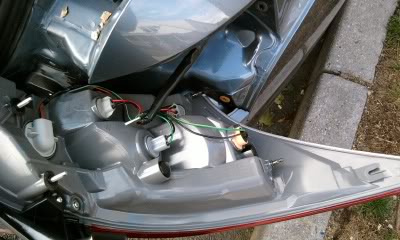
You need to unplug the wiring harness from the car. It is farther back towards the front of the car. Depress the “tongue” on the wire connector as best as you can with a screw driver as you pull (if you depress really hard it should be easy to remove – just wiggle). Sort of like an ethernet cable. The wiring connector that is not originating from the tail light should be fastened to the metal part of the car, so don’t rip that off.
Now that the wiring connection has been taken off, you’ll notice there is a rubber seal around where the wire enters the metal frame of the car from inside the tail light housing. You need to use a screw driver (or your hands) to push that rubber seal completely into the hole, making it disappear so the entire wire can be removed with the tail light. Otherwise, when you pull the tail light out, the rubber seal will stop the cable from exiting and pull on it unnecessarily.
Now you’re ready to pull the tail light out. The two bolts that are closest to the trunk opening (the ones you removed the nut and wiring clips from) can be hammered on (moderately hard) so the tail light starts to push out just slightly. I just placed a folded towel in front of the bolts and used a regular hammer. Without the towel might be okay, but it is super loud obviously. These two bolts are actually your tail light assembly so they need to be completely pushed out. I actually couldn’t hammer them out completely. I got about halfway.
Then I took a screw driver and wrapped a towel around the edge. It was a sharp screw driver so I didn’t press it too hard around the tip. Because the tail light was already slightly removed, I was able to go to the very front corner of the tail light and just lightly push it out and pull on the tail light assembly. It came out so easily. The trick to not cracking the light is not to pull with the screw driver until you’ve made progress with the hammer.
First thing I did was feed the wire from the new tail light into the car and pushed the rubber seal back through (you’ll know what I’m talking about once you see it).
Then I lined up the tail light with the two bolts, one corner slider slot, and two metal pins that are completely hidden the whole time until you remove the tail light.
I pushed in, it mounted well, I screwed the nuts back on, connected the wiring harness, did a quick lighting check to make sure I didn’t receive a faulty product. Then I peeled the carpet lining back, did the top ceiling rivet first, then the two buttons near the wheel well, then the rest near the trunk door. Then I popped on the plastic piece that covers the entire rear part of the car. Remember to line up the four flat pins that face down. Once they slide into the pin slot (you might need to pull towards you as you push down), then put the five push buttons back on (remember two of them are huge).
Done! Now that I know how to do it, it seems really easy to replace bulbs/entire tail light. I actually saved the wiring part of my old tail light (cracked) and will trash the housing.
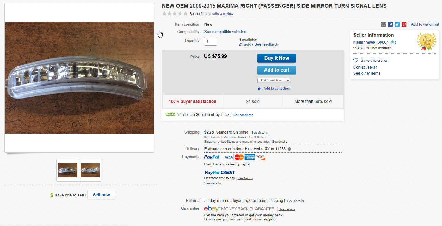
Just a quick how-to on replacing LED bars on side view mirrors. My car is a 7th gen 2014 Maxima. Some 7thgens don’t have the screw holding bar in. Just remove shell cover first to see if yours does. These LED bars are adopted from Altimas, so know if the listing for the parts says Altima.
You can buy the LEDs on eBay for around $75. Below are part numbers:
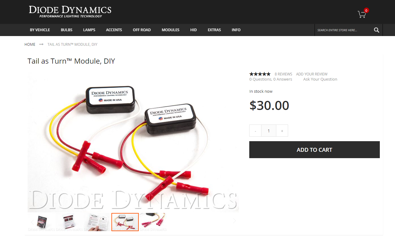
With this simple power control module, you can convert any LED tail lamp to also function as the turn signal, for a much more modern appearance. It will work very well in any vehicle where the turn signal is a traditional filament bulb. To install this module, you only need to work with the brake light wire and turn signal wire on each side of your vehicle. Installation is simple!
You can purchase the module from DiodeDynamics.com for around $30 bucks. You will also need to purchase a set of resistors to avoid hyper flash. You can purchase 6 OHM resistors for around $5-8 bucks per the set. Please also ensure to solder all connections.
When you remove your OEM radio, there are 4 plugs that plug into the radio. Only 2 of the 4 connectors are used with your new aftermarket radio which are the 2 connectors with the larger size pins. The other 2 are not used but the VSS wire is the brown wire located on the larger of the 2 connectors not being used.
Definition: Vehicle Speed Sensor (VSS) via Crutchfield
In addition to the standard power and ground leads, remote-mount navigation (and even some in-dash units) systems connect to a vehicle’s Vehicle Speed Sensor (VSS) wire. Your vehicle’s cruise control uses the VSS wire to determine the vehicle’s speed — it serves the same function for the navigation system. (Don’t substitute the tachometer signal wire for the VSS wire — the tach signal wire sends pulses as long as the engine is running, even when the car is sitting still.) The VSS wire sends a series of pulses (from 800 to just over 1,000 per mile) only when the vehicle is in motion. If the VSS wire is not hooked up, the navigation system will not realize that the car is moving at all, and will be unable to track position.
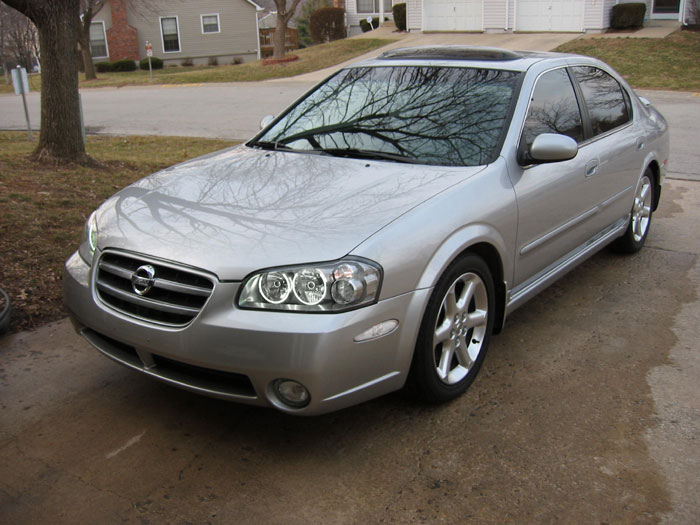
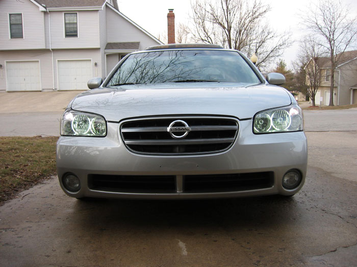
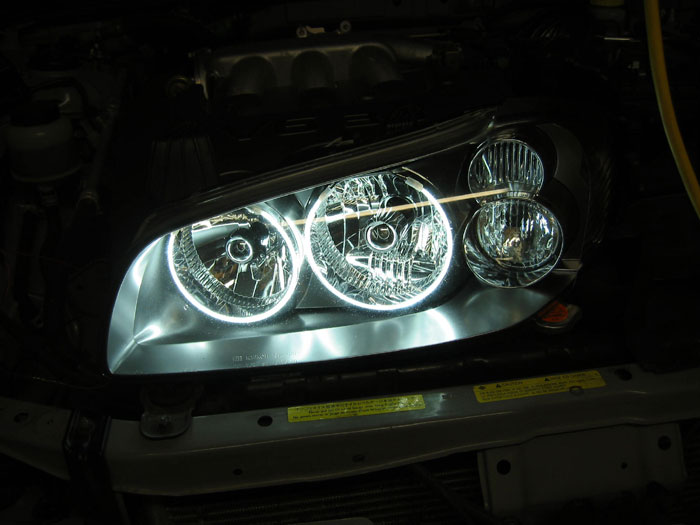
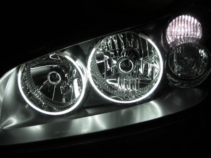
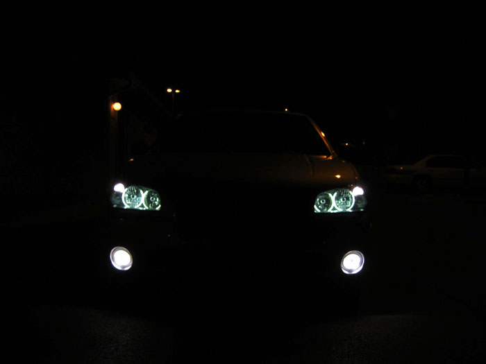
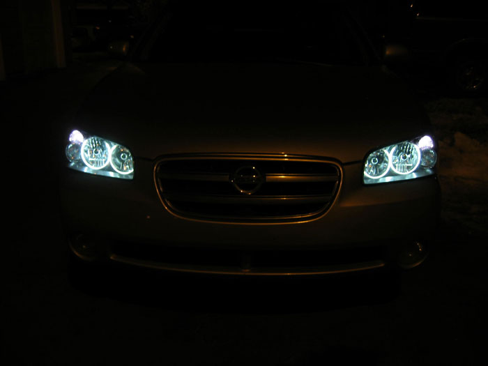
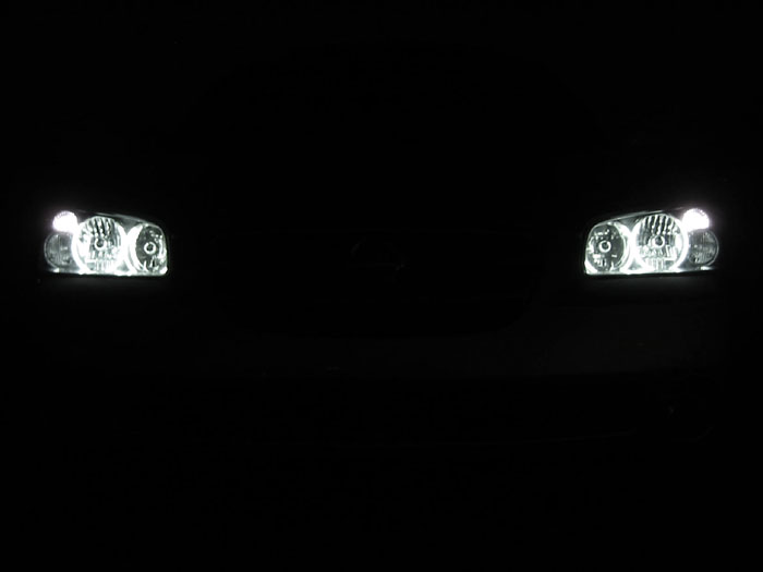
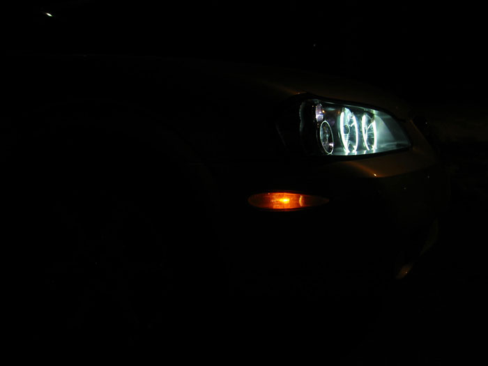
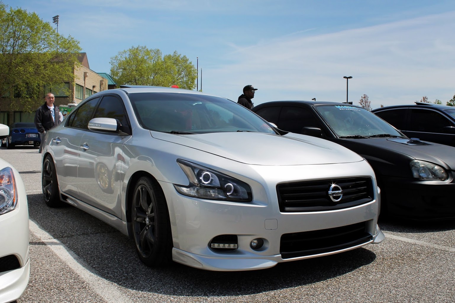
Pictures simply don’t do this lighting justice. Umnitza has a great product here that mimics the angel eye look found on select BMW’s, and in my opinion, clearly surpasses it. The DDE’s are ultra bright, very white, and an excellent compliment to the factory Maxima HIDs.
Umnitza provides a great how-to on CD-ROM when you purchase the DDE’s, but this how-to is helpful as a preview & supplement to the process. I performed this install multiple times and learned a few lessons along the way, so I’ve thrown in many of my own tips.
PLEASE NOTE: If you had the Nissan HID Anti-theft kit installed, the process for removing the headlights is much more involved and NOT outlined below. If your Max has the datadots install you likely have the HID anti-theft kit as well. DataDot stickers are placed on the front windows and possibly the headlights when the kit is installed. The additional bracketing itself isn’t easily visible so these stickers are the easiest indication. If you’re not in the NY area your car likely doesn’t have this kit. Sorry, to avoid abuse, I can’t provide any information on removing the kit.
Tools:
Oven
Cookie sheet
Small flathead screwdriver
Torx bit (on some models) – otherwise a 10mm socket
Socket Wrench
Old towels
90-second epoxy
Channel locks
Scissors
Toothpicks or Cotton swabs
Rubbing alcohol
Electrical tape
For optional hardwiring (highly recommended):
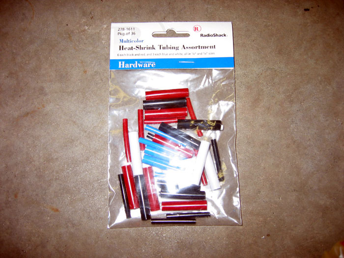
Heat-shrink tubing (optional) – Available @ Radioshack:
Heat gun, lighter or matches
Wire strippers
Soldering Iron
Solder
To wire the DDE’s as defeatable daytime running lights:
SPDT switch (single pole dual throw)
Around 25 feet of 22 gauge (or thicker) wire
Heat-shrink tubing – Available @ Radioshack
Heat gun, lighter, or matches
3 slide connectors
Drill
Drill bits
Wire strippers
Crimper (typically part of wire stripper)
Hanger
Electrical tape
INSTRUCTIONS:
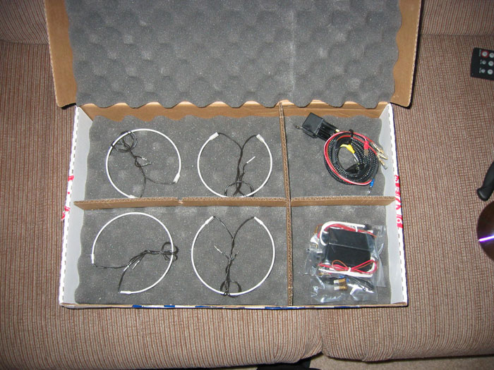
1. The kit:
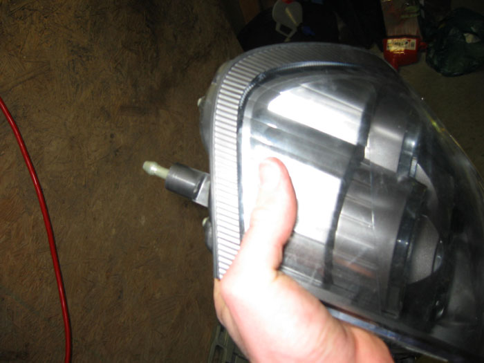
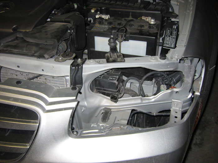
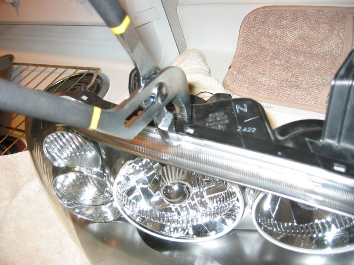
Test all of the rings in your kit. Take the ballast (the black rectangular box) and connect it’s wires to two of the rings. Then connect the red wire to the positive terminal on your battery and the brown wire to bare metal. The rings should light up. WARNING: When the ballast is connected to power, do NOT touch the brown and red wires together! This will blow your ballast. This warning is straight from Matt at Umnitza.2.Remove two bolts on top of the headlight (may be torx in some). Carefully pull headlight out. Pressure tabs will release. It takes surprising amount of pressure to pull the headlight out so don’t be afraid to pull. Take care not to scratch the fender with the metal mounting pin.
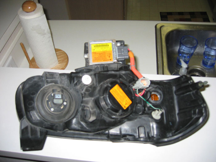
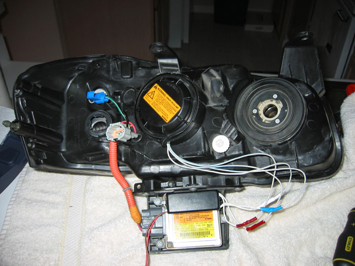
3. Remove the following from the headlight unit:
– All bulbs
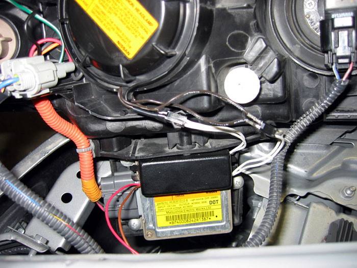
– The ballast. The ballast has the yellow and orange sticker in the picture below. It is attached with 3 screws.
– Three small screws that secure the clear housing on the front.
Everything else, including the remaining wiring, will be fine in the oven.
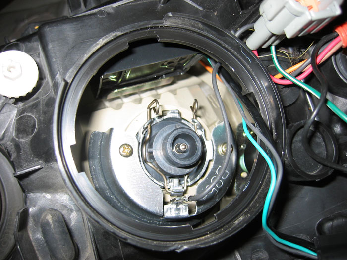
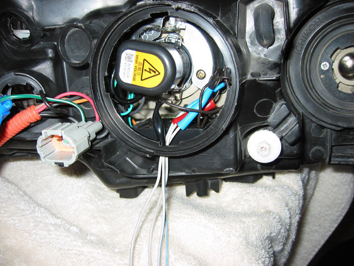
To remove the HID bulb, rotate the plastic cover counterclockwise. Then squeeze the 2 metal pins toward each other. Take care not to touch the bulb!
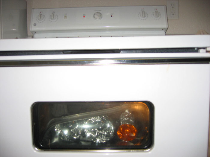
4. Wrap the headlight in an old towel and bake the headlight in oven on cookie sheet for 15-20 minutes at 200 – 250 degrees. The towel is a good idea to assure no part of the housing is directly touching the cookie sheet. Don’t let this part scare you. As long as you follow baking instructions you have nothing to worry about.
5 .Remove headlight from oven with old towels (will be very hot)
6. At this time you can also clear the blinker if you prefer
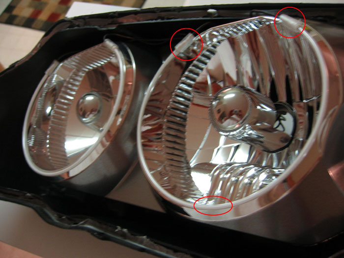
7. Use toothpicks or cotton swab to attach ring to the headlight with the small amounts of 90-second epoxy. Be careful – the rings are very fragile. Take care not to twist and bend them too much. The spots to epoxy are circled in red. After holding these points for around 2 minutes and the ring should be bonded like cement:
8. Route wires for the rings out the back of the headlight. Take care not to pull the wires
9. Reassemble headlight as best you can and return headlight to oven
10. Bake for 15-20 minutes at 200 – 250 degrees11.Remove from oven with old towels (careful – it will be very hot)12.Use channel locks to assure a tight seal. Go around the entire headlight squeezing it back together tightly while the housing is still hot. Take care not to scar the plastic – it’s easy to do when it’s hot. Using this process will assure a proper seal. No additional sealant is necessary since the factory sealant is reused.
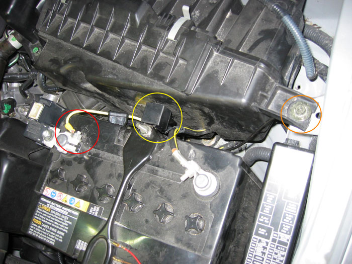
13. Connect power wire (with fuse removed) to positive terminal on battery (circled in red), ground wire securely to bare metal (circled in orange), and relay to battery tie down (circled in yellow). Be sure to scrape the paint off underneath the air box screw so the ground is attached to bare metal. Any spot where the ground can be attached to bare metal will do, so feel free to look around for alternative locations.
14. Decision time. Connect the red trigger wire to a switched power source. There are three options:
– Use the provided quick splice: Splice the red into the green wire with white stripe on the parking light or the red wire with the yellow stripe on the headlight connector. Wired this way, the DDE’s will come on when the parking lights or headlights are turned on.
– Wire the DDE’s to a switched 12V source. Wired this way, the DDE’s will be on whenever the car is on. Instructions here.
– Wire the DDE’s to a switch. This can allow you the best of both worlds: When the switch is “on” the DDE’s come on whenever the car is on. When the switch is “off”, the DDE’s come on whenever the parking lights or headlights are on. This is the setup I chose. Instructions here.
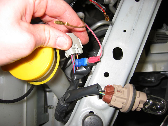
Quick Splice:
Spliced into red wire with yellow stripe on headlight clip:
15. Mount ballast for DDE’s near the headlights. One good option is the back of the headlight ballast. There aren’t many other good options since the wiring is so short. Be sure to clean area thoroughly with alcohol before attaching the ballast to assure a good bond.
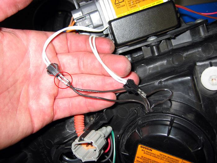
16. Time to connect the rings to the ballast. This means there’s another decision to make:
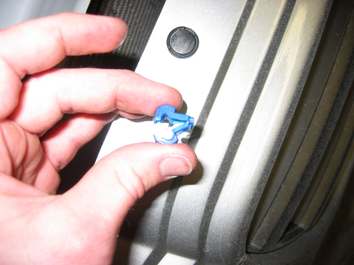
– Use the provided connectors. I (and others) had problems with the connections coming loose over time. Therefore, I don’t recommend using the provided connectors. If you choose this option, make sure the small points on the connectors are oriented on the same side as the points on top of the black connector. See pic for proper orientation:
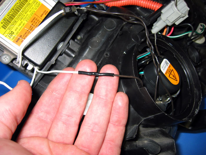
– Hard wire the rings to the ballast. Because I had problems with the connectors coming loose, I decided to hard wire the rings. This is pretty simple. Just cut the connectors off, slip heat shrink tubing over the wire, solder the wires together, slide heat shrink tubing over the connection, and shrink the tubing over the connection with a heat gun, lighter, or match. The result:
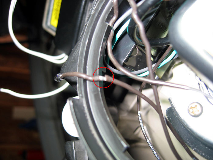
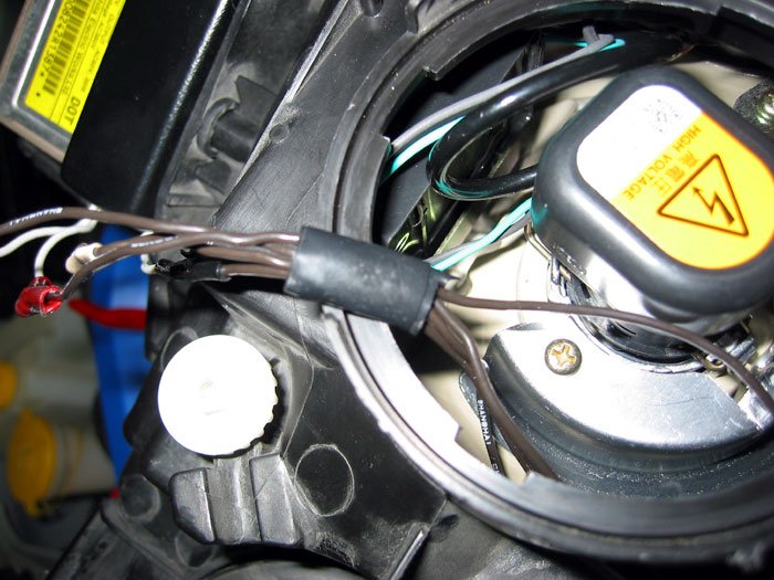
17.I also had a problem with the cap over the HID bulb rubbing through the insulation on one of my wires. To avoid this, I highly recommend either wrapping the wires in electrical tape to provide extra protection or drilling a hole under the dust cap and rerouting the wires the cap. I chose the latter. If you chose the electrical tape route, the cap will be hard to get back on with the electrical tape wrapped around the wires, but it can be done. Make sure the wires aren’t tugged on as the cap is tightened – try to hold them in the same place as you twist the cap.
The wire that was damaged by the cap rubbing through the insulation:
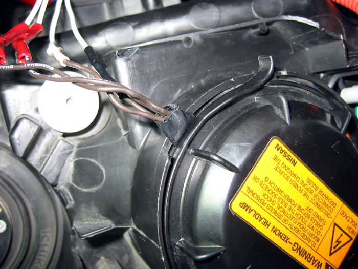
The added protection with the electrical tape:
The alternative method I highly recommend is rerouting the wires by drilling a hole under the dust cap:
18. Reinstall headlight. Make sure to repress the headlight firmly to assure all pressure tabs are connected.
19.Use the black ties (included) to secure the wiring as you route the wires through the engine compartment.
20.Insert fuse and leave the parking lights out overnight to allow the hot air in the lights to escape.


 Wire Located for Radio Installation?")