Member Credit: Matt Carey
This is a 5thgen Maxima with a 2009 R35 GTR steering wheel.

![]()


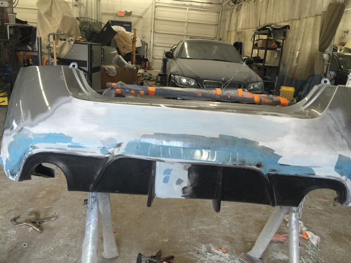
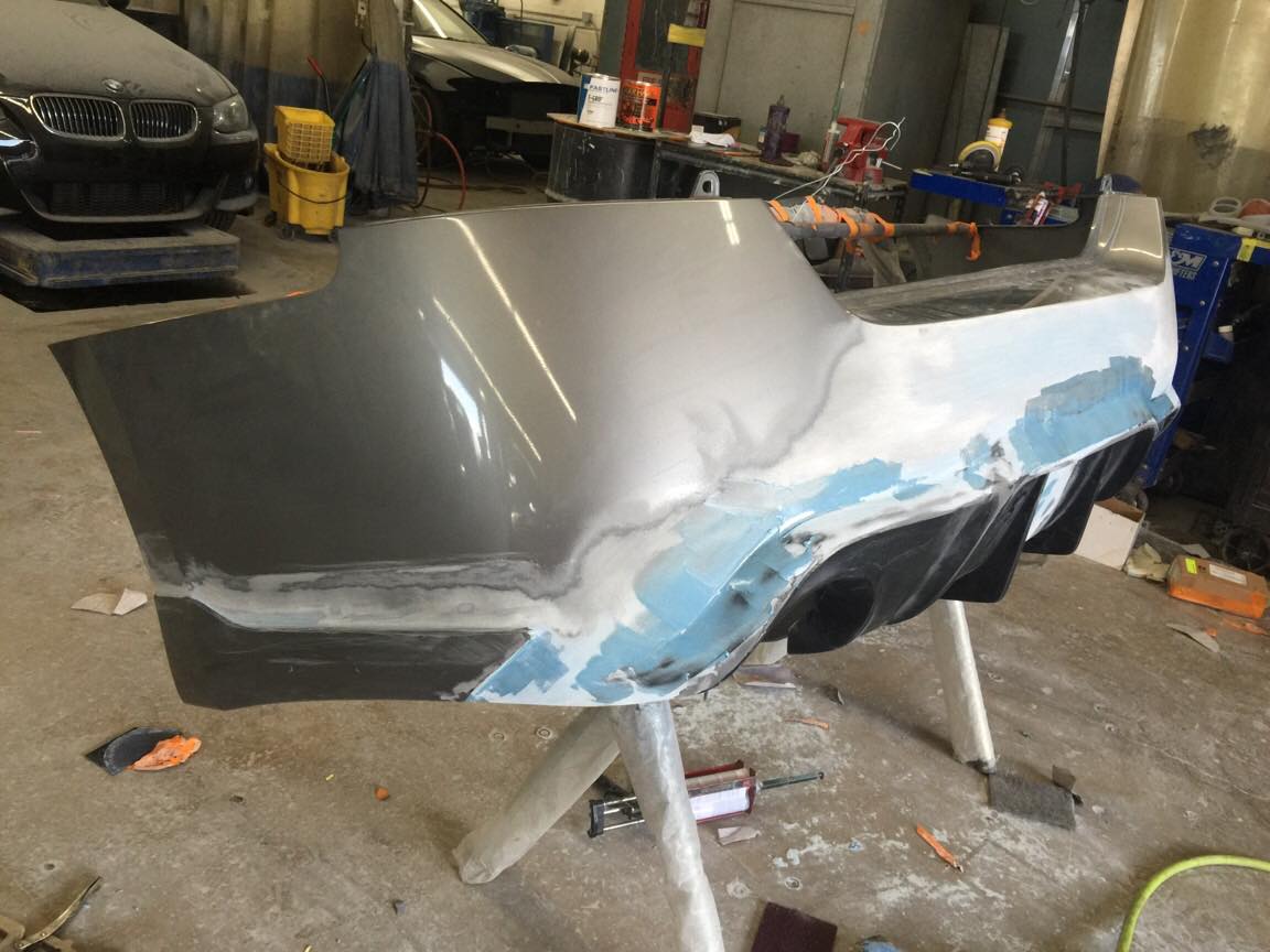
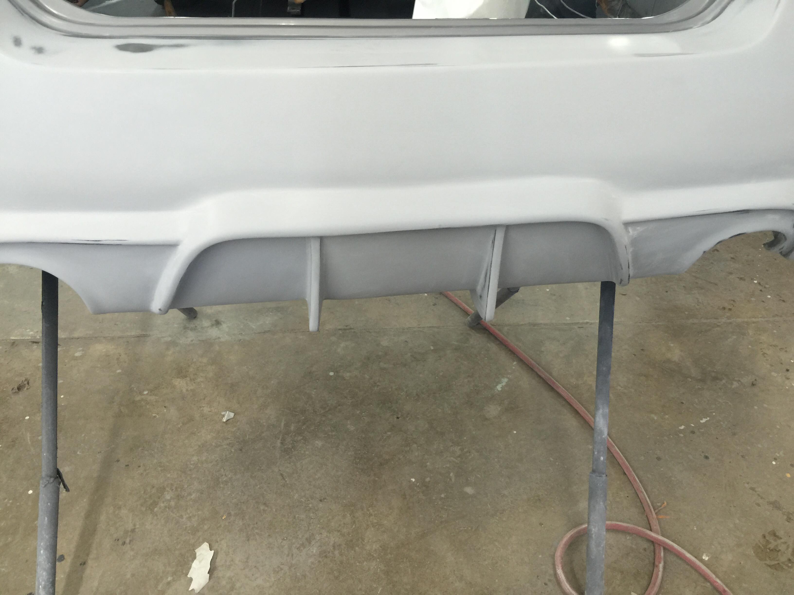
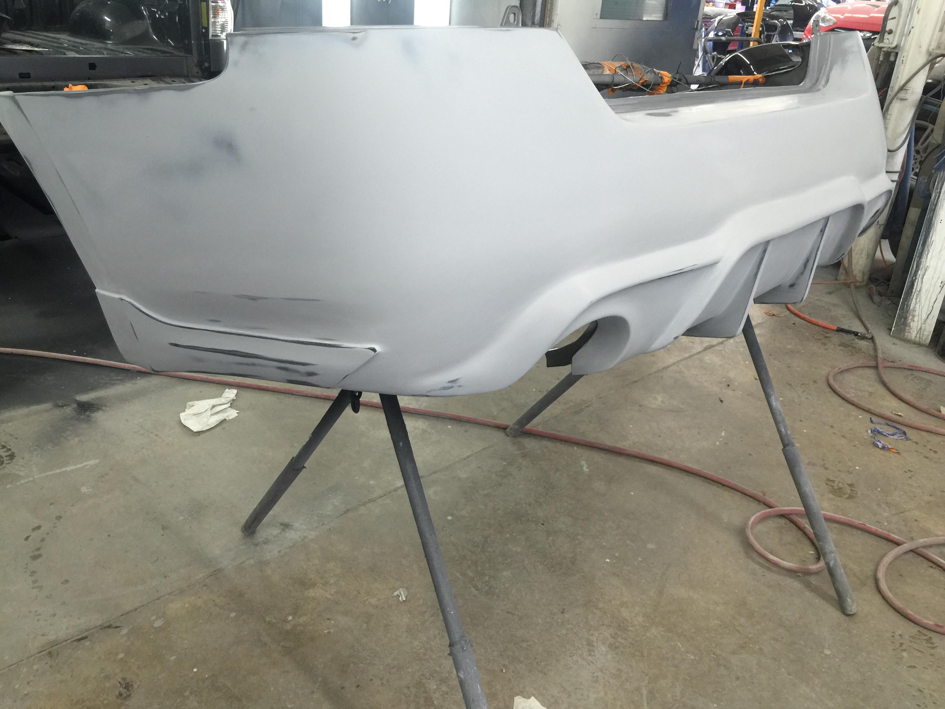
Member Credit: Shaun Guinn
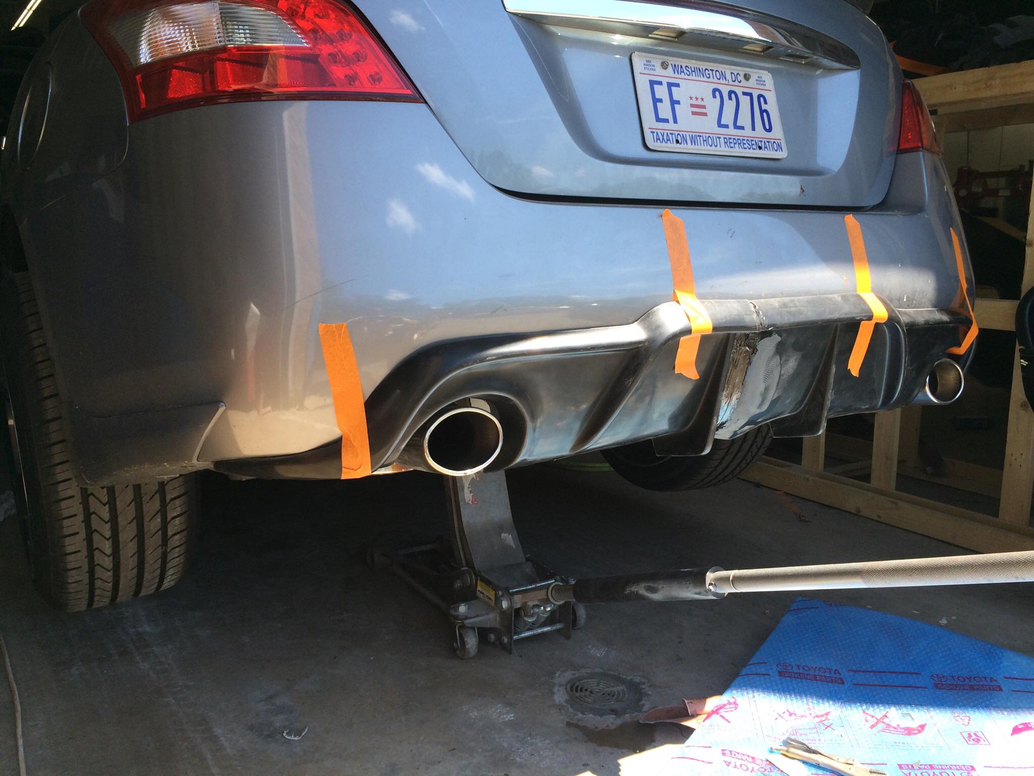
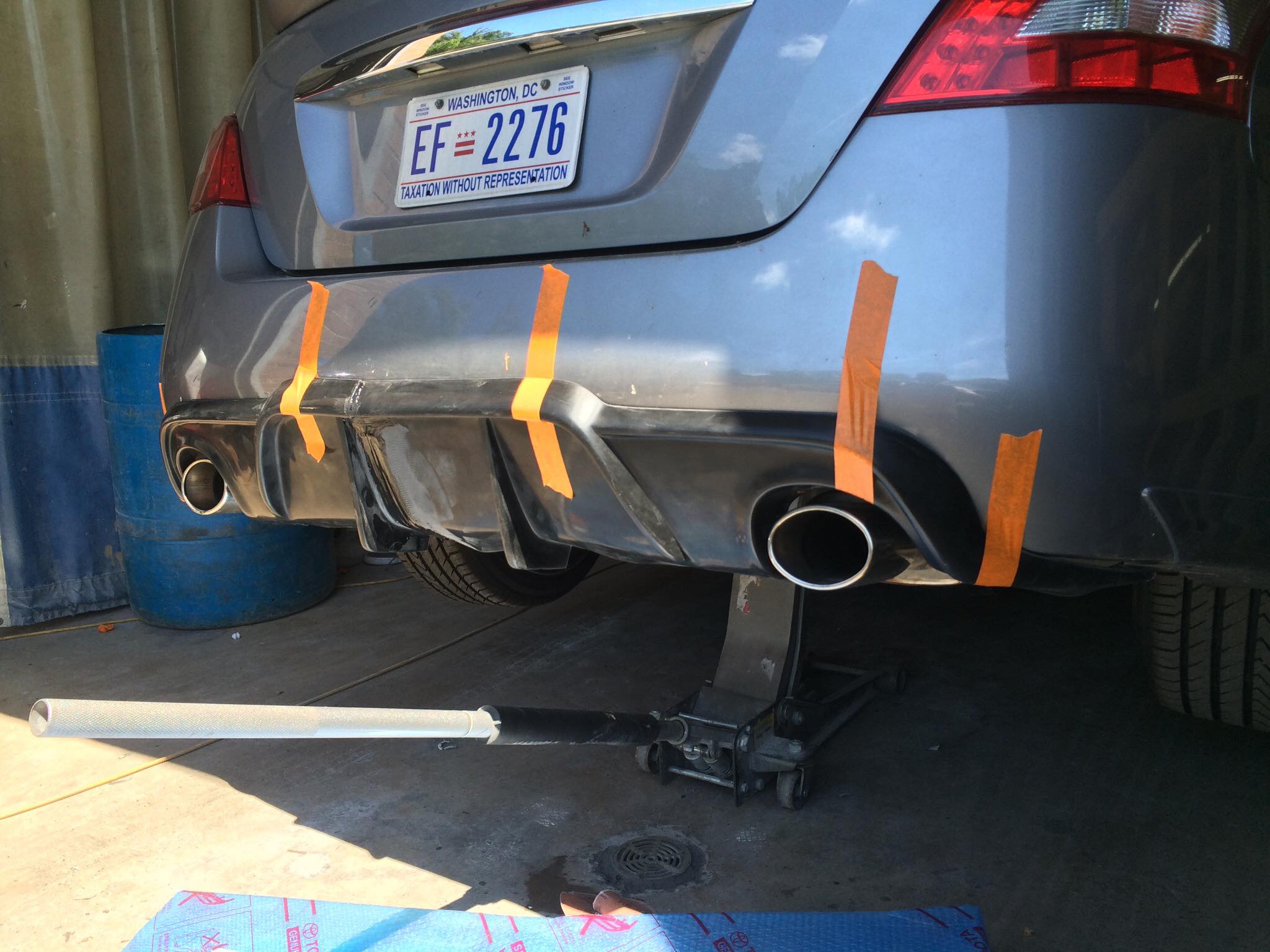
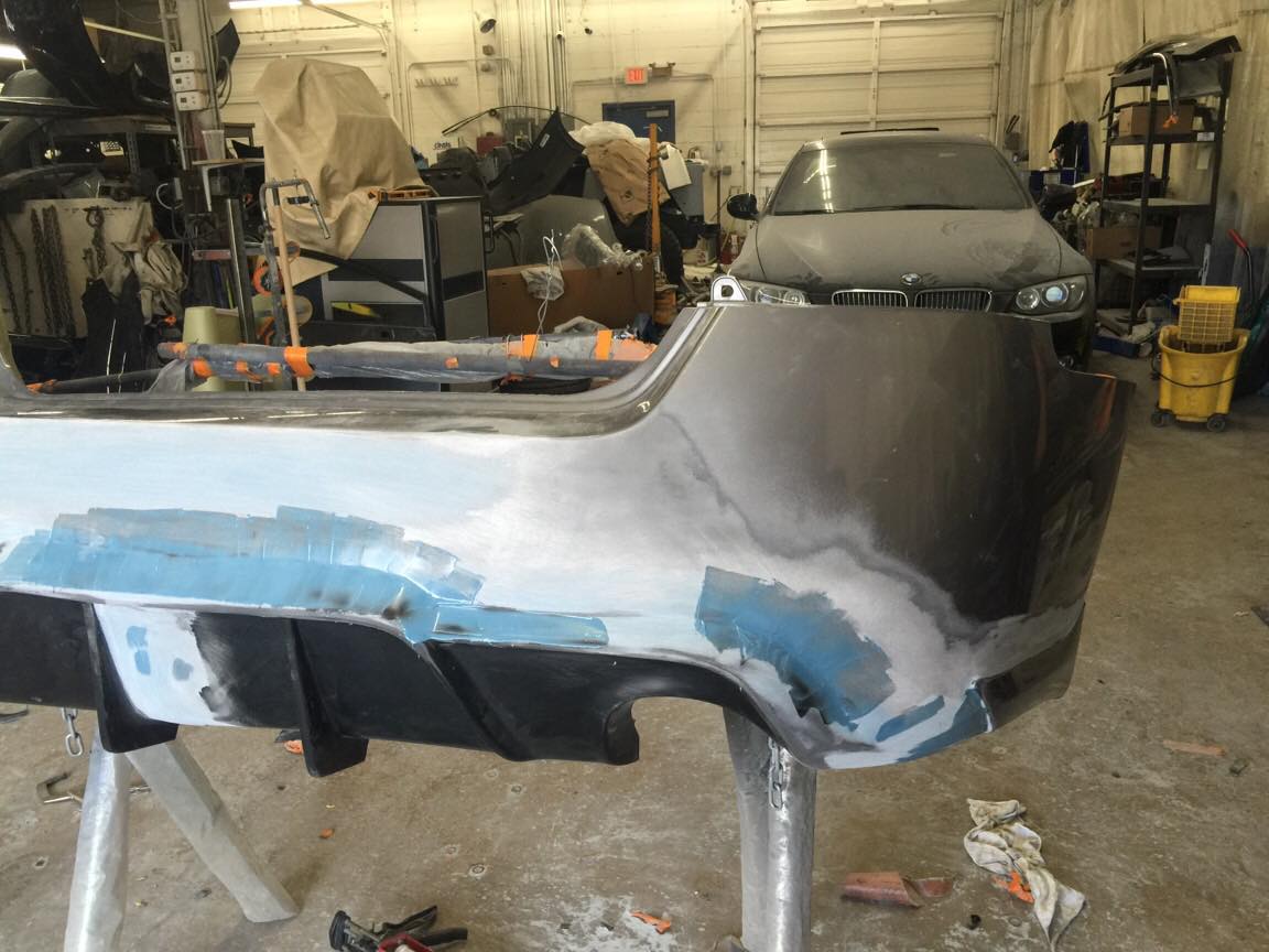
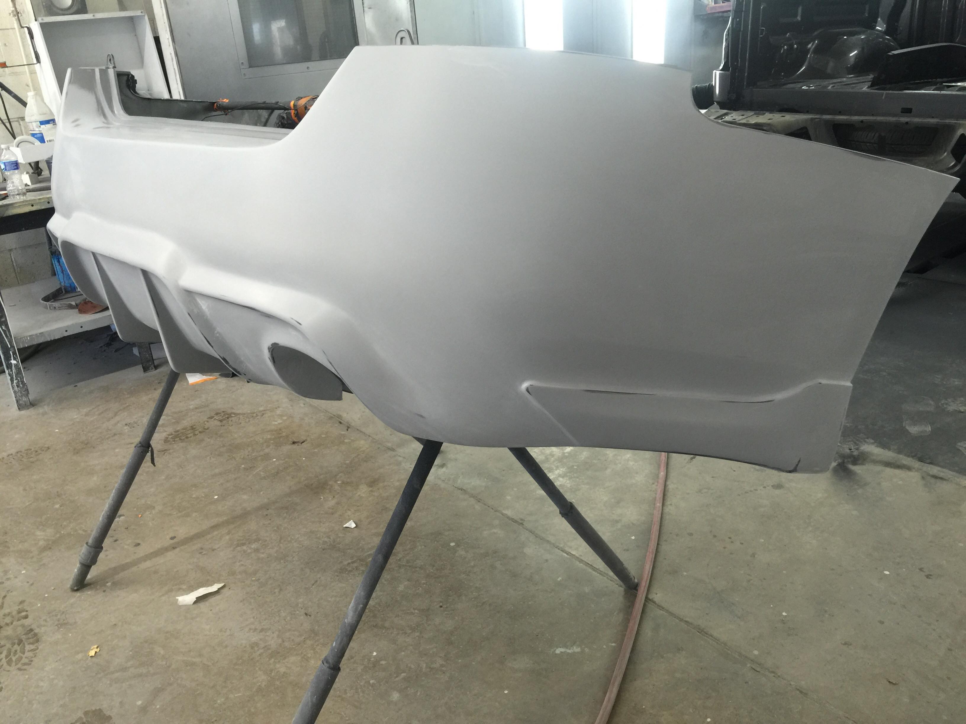
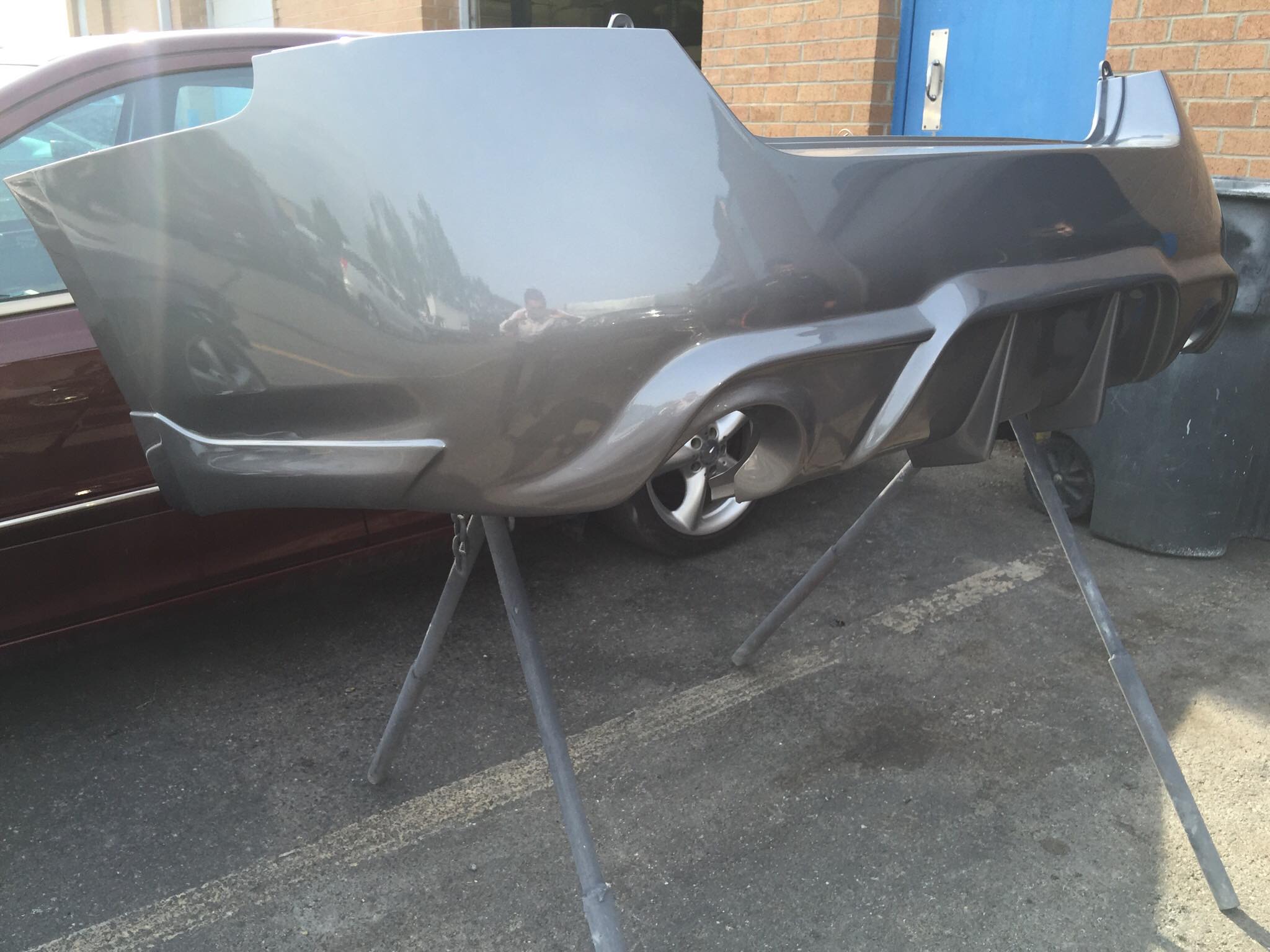
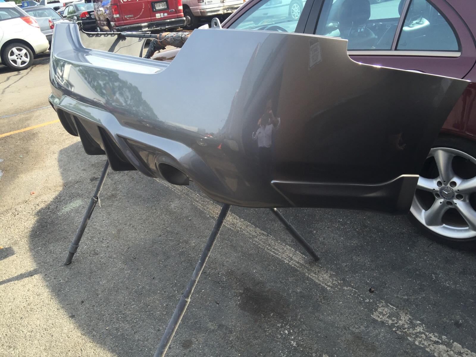
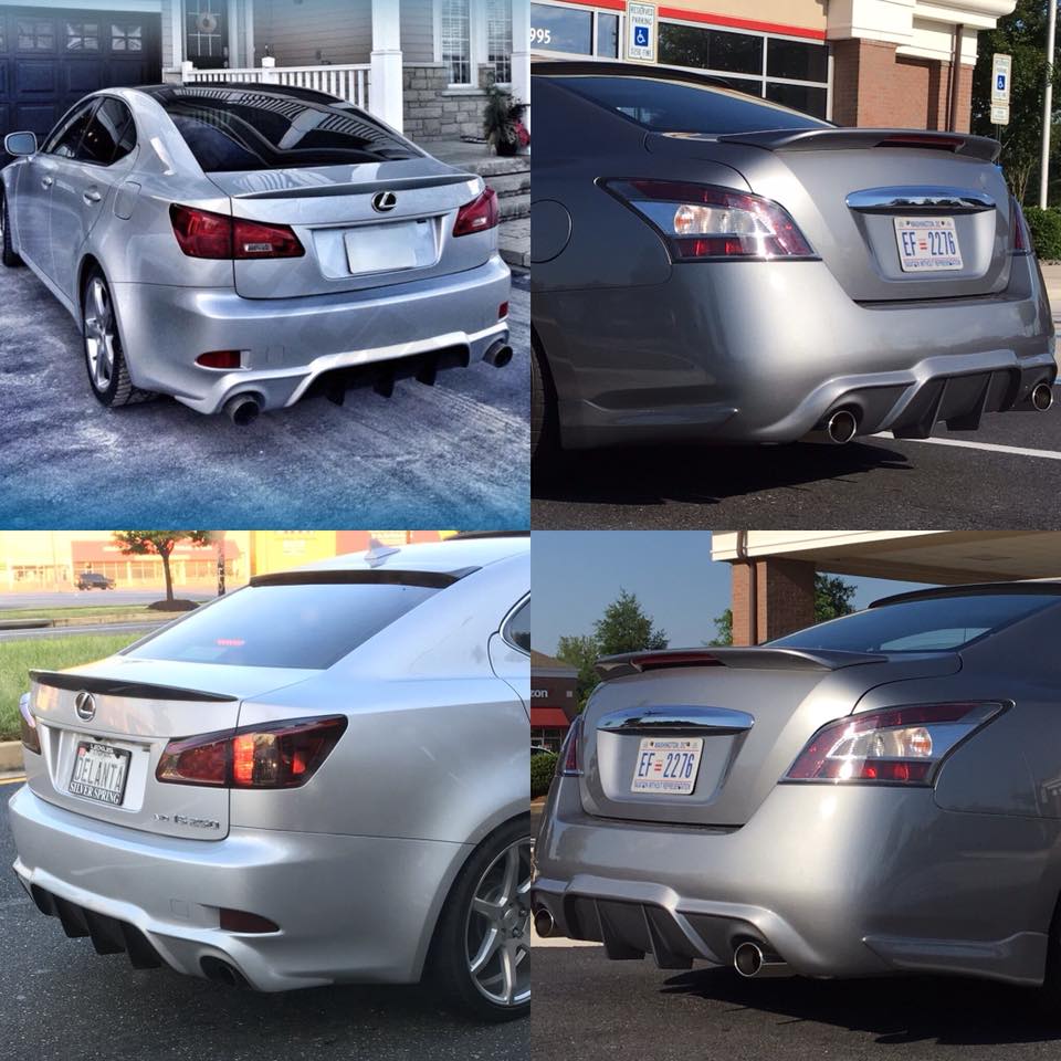
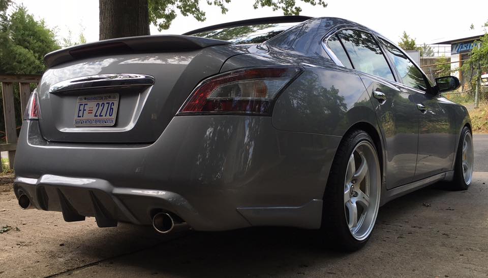
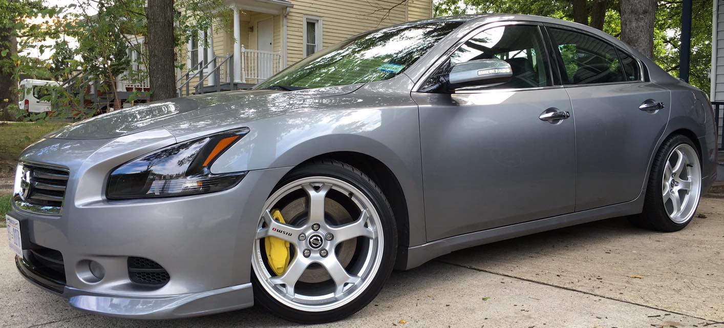
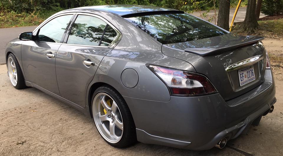
This is a 2006-2013 Lexus IS250 Type V Rear Diffuser installed on a 7thgen Nissan Maxima. It was custom molded onto the rear bumper. Looks awesome!


![]()

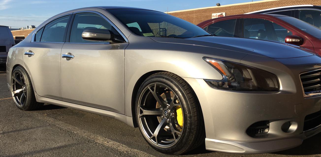
Member Credit: TunerMax
I am 98% sure of this set up for ALL years listed, there can be no confusion with my Guide, because it does NOT rely on color codes. The color codes change between years so DO NOT rely on them.
You want to hook up according to TERMINALS. The terminal designations are the same for 2000/2001, and for 2002/2003.
This set up WILL work on Canadian OR US models, DRL or not.
Just follow the terminal designations I’ve provided and you’ll be fine.
Here is the Complete hook up guide:
2000/2001 ————— Headlights —————- 2002/2003
 ————————-
Terminal 3 R——————————–Terminal 4 R (high beam)
Terminal 3 R——————————–Terminal 1 R (low /HID)
Terminal 1 R——————————–Terminal 5 R
Terminal 3 L——————————–Terminal 4 L
Terminal 3 L——————————–Terminal 1 L
Terminal 2 L——————————–Terminal 2 L (ground supply low beam)
Terminal 2 R——————————–Terminal 2 R (ground supply Low Beam)
Terminal 1 L——————————–Terminal 5 L
———————-Marker/Parking——————
 ——————————
Terminal 1 (coloured)———————-Terminal 3 (red/yellow[coloured]) Positive
Terminal 2 (black)————————-Terminal 2 (black/yellow[black]) Ground
————————–Signals————————-
 —————————–
Terminal 3 L (g/b [coloured] +)—————-Terminal 1 L (g/b [coloured] +)
Terminal 2 L (black -) ————————–Terminal 2 L (black -)
Terminal 3 R (g/y [coloured] +)—————-Terminal 1 R (g/y [coloured] +
Terminal 2 R (black -) ————————–Terminal 2 R (black -)
These are the relevant power-flow wiring diagrams, for clarification of the above Guide, should you need it:
2000 headlights DRL CANADA:

2000 Headlights USA:

2000 Parking Lamp in Headlight:

2000 Signals in headlamp (same E24/E45 harness as parking):

2003 Headlights DRL Canada:

2003 Headlights USA:

2003 Parking lights in Headlight (same E161/E165 connector as Headlights):

2003 Signal in headlight (different harness from parking lights):

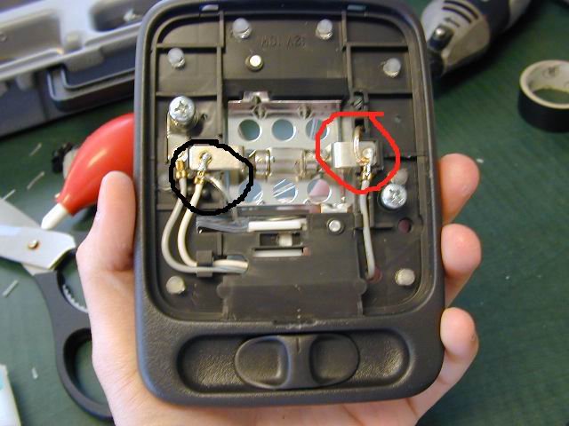
Here is a pic to show you guys what harnesses you need. This is a temporary post until I complete the DIY portion.

The harnesses circled in RED are NOT necessary, they plug into the ballasts, and SHOULD be included with your headlights. If you bought aftermarket headlights with OEM ballasts, you will need them. If you bought aftermarket headlights with aftermarket ballasts, you’ll need just the marker light harness (generic, but OEM is recommended).
Note, you WILL NEED bulbs of course, but they are NOT part of the harness, you can purchase them separately (for the noobs that aren’t sure), marker light type is 168.
This is what you need for harnesses:
2 – HID harnesses
2 – High Beam Harnesses (Bulb type is 9005)
2 – Signal Harnesses (Bulb type is 7440)
![]()

Member Credit: DeusExMaxima
I looked at and sat in many many seats. I had several criteria:
1. Lightweight (under 35 lbs) – This is an easy way to drop lots of weight. The OEM seats are 65 lbs EACH.
2. High bolsters – I want to be held in by the seat. I like high side bolsters
3. Charcoal leather – To match my interior. I would have bought cloth seats, but I would have had to re=cover them in leather later.
4. Reclinable – This is my daily driver, with different people driving. I really wanted reclinable.
I chose leather seats from aa Mitsubishi Lancer Evolution 8. In this pic the OEM passenger seat is still in, but the drivers seat is the Recaro

This was a rare option on these cars. I remember sitting in an Evo with leather a few years ago and LOVED the seats. They are aggressive, but not so much so, like Brides. They arent to hard to get in and out of. In fact, the lower bolster is similar to the OEM Maxima seat. The top part is much more aggressive, like sitting in a cradle. It is much firmer than the Maxima seat, yet it forms to the body. They are incredibly comfortable.
I had Wedge Engineering fabricate a beautiful bracket and slider that fits perfectly. They used a jig from the Bride seats that Sexima (org member) had in his car.
Installation:
1. Remove the plastic covers and the 4 bolts holding the seats in.
2. Disconnect battery, and wait several minutes.
3. Tilt seat back and remove the connectors for air bag and other electronics.
4. Carefully pull the heavy seat out of the car.
5. Install the 2 ohm 1/2 watt resistor in the air bag connector.
6. Install the new seat, and bolt it down. Now is the time to install harness too if u have one.
Comparison of Maxima seat and Recaro seat:

Top view of Maxima seat and Recaro seat. Note the much deeper bolsters in the Recaro:

7. Remove seat belt receptor from OEM seat and install on Recaro bracket:

8. Seat installed with Sparco harness:
The seats look a bit stained but its cuz I used tons of leather conditioner. They look stock but slightly aggressive, and the leather matches PERFECTLY. I am extremely pleased with these seats.
Here is a day time pic:

![]()


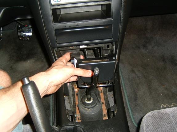
Member Credit: Tavarish
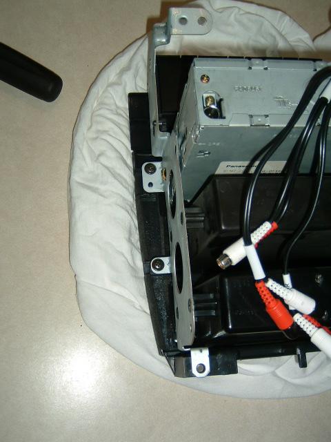
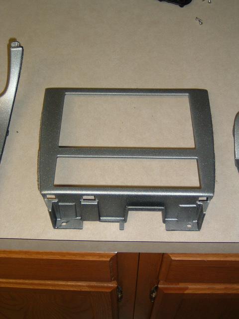
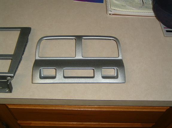
*VERY IMPORTANT** Make sure you have the wiring harness, or else this will be impossible.


Then I test fit it with the stock mounts. Don’t try this. It will NOT fit at all. What I did was take off the stock 5th gen mounts with pliers (they snap right off), and sawed the top one off. (I didn’t use it.)
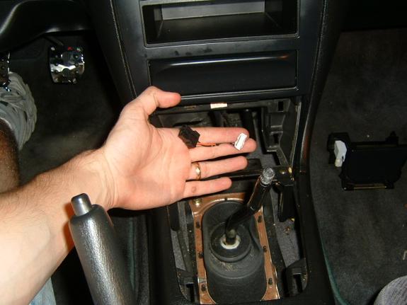
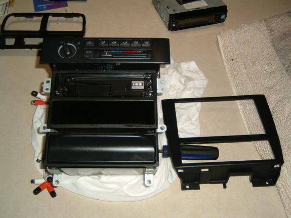
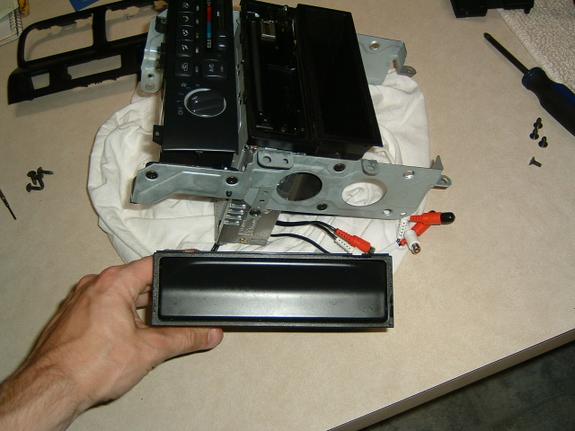
What I did is i got a spare bezel I had laying around, and put the lower mounting holes on from that. I attached them with JB weld.


Then I mounted it. PERFECT fit. Not 100% OEM, but no one will be able to tell.
Now here comes the fun part: wiring. I made a custom wiring diagram by looking at both FSM’s, and playing connect the dots. It was pretty easy, you just have to double check each wire is the correct one you’re splicing.

It was about 29 wires altogether, I got rid of wires like ABS and Cruise, since I no longer have/need that in my car. I don’t have TCS, so that went as well.
Always test it after the first few wires to see you’re on the right track. I did the power wires then the illumination wires to see if it lit up and turned on.

Then just finish up the wiring, bolt it down, and hopefully everything comes together.
Here’s the finished product:


![]()

Member Credit: Max2damax
Basically what is going on is that the connector on the oem bulb is thicker that the connector the led tail lights, so all you have to do (make sure the car is off and you don’t have the any lights on) is close the pins on the stock connector and spread apart the pins on the lights, look at the pics.
And once again, make sure you have the black cable line up with the white black cable on the car!!!
BEFORE
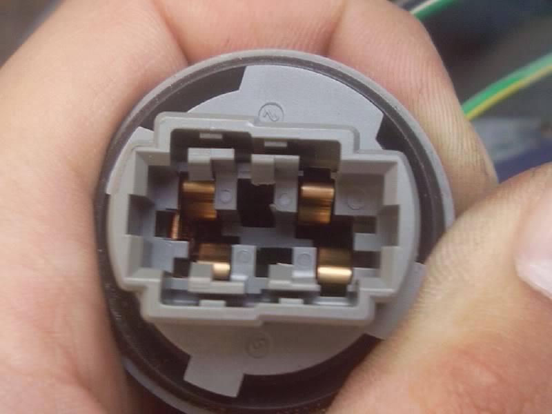 AFTER (MAKE SURE THE LEADS DON’T STAY TOUCHING EACH OTHER AFTER YOU OPEN THEM)

Additional Pics Courtesy of Gollum67


![]()

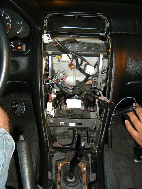
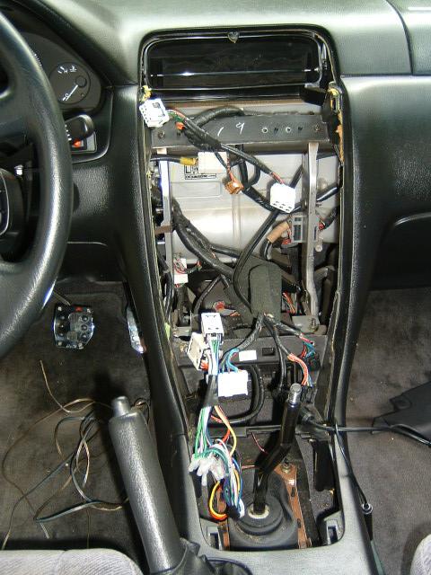
Member Credit: Cheston
WARNING: These are JUST directions. I am NOT liable if you mess up your car. Use common sense when attempting this or ANY mod. Always use caution when it comes tools that use electricity. WEAR PROTECTIVE CLOTHING!
Tools needed: phillips & flat head screwdriver, 10mm socket, 12mm socket, 6″ extension, THIN needle nose plyers, pencil
1 Set the height of the steering column to the lowest it can go.
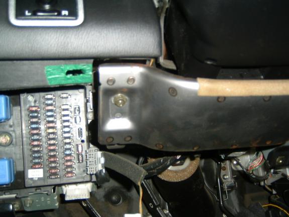
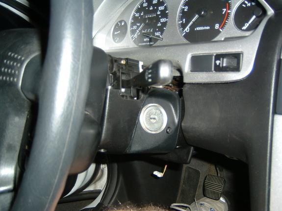
2 Remove the plastic bottom cover to the steering column, it’s the piece that’s above your knee. There are two screws near the bottom, and then pull out.
3 Remove the Metal shield covering the bottom of the steering column. Two 10 mm bolts here.
4 Remove the bolts holding the steering column up, two 12mm bolts. Use the extension if you have trouble reaching up in there. Drop the steering column down.
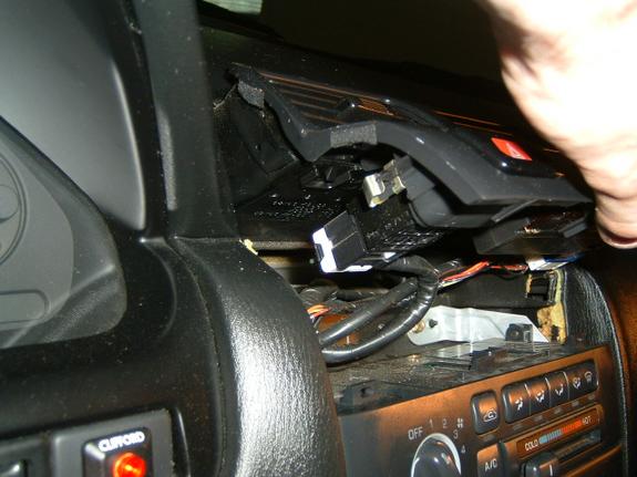
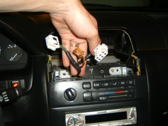
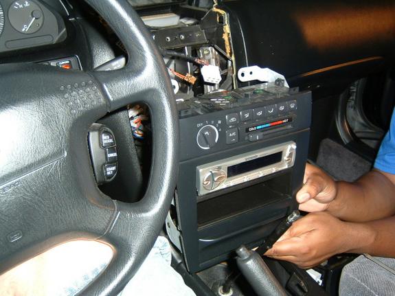
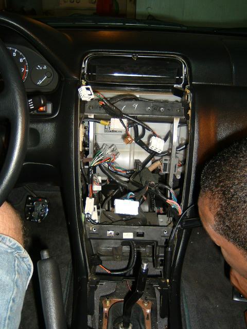
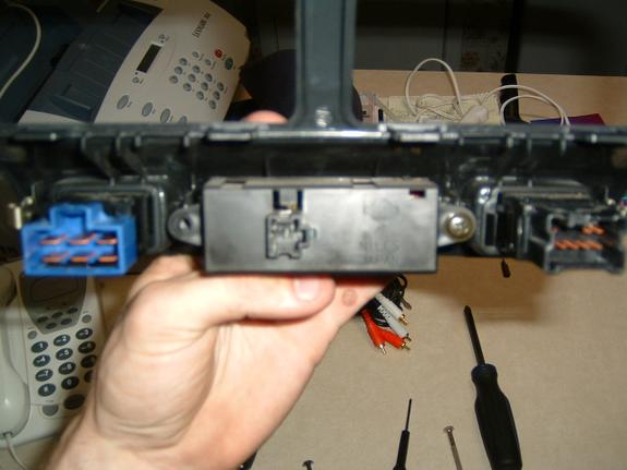
5 Unscrew 2 screws holding in the top of the dash, it’s the plastic cover underneath that overhang. Pop down the top half way. Using some firm BUT consistent pressure, pull back on it, removing the cover from the dash. There are four little clipies that are holding it in, so besure to find those clips. Unhook the cables that are attached to the cruise control and dimmer switches.
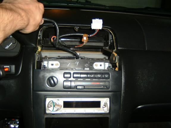
6 Remove the three screws holding in the dash cluster. Unhook the four clips in the back and then take out the whole cluster. Now, unclip the plastic over and the black casing.
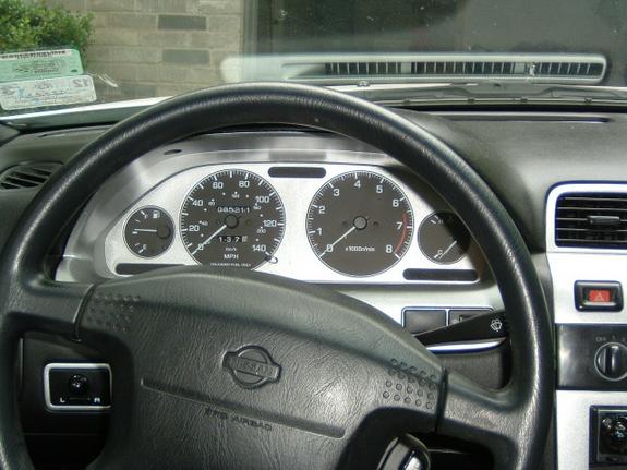
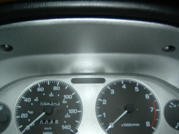
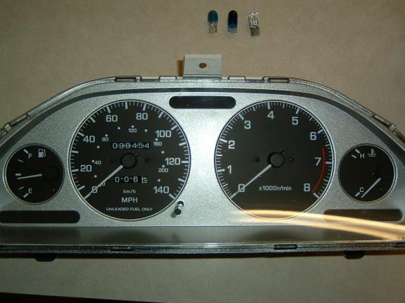
7 Now take the dash cluster to a place where is WELL LIT, and comfortable. You’re about to do something delicate. Note the FUEL level.
8 To remove the needles, you fist need to take off the needle-rest stops. Those are the little black thingies that the need rests on when the car is off. To do this, you need to lift up the gauge pieces ever so slightly to get the tweezers in there to pop off the plastic rests. after you have take out all three, rejoice. and take a breather.
9 Now, starting with the speedo, gently push the needle COUNTER CLOCKWISE until you feel a little resistance. MARK THIS SPOT WITH A PENCIL. this is your recalibration POINT. you’ll need to return the needle to this EXACT spot when you put back on the needle or else your speed readings will be seriously fucked.
Mark down the recalibration point for the tach too.
Mark down the recalibration point for the temp too.
10 Now, starting with the speedo gauge. gently, turn the needle COUNTERCLOCK wise three times. The pressure should get lighter and lighter the more turns you do. After the third turn, turn and LIFT up the needle. YOU MUST GENTLY LIFT WHILE TURNING or else you’re toast.
Turn about 3-4 more times while lifting and the needle will pop off the small metal shaft. If you pull out the shaft, you’re what we call in Chinese: a Man-toh. A Dumpling. A Dense white piece of toast, lamer than day-old bagels.
After you get the speedo needle off, do the same with the tachometer, remembering to LIFT while turning. And then repeat for the fuel and temp
11 Now, that you have all the needles off, do what you want to the gauges. Either swap out new ones or paint the stock ones. You can do what i did, and get overlays to change the stock ones into some cool colors.
12 Once you’re done with that you’re doing, then place the gauge back on, and position the needles at the 4 oclock position.
Gently press down. When it’s pretty much in, gently turn the needle, while pressing down, until you turn it to the recalibration point that you previously noted. If you over shoot, that’s ok, just go around again CCW.
RECLIP in the needle-rest stops.
13 For the FUEL and TEMP needles. it’s going to be tricky. My suggestion is, plug in the cluster, and then turn on the car. Since you noted the fuel level when you first started the car, move the needle to that position. And after three minutes, the temp needle should be dead center, that’s the “normal” temp reading, so move the needle to the middle.
14 Reclip the black casing, Reclip the plastic shield. Reattach the wires to the back of the gauge cluster and screw in those three screws.
15 Re-attach the dash cover, remembering to replug the connections for the cruise control and dimmer.
16 Re-attach the steering column. Re-attach the steering column metal shield.
17 Reclip the dash bottom covers, remembering to screw those two screws in.
18 Turn on the car. Rev it up. Does the RPM needle move? Does the Fuel register? Go fill up and see where exactly “F” is. Is the temp right? Is the Speed right?
19 Good. You’re done.
![]()

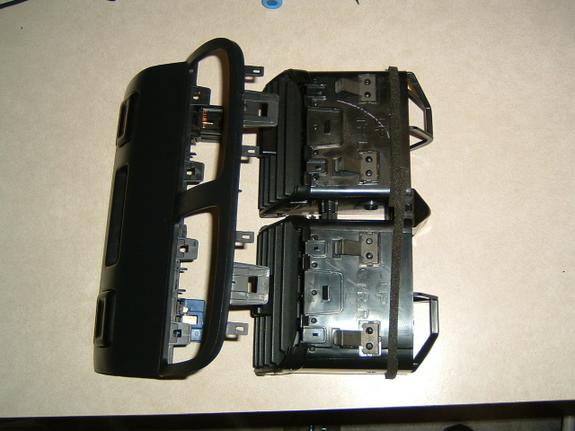
Member Credit: d_warner
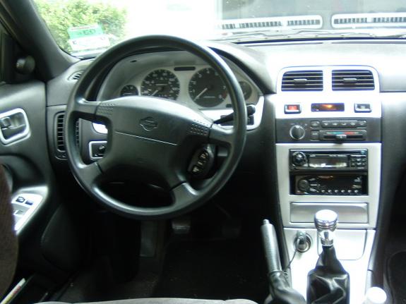
OK. I’ve had some people ask me about the painted dash in my 97 GXE. For those of you who really want to know, here’s a short and I mean short write up.
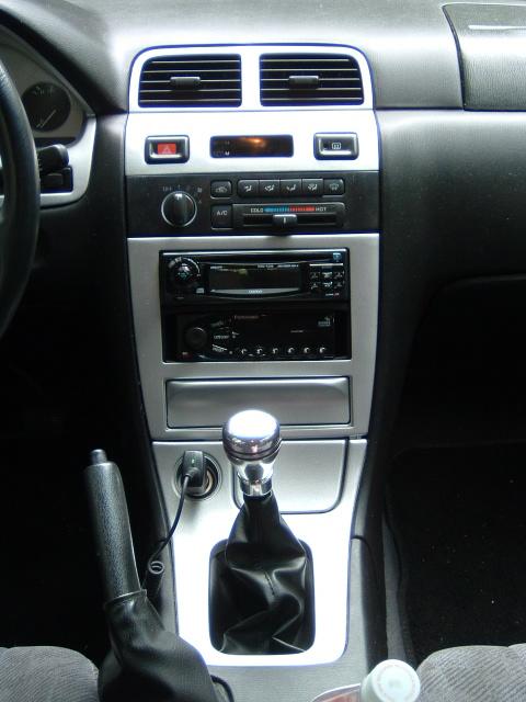
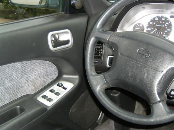
I first started by removing the pieces of the dash that I wished to paint. The front center A/C vents that are attached to the clock, Hazard light button, and rear defrost button was first. Many people will tell you to stick a small screw driver in between the trim piece and the main dash. I’ve found that an old butter knife works better. The wider surface area lessens the likelihood of creasing the plastic. Anyways, stick the knife in there and pry between the two pieces until the center trim piece begins to stick out a little. From there, grab it with your hands and pull firmly. If you hear a loud snap, don’t worry. I’ve yet to remove my center A/C vents without the A/C vent piece detaching from the console trim. When you get it out, you’ll see what I’m talking about. When the piece is loose, disconnect the wiring plugs from the clock, hazards, and defroster.

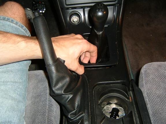
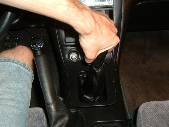
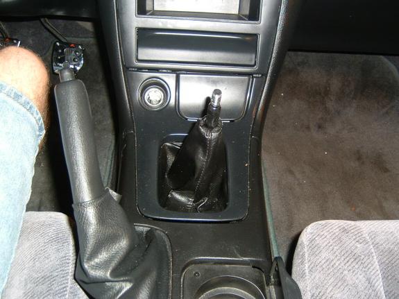
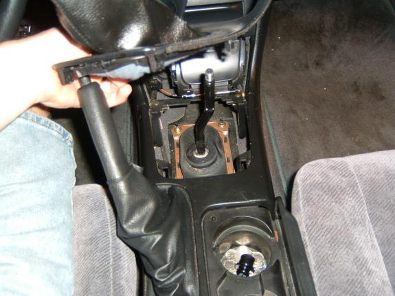
Once the A/C vents are out, move to the lower console trim piece around the gear shift selector or shift knob. If you have an auto (you poor unfortunate souls 🙂 you’ll probably have to do the knife trick again. If you have a 5 speed (congrats) then you can reach under the plastic trim piece near where the shift boot meets the trim. Gently pull up. The piece comes up from the rearmost portion first. It then just tucks up under the main center console trim. If you got a 5 speed, you’ll have to remove your shift knob. For those with factory knobs that have never been removed, this can be tricky. I’ve heard the strap tools from sears work best. It simply unscrews (you’ll just have to trust me. It’s on there good!) Once the knob is off, the boot will come up and off. Unplug the cigarette lighter. You’ll have to push the little release button thingy. The boot sits in the trim with basically clamps and the wire frame. Look at the back of the trim. You’ll see.
The ash tray is next. There is one Phillips head bolt on the left side of the ashtray. take it out. From there, the ashtray pulls straight out. Mine was a real pain, and I actually broke the clip off cause I thought initially it slide to the left. My mistake. IT COMES STRAIGHT OUT. Once that is out, It is time for the large piece where the radio, A/C controls, and that cool cubby hole is.
This is the easy one. There are 4 screws (Phillips head) that hold the large piece to the dash. Once those are out, the whole thing comes out. Unplug the electronics, and you’re good to take everything inside where its clean and air conditioned (I live in TX. This is important).
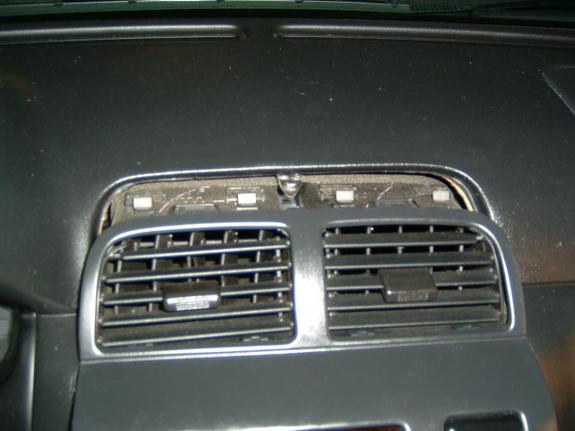
Once inside, its time to remove and dismantle some thing. Take the A/C vents apart from the trim. There are a series of clips that hold them together. Pretty self explanatory. There are buttons on each side of the hazard light and defrost buttons. Push them in and push the buttons out through the front of the trim. There are two screws on the back of the clock display. Take them off, and remove the clock. Now that piece is almost ready to be painted.
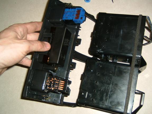
Next, look at the big piece. There are 4 screws on the back of the big trim piece that hold the metal bracket and the trim together. Take those off and separate the two pieces. Set the plastic trim aside. It’s almost ready to be painted. If you want to paint the cubby hole thing, then remove it from the bracket via the 4 screws. You may need to loosen the screws on the radio and A/C to get this out properly. If you take it out, set it aside.
I had manual A/C controls, and it would be extremely hard to paint this piece since it is all one piece, and some part of it are transparent to show the light. If you have Auto Climate control, I believe you can dismantle that piece (remove the buttons and LCD from the main trim) to paint it successfully.
Set the ash try aside.
Last off, set you shifter trim piece aside for those of you with autos. I think it should be ready, unless there is a clear piece in there somewhere. I’m not sure really. For the 5 speed guys, remove the shift boot if you haven’t already done so. It’s simply a wire frame on the back of the trim piece that is clipped in. Really easy.
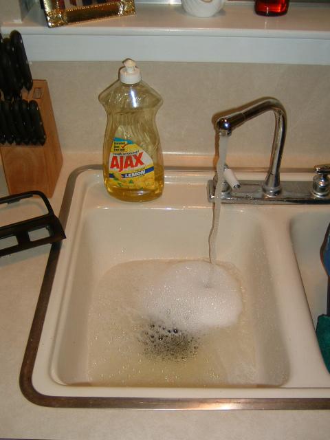
Now lets prep. Take all your pieces. Should just be plastic pieces. I put mine in the kitchen sink and took some liquid AJAX and went to scrubbing. The purpose is to remove ALL the old armor all and other cleaners and stuff that has soaked into the plastic over the years. Mine unfortunately had a dash kit on it, and I had to remove about an eighth of an inch of adhesive. Took me about 4 hours to do just that. 🙁 Once everything is properly cleaned you have the choice of doing the following. I chose to wet sand all the pieces of my dash for a clean smooth look. I used a fine grit sandpaper (cant remember) to wet sand mine. This also helps to remove any armor all etc.
Set the pieces out to dry. Take a lint free cloth to speed this process. Now its time to paint. I used Duplicolor wheel paint (silver) to do my dash. The reason, the wheel paint is made to adhere specifically to plastics, and it is also engineered to resist chipping and scratches.
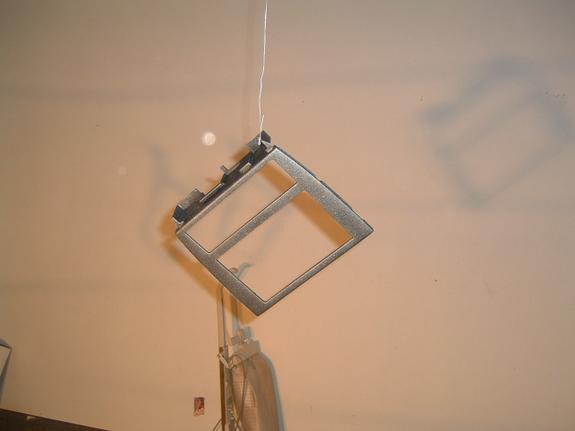
I chose to hang my pieces in my garage via electric fencing wire (commonly found in south Texas garages). That left me a clean place to paint without bugs, dust, wind, etc. Paint the trim pieces like you would anything else. Light smooth consistent strokes. Don’t go to slow or too often or you’ll get runs in the paint. If the paint runs, you’ll have to let it dry, and then go back and wet sand it, and then start all over again or else it’ll look like crap. Patience is the key here. This is a mod that will easily take a full day and maybe two. Put on several coats of good consistent paint in order to obtain a good clean STRONG finish. Some of you may wish to do a coat or two of clear coat. It’s up to you. Some people swear by it, but I didn’t do mine. If you do a clear coat, you will get a glossy finish. I didn’t want that, and due to the paint I used, I didn’t think durability would be an issue. After about 6 months now, I only have two very small scratches in the passenger door handle insert due to my wife’s long fingernails which could have been avoided.
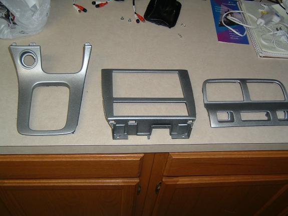
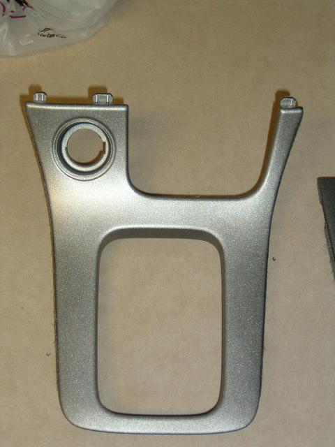
Let the paint dry an accurate amount of time, and reinstall you sweet looking dash.
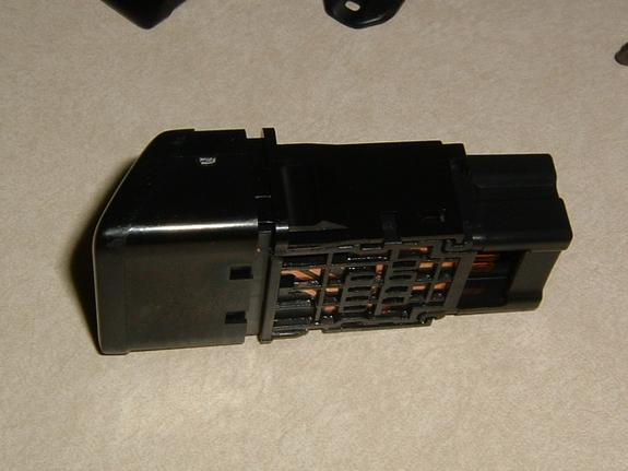
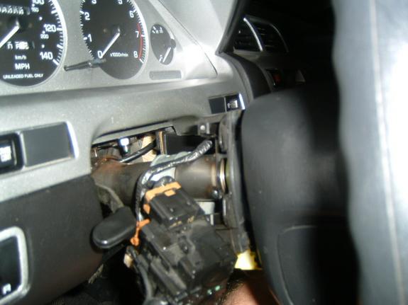
To get to the gauge cluster, start by removing the plastic panel underneath the steering wheel by the driver?s legs. Remove a Phillips head screw from each side of the bottom of the plastic trim. The top of the trim is held on by two retaining clips. Once those are popped out, you will need to disconnect a sensor attached to the back of the panel. Once removed, remove the two 10mm screws that hold the steel plate which is located directly behind the plastic panel.
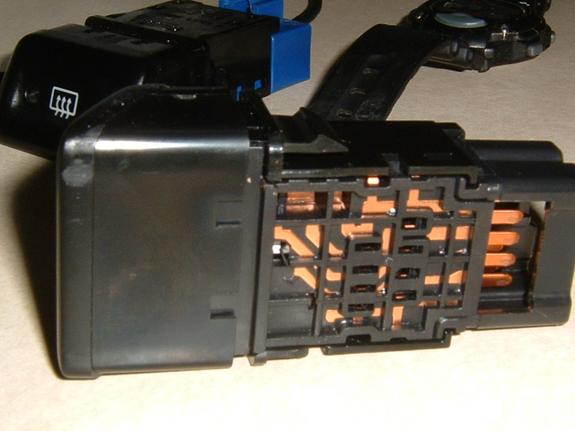
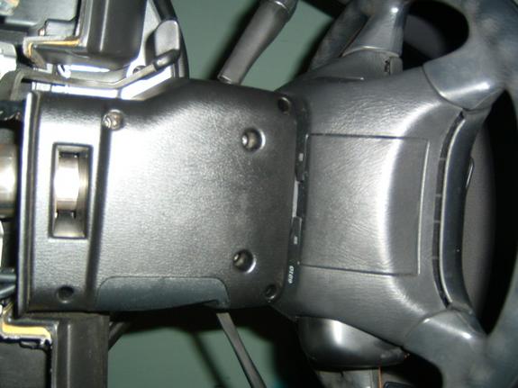
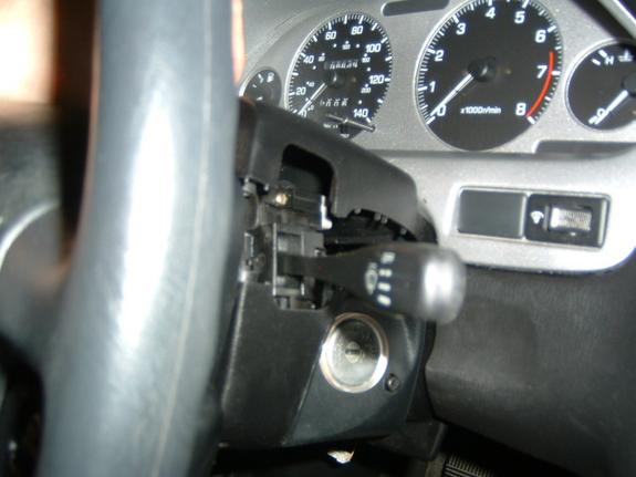
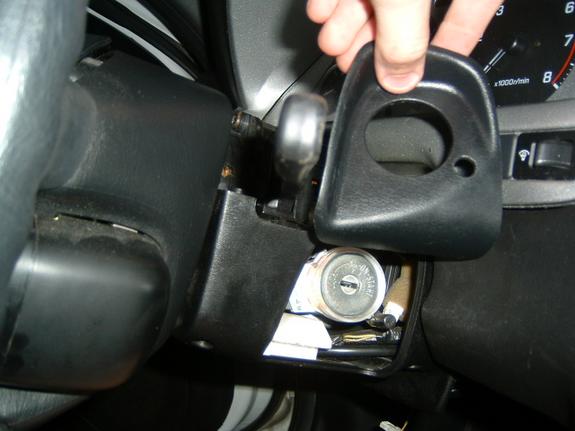
Now remove the 6 Phillips head screws on the bottom of the column. Pull the top piece of trim off the column, and then remove the key hole trim. The bottom plastic trim grips the column, so it will take a good tug. Next remove the wiper stalk and headlight stalk by removing the two brass Phillips head screws from each. Let them dangle out of the way. Now remove the two Phillips head screws from the gauge trim. The bottom is held on by retaining clips. Once this piece is free, unplug the switches that are present. They may be the security LED, the gauge dim switch, and the cruise switch. Once this piece is removed, you can push the switches back out through the front of the trim. Paint the trim if desired.
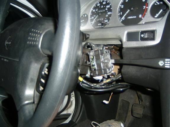
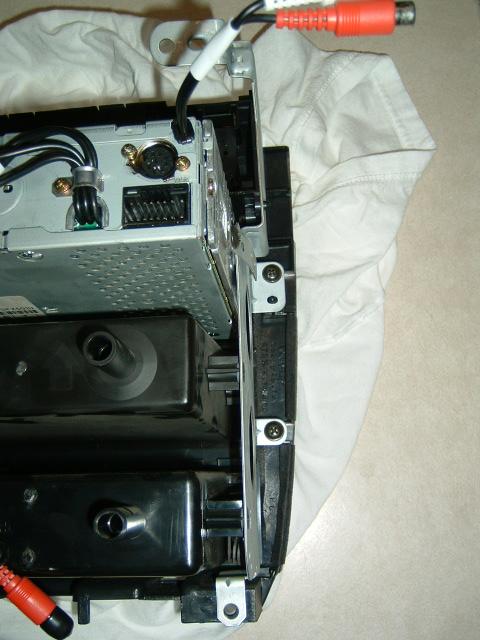
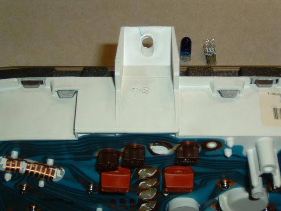
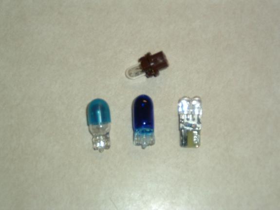
Now remove the three screws holding the gauges to the car. One in the top center, and one in each lower corner. Unclip the harnesses from the back of the gauges. The gauge bezel and the clear lens are simply clipped into place. Take your time removing the two. Once you get the bezel off, you can paint it to match your dash as well. Take you time and don?t break anything. I went ahead and replaced the bulbs in my gauges while I was back there. LED bulbs work OK, but make sure they are wide angle bulbs if you do.

![]()

Member Credit: wariow3
Difficulty:
Easy to moderate.
Knowledge of LED’s + Resistors
Experience with soldering recommended
Items needed:
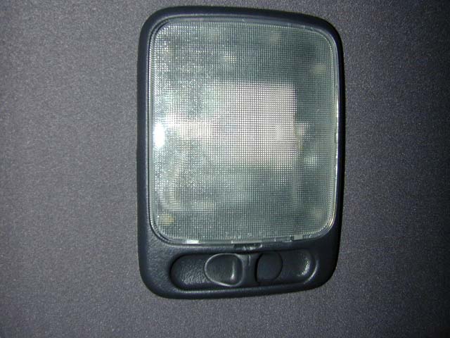
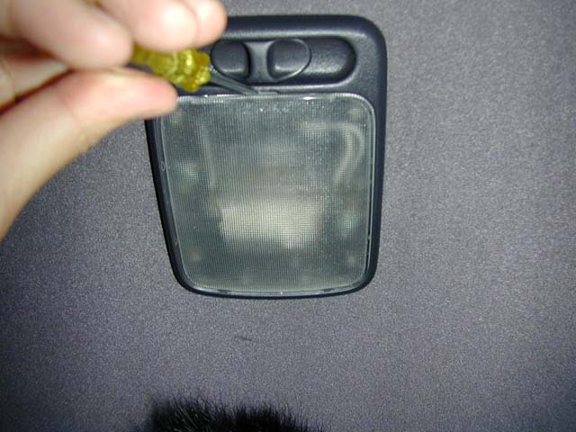
Start by removing the plastic cover off the dome light itself by prying off from the slit near the switch
Upon opening you’ll reveal two philips screws, simply remove those with your philips screwdriver.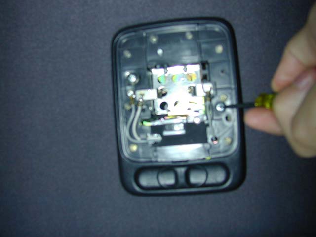
After removing the screws, pull it out from the roof a lil and remove the connections and bring it inside so we can start cooking.
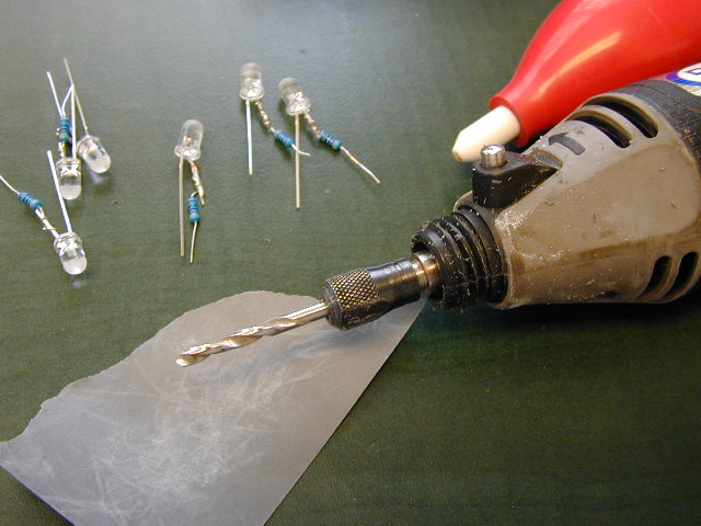
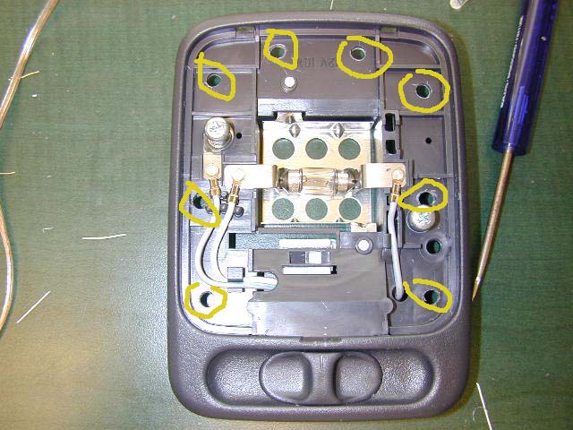
Here we have the dome light opened up. As you can see, I used my dremel and a drill bit and just drilled out an array of holes on the border of the plastic.
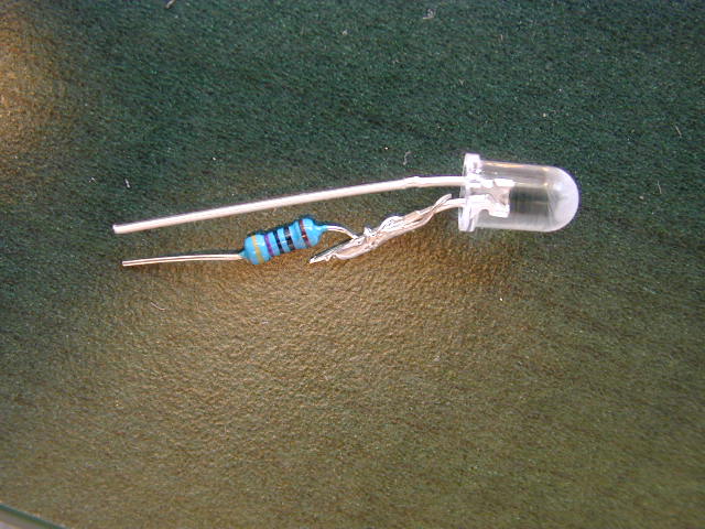
Start making your resisted LED’s by soldering the resistors and LEDs together.
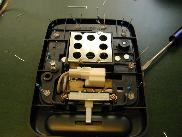
Stick them in from the BACK side of the dome light so that the + and the – of the LED sides are facing a similar way
Use krazy glue on the edges of the LED to secure them in the holes.
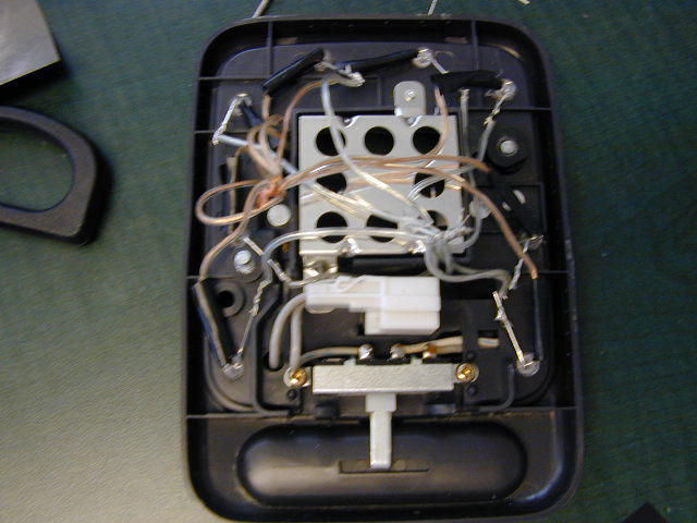
Here’s the tricky and annoying part, using the split speaker wires, Measure the distance of the speaker wire from the led to the center and give it about an inch of clearance.
Connect all the Positive(+) sides of the leds to all one color and solder onto the LED leads.
Connect all the Negative(-) leads to the other color and solder on the leds.
After connecting each color on the LEDs, attach the ends of all the wires into a bunch. Attach another wire on the bunched ends of one color and drag it through a hole to the other side for power.
Use electrical tape to wrap one side of the LED leads so that they won’t make contact with each other.
MAKE SURE NONE OF THE OPPOSITE COLORS TOUCH wether it be the leads or the speaker wires or it will probably blow an led.
The red circled wire is positive and the black is negative. I connect all my Positives to the red speaker wire and all my negatives to a silver speaker wire.
Connect these with solder onto the existing connection.
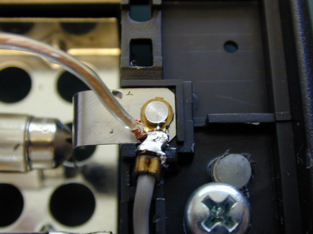
Here’s a closeup of the connection soldered.
Now remove the existing bulb and bring out for testing.
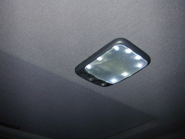
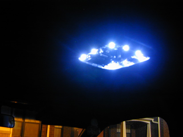
Here’s the finished result. BLING BLING eh? if some don’t light up or none light up at all, check your existing connections and look at your LED’s to see if any have blown. and check the polarity of the LEDs or your wires.
![]()


