I searched around for a bit today, and was unable to locate a guide detailing how to remove 4th gen door panels (most likely similar for other years). This is useful when installing new speakers, fixing window switches, installing car alarms, etc.
This was done on my 95 GXE (5speed Cali if you really want to know) on 3/21/04 while it was snowing outside (Ohio weather is crazy).
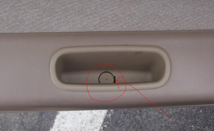
First off, locate small tray pictured here:
Pop off that screw cover, then take the screw out.
You can take out the whole tray if you need to (useful for keeping track of screws), though not nessesary.
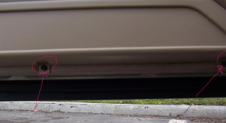
Next locate the two screws on the bottom of the door panel pictured here:
Take both of those off as well.
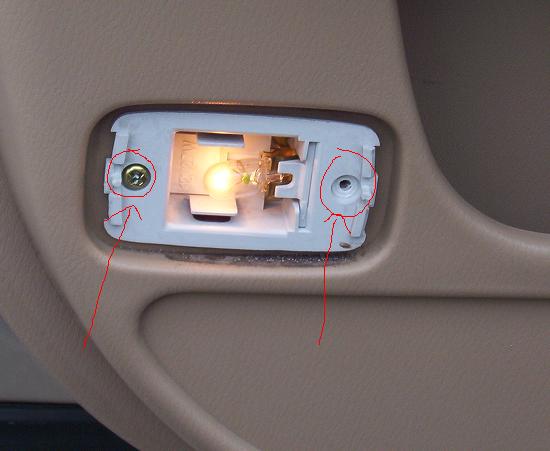
Locate your door light, pictured here:
There is a small conector that attaches to it, and I popped off the plastic cover (take a small flat head to either left or right side of it), and removed the two screws holding it in place. This allowed me to pull it out, giving easy access to the attached connector. Alternatively, you can probably reach your hand under the door after you have completed the next step.
Next, apply pressure all along the door panel, start at the bottom, then do the sides. There are several pop-screws that will pop out with a bit of force. Also, having the window down helps a bit with removing the whole door panel.
The last thing to remove is the doorlock/window switch connector, which can be a little stubborn, be gentle so as to not break it.
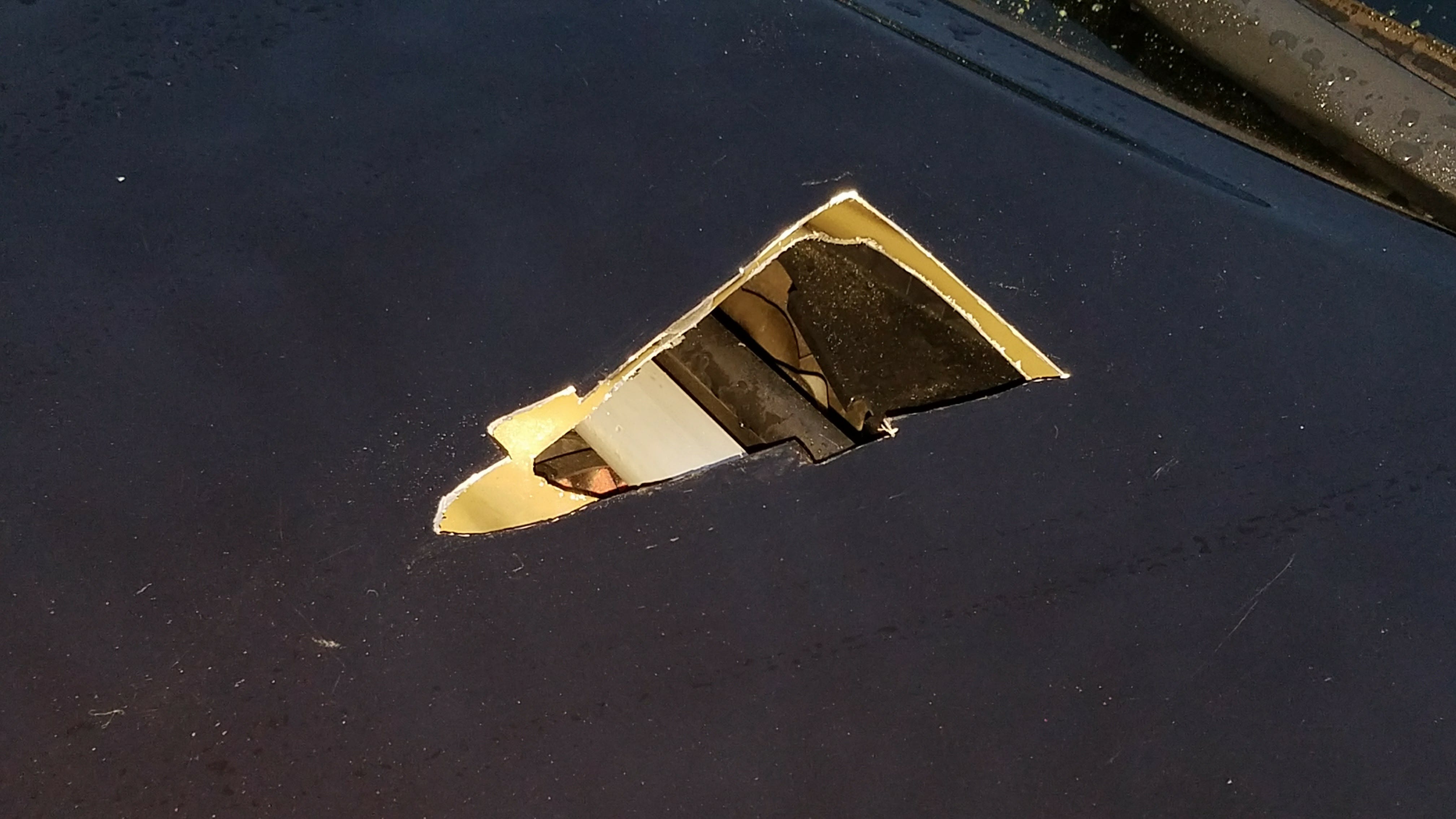
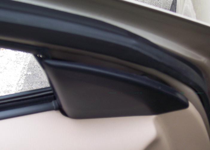
Removing this black piece may also be of some use in particular projects, it easiy pops out with a flathead, shown here:
To reinstall, just reverse the steps. Pop the black panel back in place (if you removed it). Reattach both connectors. Align the door panel on the window lip, then pop the tabs back into place. Attach the bottom two screws, then attact the center screw & tray, replace screw cover, and you are done!
5mm leds ,I used white LED’s( around 4 or more, one for every gauge, more just incase they blow or just dont’ work) I get mine off ebay from the user ctwick or something.
He ships them from hong kong and it’s free shipping. I paid 9 dollars for 25 blue and 25 white leds. Nice and bright and they come with free resistors too!
Soldering Iron (small tip preferred) 10-15 dollars from radio shack
Solder
Soldering flux ( to help stick solder to smooth-surfaced connections)
soldering braid (to clean up excess solder)
Tweezers
Scissors
electrical tape
thin probably 20-22 gauge speaker wire
wire stripper
medium grit sandpaper
Gauges
REMINDER: This will work best with a 97-99 dash. If you have a 95-96 you MIGHT be able to do it but I haven’t tried it so it’s up to you.
You also need to do the 194 bulb conversion for the 97-99 mod.
You can do this mod first and then start the LED needle mod.
This is necessary because we will be drawing power from the bulb light connections.
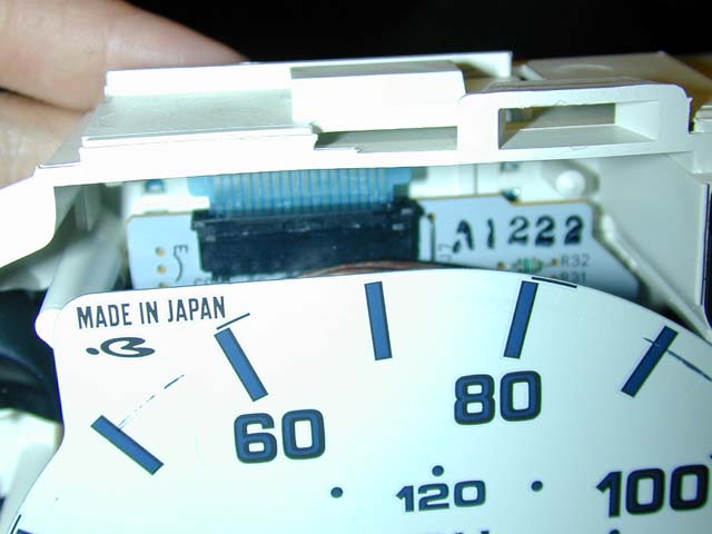
Start by removing the black plastic trim around the gauge by sliding the tabs off the white piece.
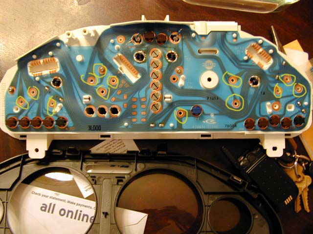
here you see the black trim is removed and the gauges and the back are exposed. Make sure not to mess around with the needles, so handle it carefully.
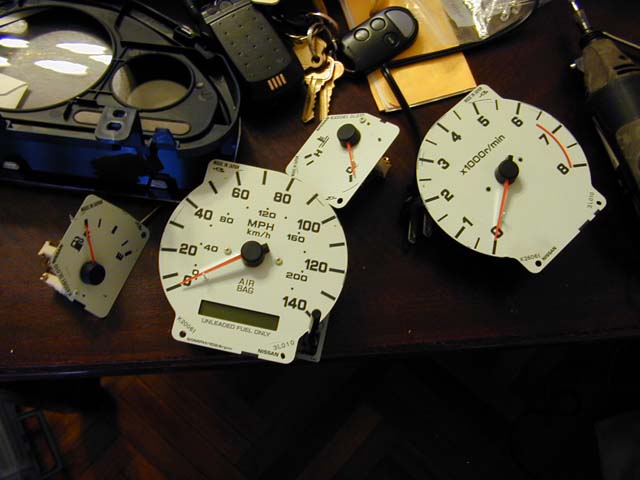
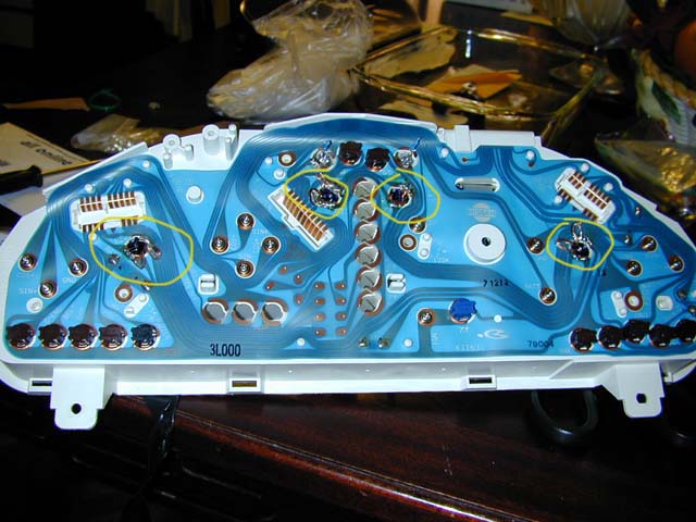
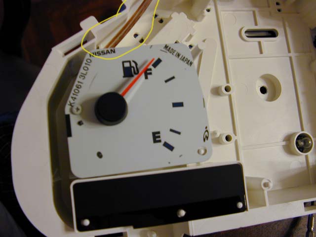
Remove the screws that attach the gauges to the cluster by unscrewing the screws with a screwdriver in the yellow circles. (most of the screws are removed in the picture) Remove each cluster carefully EXCEPT for the odometer(the one that tells you how fast you are going not the tachometer which reads the RPMs)
To remove the odometer, stick a small flathead in the wedge of the black connector and pry up to loosen the connection. After that is done, gently remove the gauge.
Here are all the gauges removed.
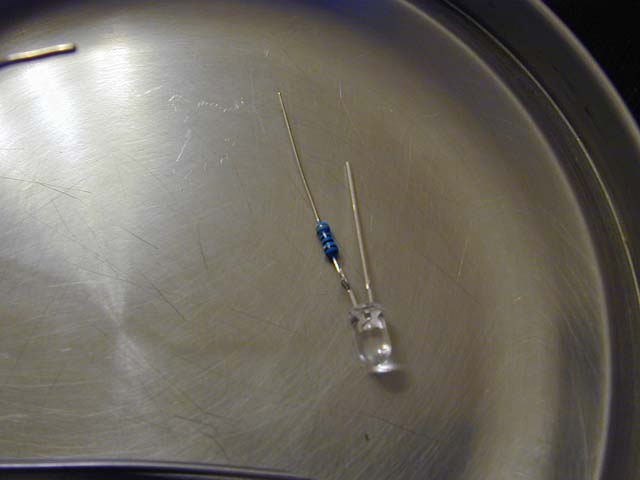
Start making your resisted LED’s. If have LED experience or did any of my how-to’s then this shouldn’t be difficult.
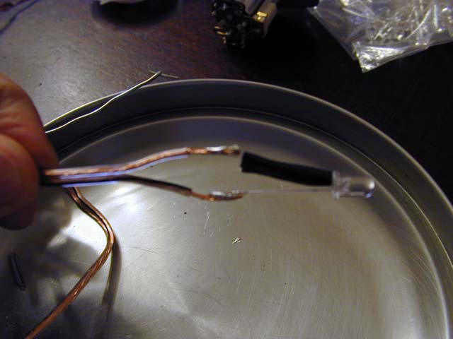
Add the speaker wire connection to the LED’s and solder those on as well give around a foot length of wire. Electrical tape one side fully then bind both sides after one side is fully wrapped.
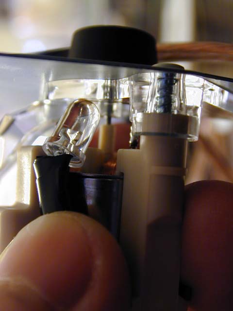
Here’s the tricky part, placing the LED’s behind the gauges. As you can see in the picture, I bent the LED a lil bit to angle it towards the plastic trim but also careful not to get in the way of any fragile mechanisms. after I am satisfied with the placement, (get the LED to point at the center as close as possible) I secure it with some more electrical tape around the gauge
The fuel and temp gauges were the easier of the gauges because there weren’t many objects in the way and just wrapped tape around the edges.
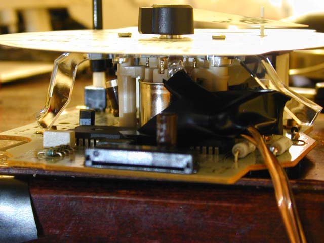
In this pic is the arrangementfor the odometer. Look at all the crap going on in there so there was only really one place to set it and taped it down to the surroundings, again make sure you won’t affect the operation of the gauge itself.
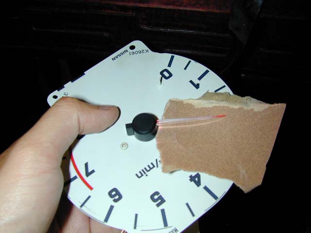
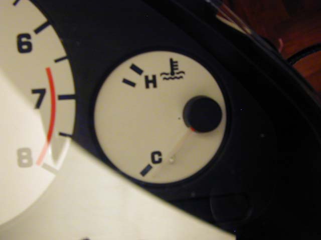
After all the LEDs are pointed correctly and are secured, using medium grit sandpaper, sand from UNDER the needle to remove the red/orange film underneath the needle to make it clear.
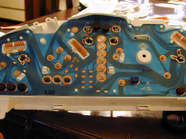
Now we’ll want to make the connections using the existing bulb connectors in the yellow circles.
Before putting back the gauges in the cluster, round the speaker wires neatly through the nearest hole of each individual gauge and then screw back on the gauge.
After each wire is pulled through each hole and each gauge is screwed back on, (REMEMBER the Odometer connection, where you have to put back in the tab. Putting this back in can be a lil tricky but try to get it as inyou can, you can tell when the tabs on the side are touching the black connector and then simply push it down to secure the connection.) it is time to solder on the connections.
Here the connections are soldered on. Make sure the are secure and well soldered. Use soldering flux to easily stick on solder to the copper connections. Remember that the 194 bulbs are soldered on also so make sure they have a secure contact with the same solder also. (NOTE: if you have a 95-96, You might be able to draw power from the twisty thing that holds the 194 bulb. Just stick the wires underneath and twist it onto the connection. If somebody attempts this, please let me know)
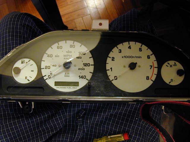
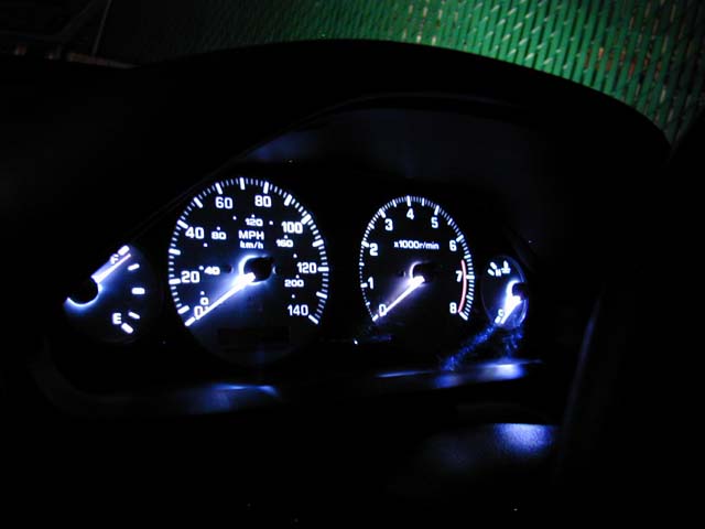
After checking all the connections, it’s time to finally test! Go out and plug in the gauge, remember to plug in the dimmer switch also or the bulbs won’t light up. If an LED or two doesn’t light up, try reversing the connections around and check the soldering. You might not see much during the day but at night, it’s a big difference from the red you used to have.
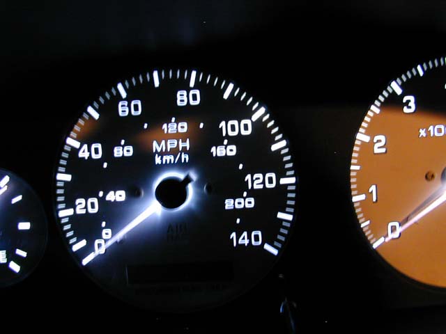
Nice clear needles
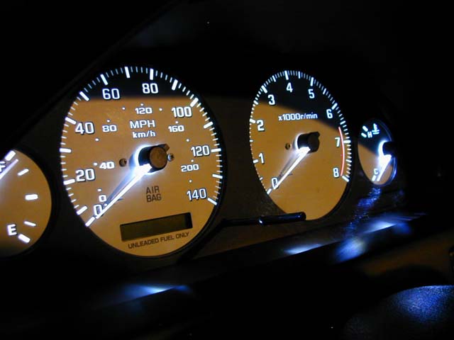
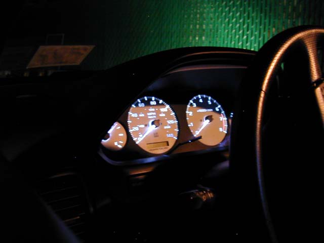
The finished results. Orgasmic if I don’t say so myself. Not that difficult to do if you have some LED knowledge and some common sense. Saved myself 50-70 dollars on intelliglo needles also.
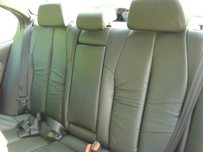
I am going to try my best to explain how to install the newer seats from Gen 5/5.5’s. I installed heated, power front and heated rear seats into my cloth interior 97 SE.
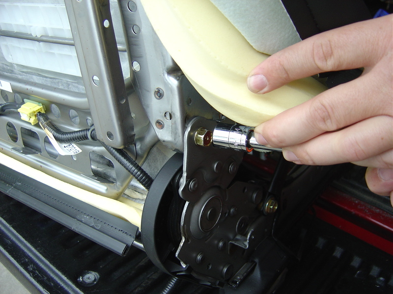
There is 4 12mm bolts holding the seat bottom on. Remove them. Pull seat bottom out of the frame and set aside in a safe place.
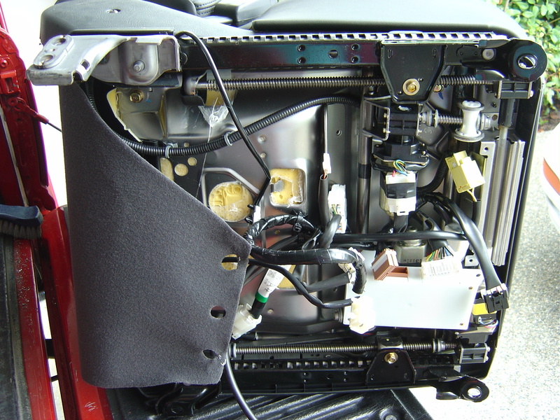
There is 4 14mm bolts that mount the seat back to the recliner mechanism. To get to them, partially pull back the leather. There will be airbag and possibly seat heater wiring to disconnect also. Set aside in a safe place.
For the driver seat, you’ll need to pull the seat memory module and the main harness if so equipped. Set aside for modification. The pass side seat electrics need no extra work and will connect to your A32’s stock power wire.
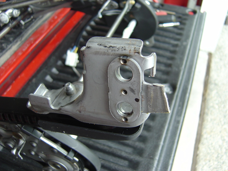
Mark the inboard (tunnel side) seat mounts at the notch and before the radius of the corner. Use a hacksaw to cut a tab, and bend that tab flat.
Finished product of bending.
Drill a hole in about the center of the tab. You will need to double check where the hole will end up, but this pic will give you the idea.
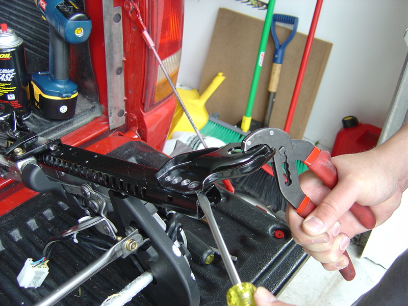
Now you’ll need to drill out the 2 rivets and 2 spot welds on the 5/5.5 Gen seats and break off the outboard side rear bracket.
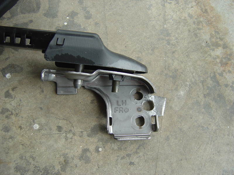
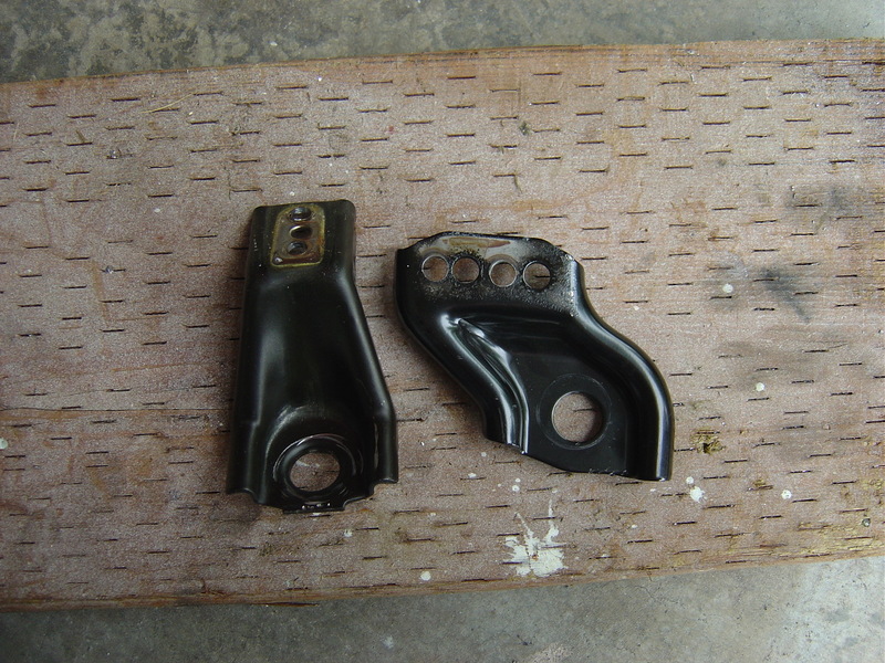
Do the same on the Gen 4 seat, you’ll need the one on the left. Bolt the Gen 4 one to the Gen 5/5.5 rail using the holes you made while drilling out the rivets.
OK, so I left alot of stuff out. I will update this as I get more pics, but this should give you an idea of what kind of work is involved. If you happen to find minty new seats from a Gen 5.5 like I did, you may just want to attempt this.
The rear seats amazingly snap right into place with little mods needed. On my I35 seats, the rears folded down as opposed to how my original seats did not. The I35 seat bottom snapped right into place, and the outer leather pieces bolted into place using the same lower 10mm mounting points as the original seats. The seat backs require latches and hinges to be installed, so just use those parts from the donor car and screw them down with self tapping screws.
Heated seats: My I35 seats are heated front and rear. I am awaiting the Gen 4 center console and switches to arrive before I wire in the seat heaters. I have all 4 switches and harness stubs, so I’ll just tap the power from the factory supply for heated seats, which my car was not pre-wired with. I will detail this after I receive my console.
EDIT: No need for special center console, even a base model has the heater switch knockouts. I just knocked-out the blanks.
Power Driver seat w/memory:
The I35 seat has a memory brain (white box). I taped up all wires, and just supplied power to the +12V and Batt (yes there are 2 sources to the box per FSM) and the GND and SIG GND are connected together to Ground. I connected these wires to the power seat harness that was pre-wired into my car, and voila everything works.
Power pass seat:
Plugs right into the stock power seat harness, no mods needed, same connector.
Power seat power:
There is a circuit breaker that needs to be installed in the driver’s side kick panel. Use your FSM to find it. The CB is fed by the power accesories circuit thru a 30A fuse (all Maximas have this circuit, only Max’s with pwr seats will have the additional breaker)
Seat Belt:
Use the old seat belt latches on the new seats. The 5.5’s don’t work on the 4.
Side Airbags:
If your car has the optional side airbags, make sure to do all work with the BATT disconnected. Feel free to hook up the side airbags to your stock SRS system (if so equipped) I am sure the Gen 4 SRS side airbag system will work fine with these seats.
Disclaimer: I will take no responsibility to any damage done to your vehicle by attempting this mod. I recommend only people with at least some electrical background and soldering skills attempt this. You could very likely blow up either LEDs or your Climate Control by doing things incorrectly. I have tried to write the steps as accurately as possible. If something needs clarification, let me know.
NOTE: If you attempt to use a different LED than what I used (listed below), you will need to re-do the calculations done in Step 7 according to the specs on your LEDs. You may wish to try using Radio Shack’s 2600 mcd blue LED as you should be able to get the buttons to glow brighter (the Radio Shack I went to didn’t have any in stock). I’m probably going to switch to the brighter LEDs when I have the time.
Supplies:
4 Blue LEDs (I used Radio Shack part #276-311 which are rated at 300 mcd’s, handle 30 mA and use 5 volts)
80 Ohm resistor rated to handle at least 1.5 watts of power (or an equivalent combination)
Solder and Soldering Iron
Small gauge wire (20-24 should be good)
Spade-type connectors (optional)
Shrink Tubing/Electrical Tape
Very Fine Sandpaper (I used a 400 grit cloth)
Utility Knife, Wire Cutters, Wire Strippers, Pliers
Assortment of Phillips and Flat Blade Screwdrivers
7/32″ Drill Bit (optional)
Wire Taps (optional)
Step 1:
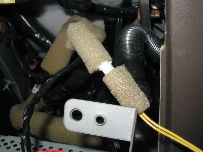
Remove the Climate Control Unit from your car. This is done by following the same procedure you use to remove your stereo. Once you get to the climate control, you need to unplug the tubing and large white connector from the back. A few inches away from the unit the yellow wires out the back will go into a harness that can be undone. On my car, the harness was wrapped in foam.
Now, using a flat bladed screwdriver, remove the back cover from the unit. Using a Phillips screwdriver, carefully remove the 4 bulbs from the unit (they are the 4 brown plastic things with a Phillips pattern on them). To remove them, twist them with a screwdriver and then you can pull them out (or tip it upside-down and they will fall out). DO NOT LOSE THESE, you will need the brown plastic pieces later.
Step 2:
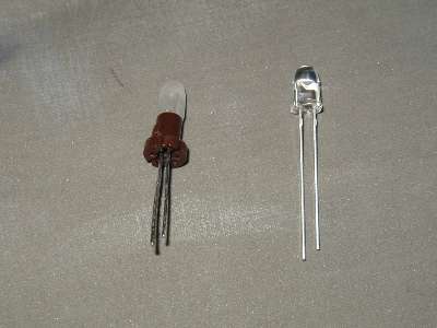
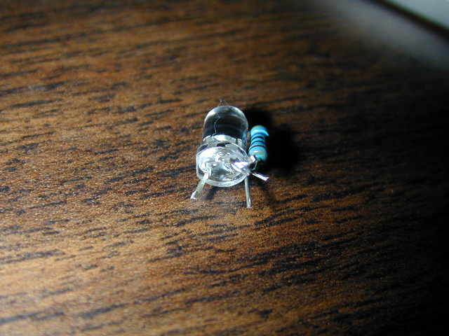
Take the 4 LEDs you have and use the utility knife to trim off the little ring around the bottom. Once you have trimmed off enough, the LED will slide smoothly in and out of the holes left in the circuit board when you removed the original lights. Once you have done that, use the sandpaper to roughen the surface of the bulb. Incandescent lamps emit much more light to the sides than LEDs, so by using the sandpaper to roughen the plastic casing, much more light will be diffused to the sides of the bulb. Below is a comparison of the original LED (right) and one after I trimmed and sanded it (left), both lit and unlit. NOTE: Keep track of which side of the LED is the positive/negative lead. If you wire it up backwards, the LED won’t light up. The negative lead is the one that is attached to the little dish inside the LED.
Step 3:
As shown in the above picture, you now need to remove the original lamps from the brown plastic holders and replace them with LEDs. To remove the original lamp, unwrap the leads from the bottom and simply pull the lamp out. The leads from the LED should fit into the holes already there, and you can use a dab of glue to hold the LED on the holder.
Step 4:
You are now just about ready to put the LEDs into the unit. If you notice, right now the LEDs wont stay in the board because the plastic holders won’t tighten. You can solve this by putting a thin piece of paper between the circuit board and the holder. I used a 7/32″ drill to make the hole, but I’m sure there are other ways. Make four little squares with holes in the middle, and you can now put the LEDs in the board.
Step 5:
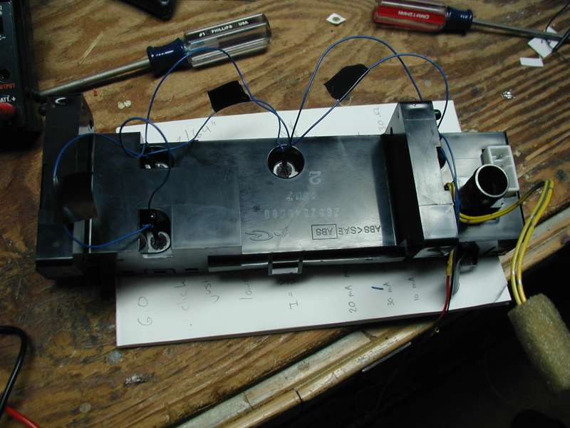
This step is where I got lucky. The LEDs need to be wired together in parallel. I chose to put the wires outside the unit, as there are already holes in the back of it. I had some small jumper wires that already had connectors that fit over the leads on the LEDs. If you are not that lucky, you will need to do some soldering in this step (bear in mind if you solder here and ever want to take the back off the climate control at a later date, you will have to unsolder everything). You need to solder the negative leads of all the LEDs together and do the same with the positive leads. MAKE SURE you don’t mix these up. If you have red and black wire, that is good (I only had red wire, so I used electrical tape to mark the negative one). Make sure you leave some extra wire on the ends. Below is a picture of my unit after I put it together and attached wires to the leads (click on it for a larger version).
Step 6:
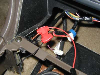
Now that you’ve finished with the climate control unit, you need to find a power source in the car. You’ll notice that we didn’t use the circuit board to get power for the LEDs. This is because the power supplied to the original lights varied with the dimmer. In order for the LEDs to be at the optimum brightness, we are going to need a constant power supply. I decided to get my power from the cigarette lighter, since that only receives power when the car is turned on. However, this has the effect of the climate control lighting up even if the headlights are off. I used some wire taps I got at Radio Shack to grab some power. Below is a picture of the taps when they are in place. You will want to get two more pieces of wire to use here, and different colors would also be useful. If you don’t have wire taps, you could use solder here instead. Be sure you find out which wire is positive and which wire is negative (the one with more black should be negative, but you might want to test with a multimeter to make sure).
Step 7:
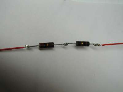
Now its time to use the resistor(s) you bought. Here’s how I decided on 80 Ohms: The car/cigarette lighter provides 12 volts of electricity, and I measured the LEDs as using 4 volts. That leaves 8 volts that have to be used in our circuit. You may also remember that our LEDs are rated to handle 30 mA, so to be on the safe side we’ll load them with 25 mA (we don’t want to blow them out). Also, since there are 4 LEDs, we end up with a total current of 100 mA (25 x 4) or .1 Amps. Since I=V/R, we end up with .1=8/R, or R=80 Ohms. The resistor also should be rated to handle at least 1.5 watts. We will be putting about .8 watts through it (P=I^2 x R or P = .1^2 x 80, so P = .8), and we don’t want it to get too hot. I did not have an 80 Ohm resistor, so I used a combination of two 1-watt rated resistors in series to give me about 76 Ohms of resistance. This puts a current of just over 26 mA through each LED, but it is still under the 30 mA limit. Below is a picture of the resistors I used.
NOTE: DO NOT FORGET the resistor. If you do, you will fry your LEDs. Also, you should be using a resistor for each LED, but since every LED I used is the same type, they should share the load equally, and I simplified the circuit by using only one resistor.
Step 8:
Now you need to connect wires together, and not forget to use the resistor! We have a positive and a negative wire coming from the climate control, and we have a positive and a negative wire coming from the cigarette lighter. We also have an 80 Ohm resistor. You could solder everything together at this point, but that means if you ever want to take everything apart, you’ll have to do more soldering. First, attach the resistor to any one of the 4 wires (it doesn’t matter, as long as it is between the power source and the LEDs). Now you need to connect the positive wires to each other, and do the same to the negative wires. I used some spade-type terminals to do this so that I can easily disconnect them if I need to. (sorry, no pic here).
Step 9:
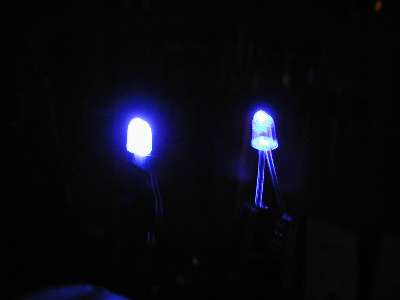
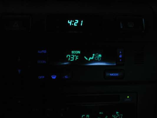
Now, you’re finally ready to put everything back together. You may want to test it before you do that though. Make sure your car is somewhere dark (the lights are really hard to see during the day) and turn your accessories on. The buttons on the climate control should now glow blue. If they don’t, make sure none of your connections came undone. If you see smoke and/or smell something funny, immediately turn off your car and hope you didn’t destroy anything. (I was lucky 🙂 If the buttons glow blue, then go ahead and put everything back together, and next time you’re driving at night, admire your newly re-lit climate control 🙂
This is a how-to to change the current lights in the Hazards and Rear Defroster buttons. This application is for 95-99 Maxima’s but might work also for other max’s and cars. Thanks to JackBauer for his help on the hazards and rear defroster.
Difficulty:
Easy to moderate.
Knowledge of LED’s + Resistors
Experience with soldering recommended
Items needed:
Small flat head screw driver
Small Phillips screwdriver
3mm + 5mm leds ( around 10-15, more just incase they blow or just don’t’ work) I get mine off eBay from the user ctwick or something.
He ships them from hong kong and it’s free shipping. I paid 9 dollars for 25 blue and 25 white leds. Nice and bright and they come with free resistors too!
Soldering Iron (small tip preferred) 10-15 dollars from radio shack
Soldering braid 99 cents from radio shack (use to suck up excess solder)
Tweezers
Scissors
Electrical tape
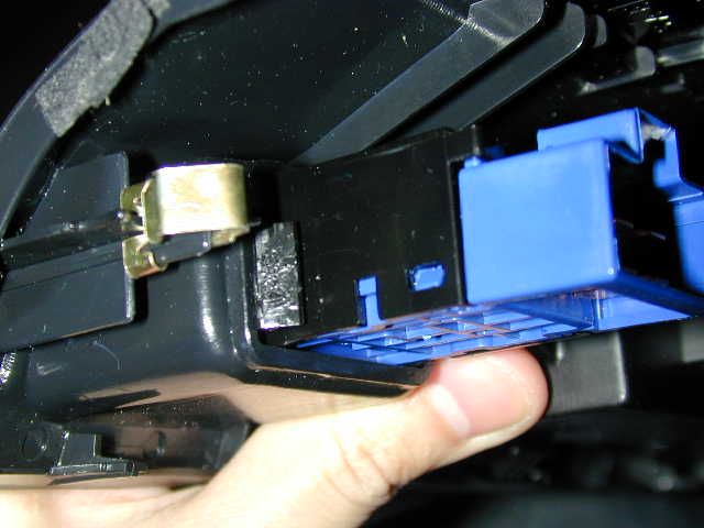
Hazards and Rear Defroster
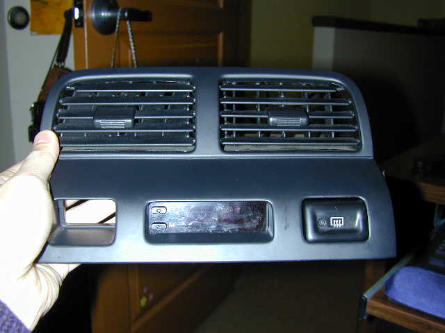
Here’s the center vent area of the dash taken out. It’s pretty simple. If you’ve ever installed an aftermarket stereo, you should be able to take this out with ease. Just pry at the bottom right corner and move to the left corner and it should pop out. Slowly pull it out. Remove the plugs from the back and bring the unit inside. Here’s a front shot of the unit. I removed the hazard already. They come out the same way.
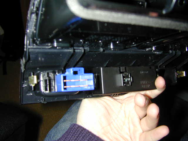
Look at the back of the unit.
On one side of the hazard or defrost switch is a wedge.
Push this thing in with your fingers or a flat head until the unit goes in a little bit. Then with all your strength, push the damn thing out from the back.
It seems like you’re going to break something but you’re not. Just push at the base with your palm, it should come right out.
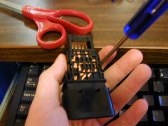
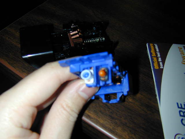
Here’s the switch. Stick your little screw driver on each and slowly pry it out.
Here’s the switch apart
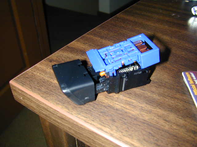
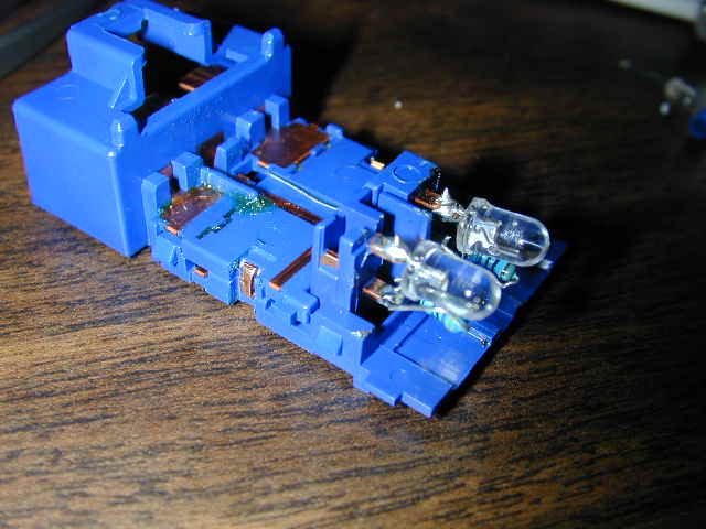
There are two bulbs for the hazards and one on the hazard. You will to replace these with 3mm leds. You will need to solder resistors on them or they’ll blow.
The defroster is the blue one on top and the hazard is the black one on bottom.
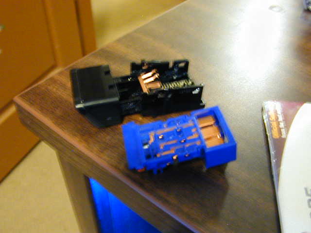
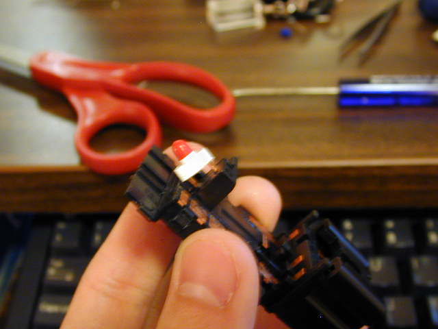
You will see that the current bulbs are in rubber housings, we won’t be using these. We will solder the LED’s with resistors right on the copper connections.
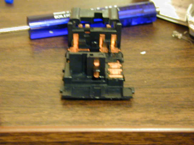
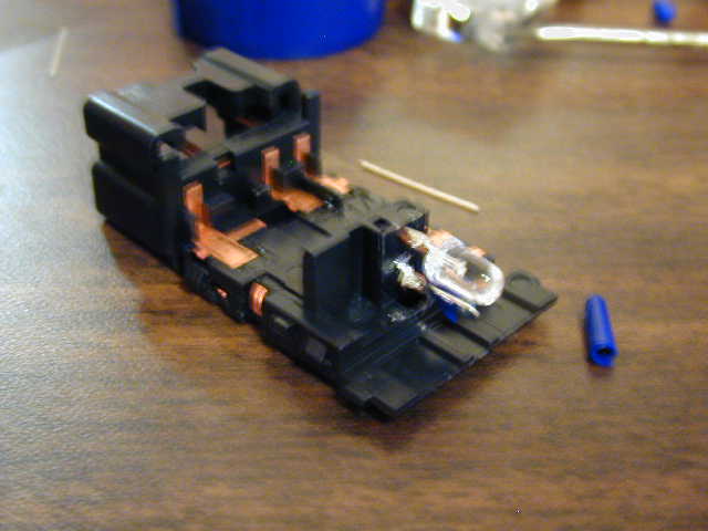
Use your tweezers and remove the housings and you’ll have the bare connections.
Notice the two prongs. The top prong is the NEGATIVE(-) and the bottom prong is the POSITIVE(+). They’re the same with each switch. You will need to match the connections to your LED’s. To find out which connection is positive, look inside the led. The smaller piece inside is positive and the larger piece is negative. So you will have the bigger piece with the top prong and the positive with the bottom prong.
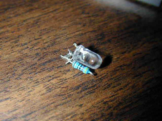
Here’s how I soldered my LED’s to my connectors. (note: I used 5mm because I did not have 3mm’s at the time, I recommend using 3mm because they are easier to work with and product as much amount of light as 5mm)
Solder the one end of the resistor to the positive side. After soldering the positive led lead to the resistor, electrical tape the part where the led connects to the resistor. We’ll be connecting the other end of the resistor to the positive (bottom) prong and the negative LED lead (the one not connected to the resistor) to the negative (top) prong.
Solder does not really stick the copper prongs so we’ll have to put solder on the prongs before putting the LEDs on. Use your soldering iron and grab some solder up and just “paint” the prongs with solder until they stick. After the prongs have some solder on it, you can solder the leds on it. Remember, resistor to bottom and LED lead to the top. MAKE SURE THE CONNECTIONS DO NOT TOUCH OR IT’LL BLOW THE LED OR CAUSE A SHORT.
Pics of it soldered on.
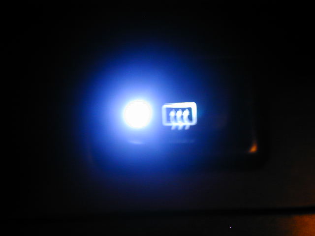
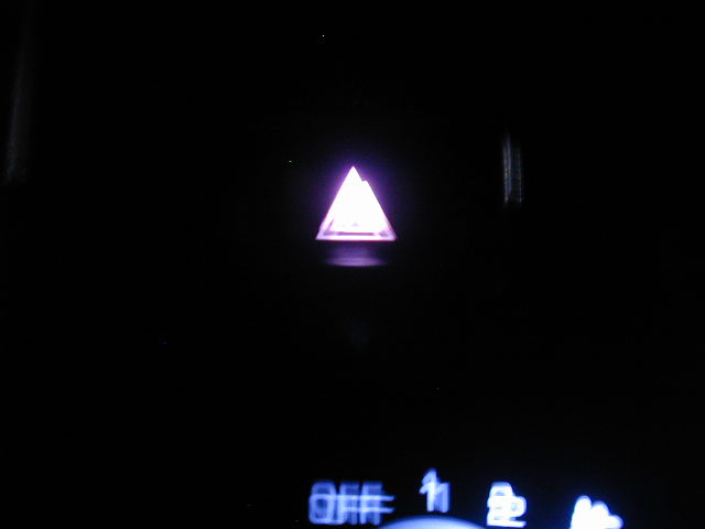
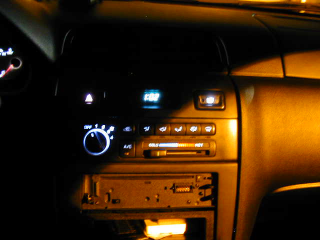
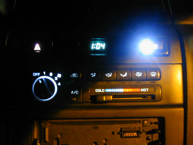
Reassemble the unit but don’t put it back into the vent piece yet. Go back to the car and test if it works. Remember: The hazard on led will work only if the ignition is switched on. If they work, good. If not, check the connections and see if they are touching or not or if the connections on the prongs have come loose. Here’s some pics of it installed.
Disclaimer: I am not responsible for whatever happens to you or your vehicle.
The key to this install is find the wire (negative ground) on the stalk that controls the lights. Here is the deal, the ground isn’t active until the headlights are activated in return provides the ground for the coil on the relay. The two positives on the relay are always hot. We can get past that by putting a relay on the stalk that activates ground when the driving/fog light switch on the stalk is activated. (Please beware that the lights will be on when the high beams are activated).
Relay Location
Next, the relay layout.
Here is a small outline of what has been and will be done:
1. Locate the Relay (Done)
2. Fab a 1/2 (Heat shrunk) wire extension from the relay to the original
socket (with female recept connected to the relay and male that plugs
into the original relay socket. The relay holder is soldered into the
board so you cant snip or tie a wire into the ground peg of the coil (Done)
3. Find the two wires on the stalk that goes to/from light controller. Snip
those two wires and ground one. Connect the other to the negative
(Coil) of the relay that will be placed between the ground of the stalk
and main relay.
This is what will happen:
a. You turn the ignition on. The ground is closed going to the
main relay but not activated until you twist the stalk,
grounding the coil of the main relay which inturns
make the fogs pop on. In that moment, you will then clean
your pants after all the excitement that you will experience
for completing this project
1. First, remove the three screws from underneath the steering column cover
2.Next, press the tab on the top and bottom of the stalk and pull towards the door
3.Remove the two screws from the stalk cover and lift the cover from the stalk
5. Next, you would stage your internal relay and attach wires as illustrated. I used a relay to only allow me to turn the fog/driving lights on while the key was switched to either the ACC or the on position due to the fact there is no alert to let you know if the lights are on if you turn the car off (drained battery)
6. Here is a picture of where the fog/driving lights relay is located in the fuse box under the hood.
I attached extensions that stretched from the relay to the relay holder. I did this because unlike the other generations, the fuse holder is soldered on the circuit board, not allowing you to tap into the wires.
4. Snip the Blue and green wire (04 6th gen) and solder one wire that will reach the relay in the fuse box and another that will be grounded to the column (shown in second picture.
The first step is to remove the grill. The plastic fasteners are easy to remove. If you have two small flat blade screwdrivers, like I didn’t have, you put each one on one side of the center part and pull it up. Then grab it and pull the whole fastener out. Put the grill aside somewhere where you won’t step on it.
Now its time to remove the whole front bumper cover. You will need a Phillips screwdriver and your small flat blades. Start on either side of the cover. First you need to have access to some of the fasteners and screws. These are hidden behind the fender well plastic covers. Remove the fasteners that hold the fender well plastic. Remove enough of them that you can pry it open to get your arm in the TIGHT space to remove the screws.
Once you get the fender well trim open, there are two screws that hold the cover on. They are hard to get at, but try. Unscrew the two screws. Then go underneath and see many fasteners that hold the underside plastic tray to the bumper cover. These were harder for me to remove. But I got them undone. Now do the other side.
The front cover drops down exposing the lights. These are held on by 10 mm screws. Find them and remove them. Here is a pic of the car with cover removed and one headlight out:
Scary, but its ok. The headlights are HEAVY so be careful. I pre-heated the oven to 225 degrees. Also, the area I was working in I wanted dry. So I cranked up the floor heater to 75 and really dried out the air.
Unscrew and remove the turn signal light. This is the easy part. Next, remove the metal box from the assembly. There is a bag of desiccant under the box inside. Remove it too. Unscrew the headlight cover and remove the wires from the cover. Unscrew the 4 screws that hold the headlight in place. Magnetize your screwdriver to help you. There are two other screws that hold a metal plate in. Loosen those and remove the headlight. Here is a pic of the headlight:
Put it in a plastic bag and seal it. Do NOT touch the bulb. Handle this as little as you can.
The fog light is difficult to remove. Unscrew one of the screws holding this spring wire in place. Carefully remove the spring and remove the bulb. Here are pics of the fog light:
Remove all brackets and anything with a screw. Do not touch the headlight adjustors. Now its time to bake it – 225 degrees for 15-20 minutes. Here is a pic of the light in the oven:
Remove light assembly with glove and use a putty knife to CAREFULLY pry apart the cover from the assembly. Do it cleanly and keep the sealant intact if u can.
Remove the chrome trim from the clear cover by unscrewing two screws. Here is a pic of the chrome trim:
Sand it with 1000 grit wet sand sand paper under running water until the chrome is scuffed. Tape the orange reflector. I tried to remove it and BROKE the chrome trim. Here is a pic of that disaster: Next, prime the trim. I used black Plasticote from Pep Boys. I primed the DRL lense because I was not going to use it. Its up to you if you want to or not. Here is a picture of it primed:
Then I painted it with gloss black paint using the Plasticote paint. I clear coated it also, I waited about 15 minutes for each coat to dry. Here is the trim after clear coat:
Now assemble the trim in the cover. Bake the assembly again for 15 minutes and put the cover back on. I used a damp towel to clamp the cover back on the light. I waited until the light assembly was totally cooled down before I put the headlights back in. Use the other light to help you to put back the lights and wiring.
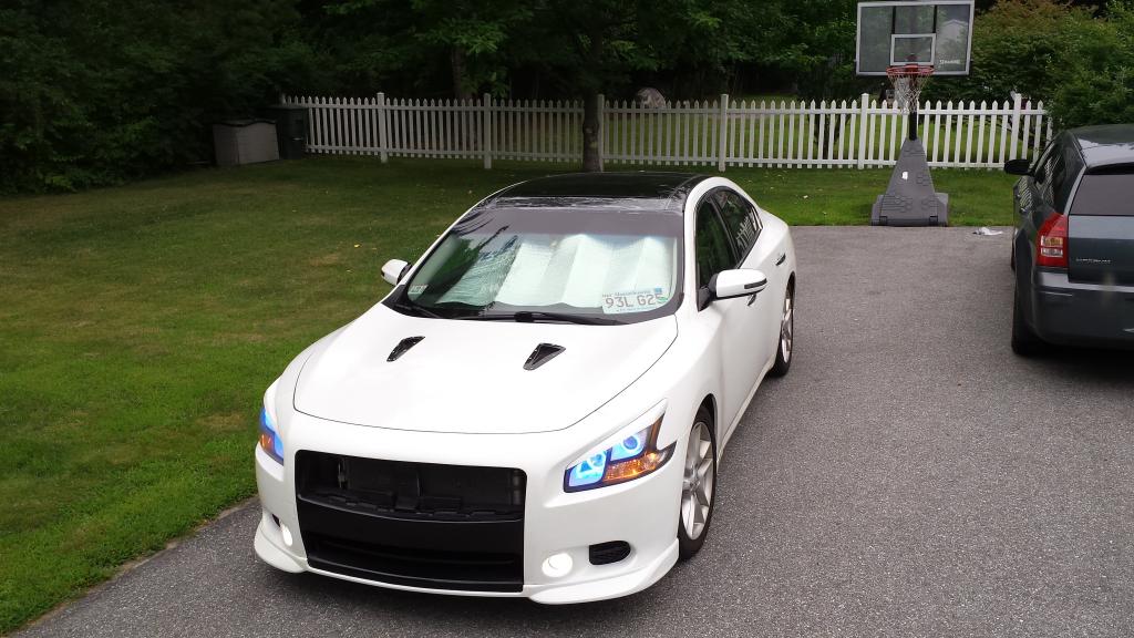
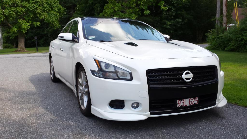
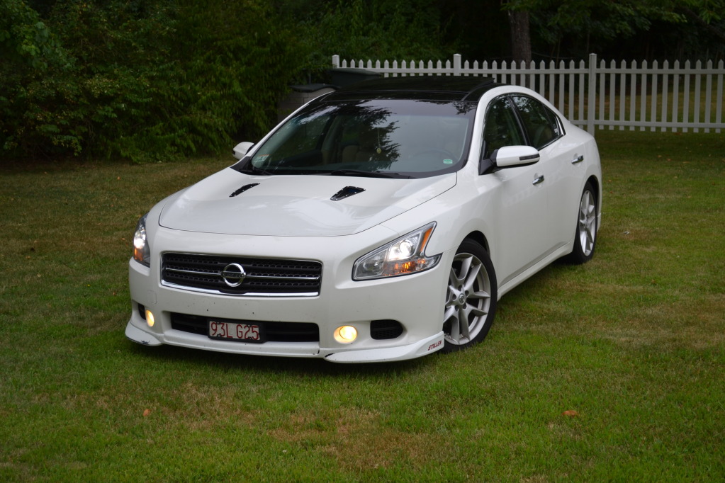
Here is a picture of one light completed next to the other one:
Big difference, especially in person. The glare from the camera doesn’t show how nice the darkened light looks.
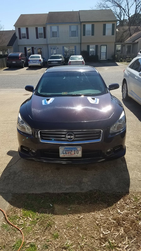
Do the other light and then install the lights in the car and reverse the order of removing the bumper cover and grill. Here are pictures taken after the lights were installed:
Before/After
A couple of tips:
Let the oven get completely preheated before putting the cardboard in. Make sure there is no tape on the piece of cardboard you use. Use the 2nd from bottom oven rack position.


 Here is a small outline of what has been and will be done:


 Scary, but its ok. The headlights are HEAVY so be careful. I pre-heated the oven to 225 degrees. Also, the area I was working in I wanted dry. So I cranked up the floor heater to 75 and really dried out the air.
 Put it in a plastic bag and seal it. Do NOT touch the bulb. Handle this as little as you can.
 Remove all brackets and anything with a screw. Do not touch the headlight adjustors. Now its time to bake it – 225 degrees for 15-20 minutes. Here is a pic of the light in the oven:


 Next, prime the trim. I used black Plasticote from Pep Boys. I primed the DRL lense because I was not going to use it. Its up to you if you want to or not. Here is a picture of it primed: