Follow the instructions below to remove your door panels.
Front Paneling
 Rear Paneling
 Roof Paneling

![]()


Follow the instructions below to remove your door panels.
Front Paneling
Rear Paneling
Roof Paneling
![]()

Member Credit: chrisaust
First, this is fairly easy once you figure it out the first time. Here are my step-by-step tips to get access to the gauges.
****IMPORTANT NOTE BEFORE YOU BEGIN****
If you plan to remove the needles, you’ll need to remember how to put them back on so they are accurate. This may require you to drive down the freeway or a straight stretch of road at a certain speed, noting speed and RPMs at that speed (ie if your RPMs are 3,000 at 80mph, get your friend to set their cruise control to 80, pace them and set your own cruise control and push needles back on at 3000 and 80mph respectively). Also note fuel level and normal car operating temp. After removing needles, it may be easiest to put speedometer and tachometer needles back on while driving. Get a friend to set their cruise control at your specified speed, so you can be pacing them and place the needles back in the right position.
1. Need the following tools: Phillips screwdriver, flat-head screwdriver (or preferably something thin and plastic), and socket wrench only if you need to disconnect battery to work on electrical system.
2. Underneath the steering wheel there are 3 screw holes… Remove these screws with Phillips screwdriver.
 3. Adjust the steering wheel all the way out and down. Inserting flat-head screwdriver in between two plastic pieces on the right side of the steering wheel where the windshield wiper knob is. Carefully pop apart plastic housing surrounding steering wheel and set aside.

 4. Remove plastic covering over gauges. Using flat-head screwdriver or thin plastic, slide under top middle plastic piece and slowly lift up to pop out. Then slide under each piece on left and right, pop out front part first, then lift and pull towards you.


 5. On top of gauge cluster is one single screw, remove this
 6. Under gauge cluster are two hidden screws, unscrew both but don’t remove, it’s easier to pull out gauge cluster and screws will come out with it, then you can take them out.

 7. Gauge cluster has several clips holding it together… using flat-head screwdriver, carefully life these clips off their tabs. Don’t lift too much, they’ll break off VERY easily (I broke 2). Once these are off the tabs, the gauge cluster cover comes apart and you are left with the bare gauge face and needles.


 **BEFORE CONTINUING, READ IMPORTANT NOTE ABOVE**
8. To remove gauge face, grasp black needle center and pull out. Some may require using needle-nose pliers and some force. Don’t SQUEEZE too hard, but you’ll have to use one hand to hold gauges and pull needle out with the other hand.
 9. Gauge face is just stuck on with glue, so you can peel this off if needed. You then have easy access to LED bulbs behind (in case you want to change their color).
 10. To put back together, place needles back on in correct positions. Test these while driving before putting cover back on.
11. Put cover back over gauge face and snap clips back into position. Insert two lower screws into their holes, then push the whole gauge cluster back in position. Screw in two underneath screws, then top screw.
12. Pop two left/right cover pieces back into place, then center cluster cover.
13. Place steering wheel plastic covers back into position and snap together. Screw back in three screws underneath steering wheel column and re-adjust steering wheel position.
That’s it! Not too hard, and only takes about 5 minutes if you have to do it again. Getting needles back into correct position is the tough part, something I need to RE-do while driving as I suggested above. Good luck!
**NOTE** If you did want to change the LEDs in the gauge cluster, it only looked like there were about a dozen, not as many as the information screen, so it wouldn’t be TOO hard of a job. I might just look into it!
![]()
")
Member Credit: EddyMaxx, Blaxima06, Jsmithsole
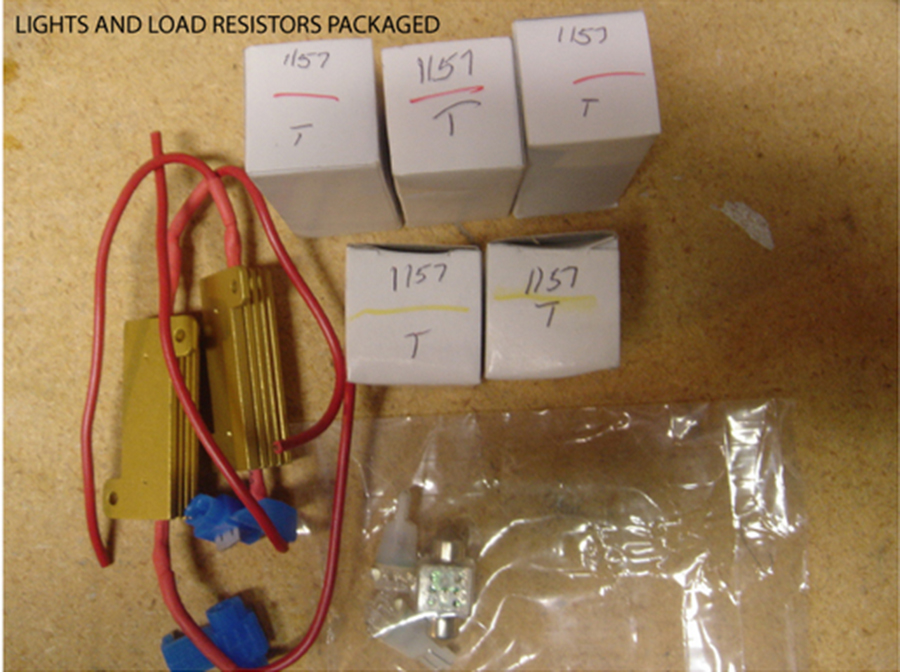
If you are experiencing hyper-flashing after installing Ezkoncepts LED Tail Lights, LED Turn Signals and/or Switchbacks, then you will need to install resistors to eliminate it. You can choose to either install them directly on your tail lights or headlights. It’s up to your preference. Both methods are listed below. Most members noted that the headlight version of the how-to was much easier.
What You Need:
Note: Each side covers front and rear (up to 4 led turn signal bulbs total). For turn signal led bulbs, the equalizer must be spliced across the – ground wire and the + turn signal wire feeding each led bulb.
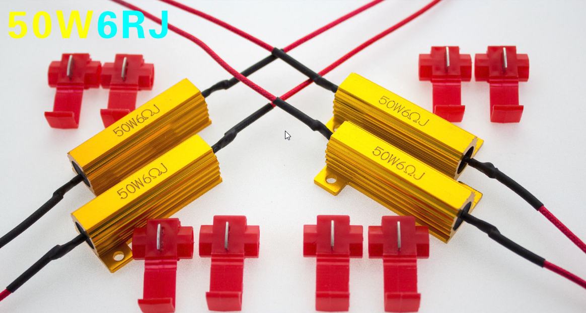
Where to Get it: http://r.ebay.com/eAe1VF
Price: $6.49 (Each) x 4 *(as of December 2017)
—-
General Information:
The load resistor simulates the resistance of the incandescent bulb and restores the turn signal to normal operating function with the led.
Note: When removing the taillight assembly, you do NOT just pull out the red glass. The painted frame portion between the glass and trunk lid is a part of the taillight assembly.

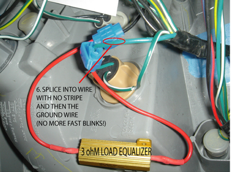
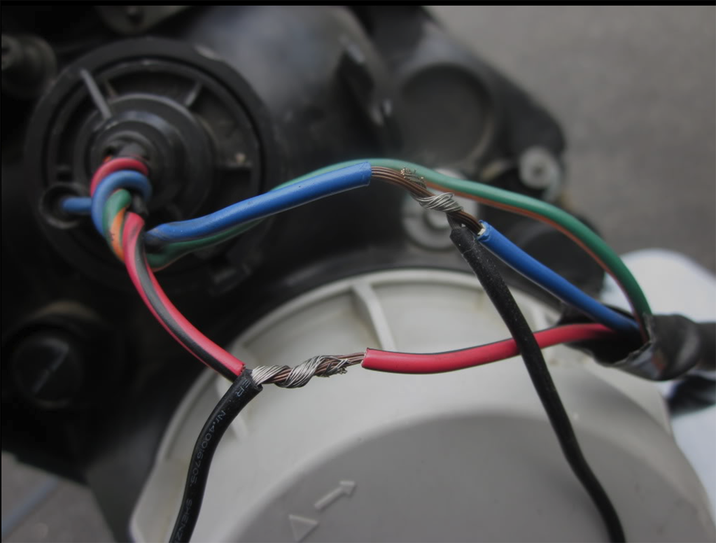
Look for Red/Black & Blue wires (DO NOT touch the green & orange wire)
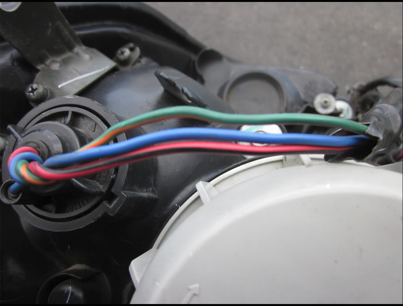 Then strip both Red/Black & Blue wires
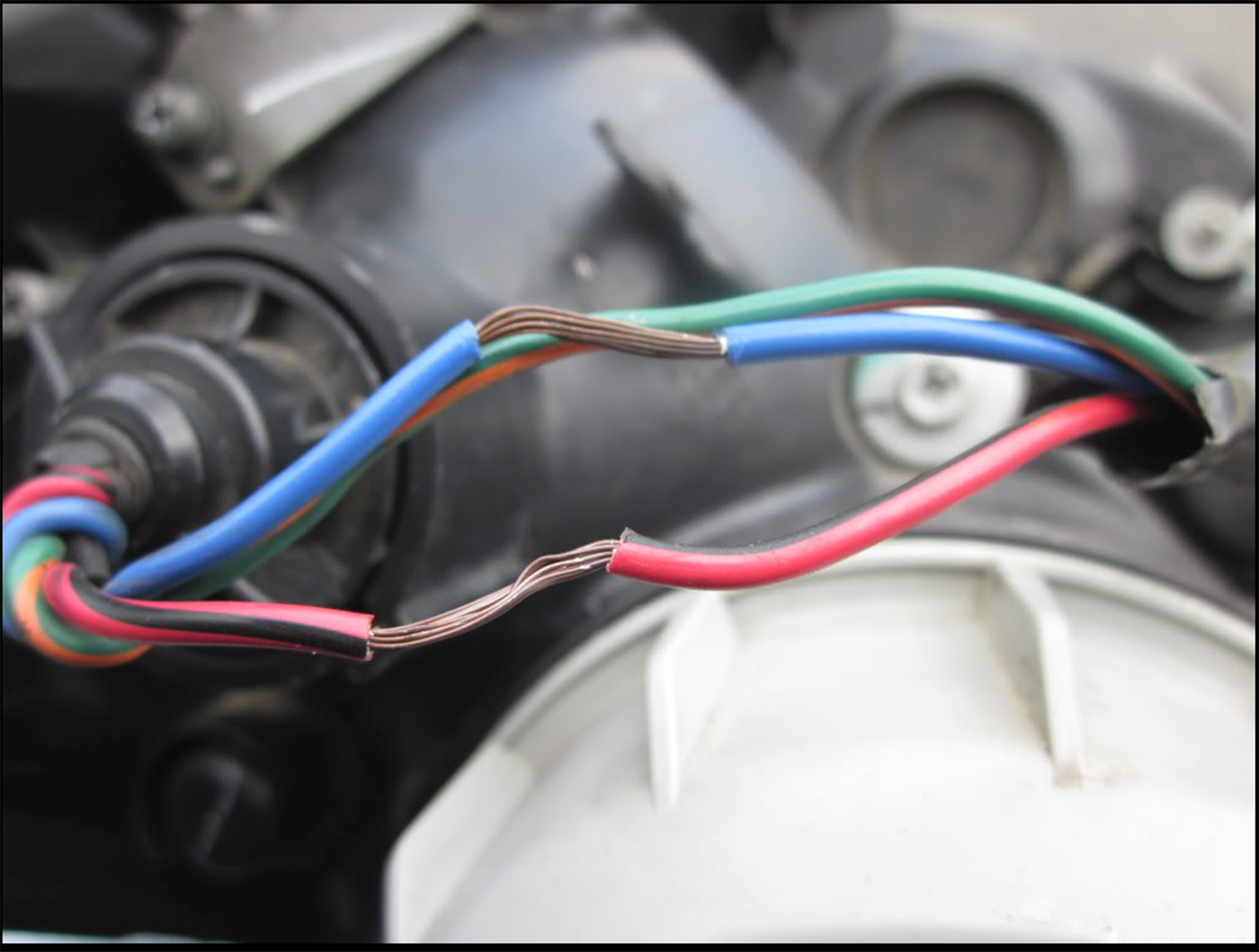 Strip the ends of the resistors:
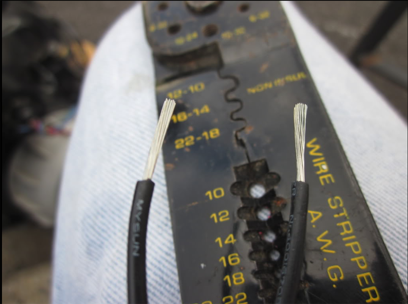 Wrap the ends of the resistors to the exposed wires on the headlights:
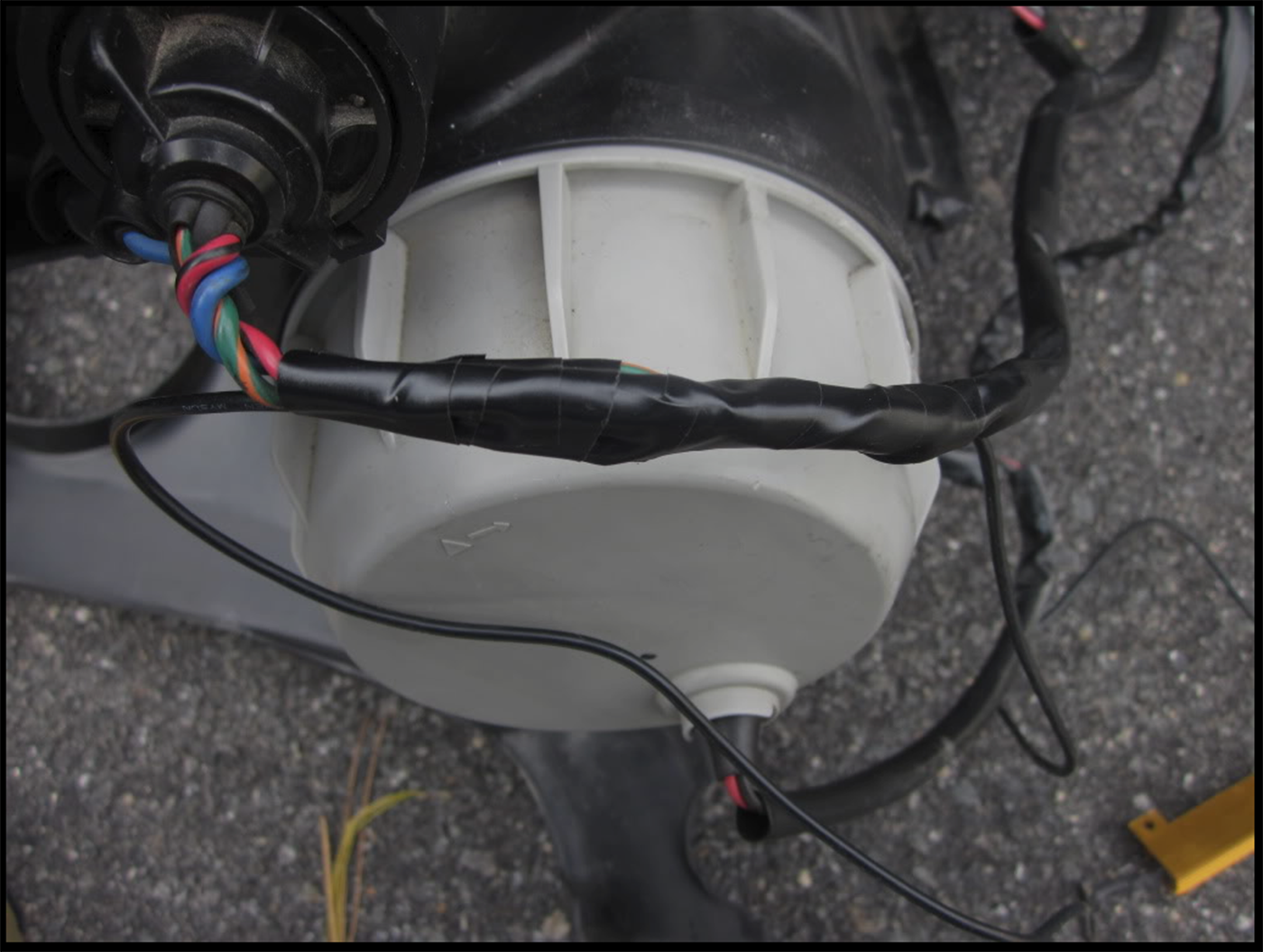
 I electrical taped the hell of the wires to make sure it secure, no wires exposed and no moisture:
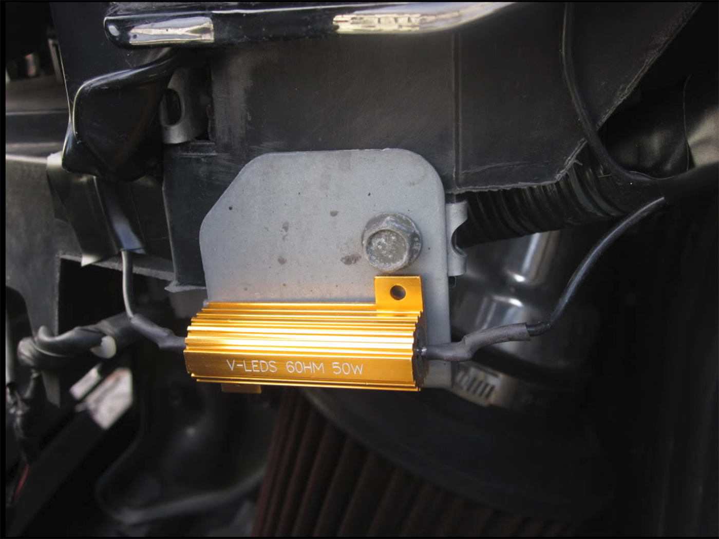
 Here is my resistor on the metal part of the bumper, the passenger side is just hanging.
![]()

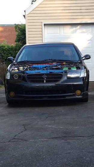
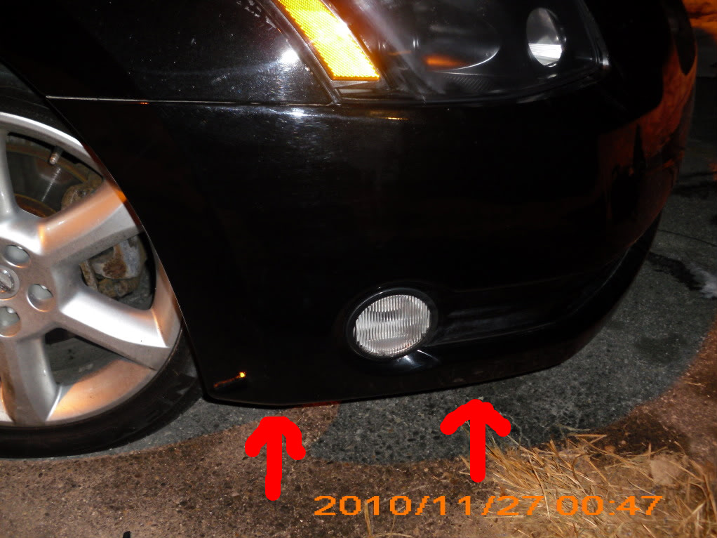
Member Credit: Elite Package
Hey guys i just recently painted the interior of my lights black to match my car. I just figured i’d write this post to help anyone out by giving “visual” instructions rather then “Text” instructions. So if you decide to tackle this project yourself like i did, hopefully you will gain enough confidence by the end of the thread to complete it successfully. Here we go!
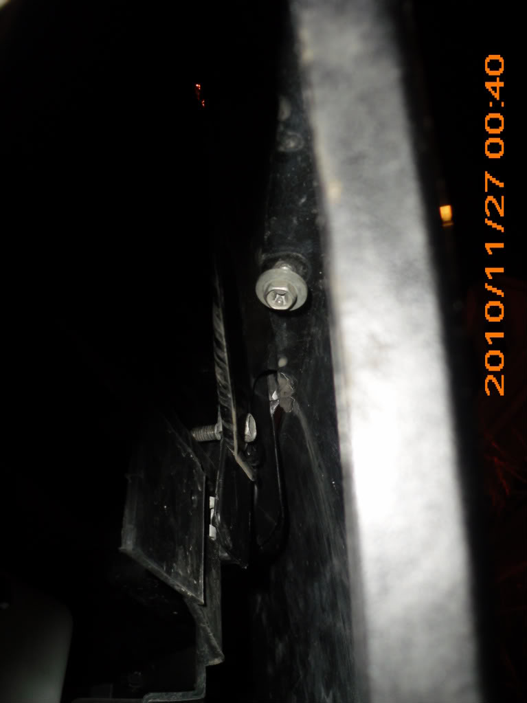
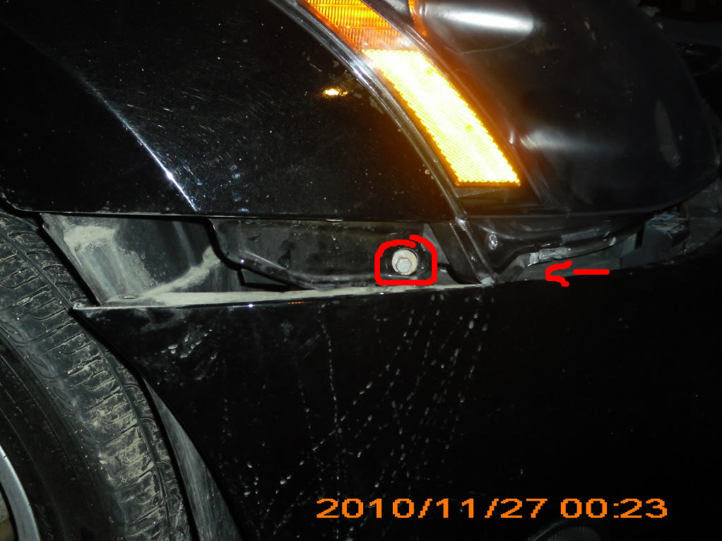
Start of by removing two phillips head screws underneath the bumper.
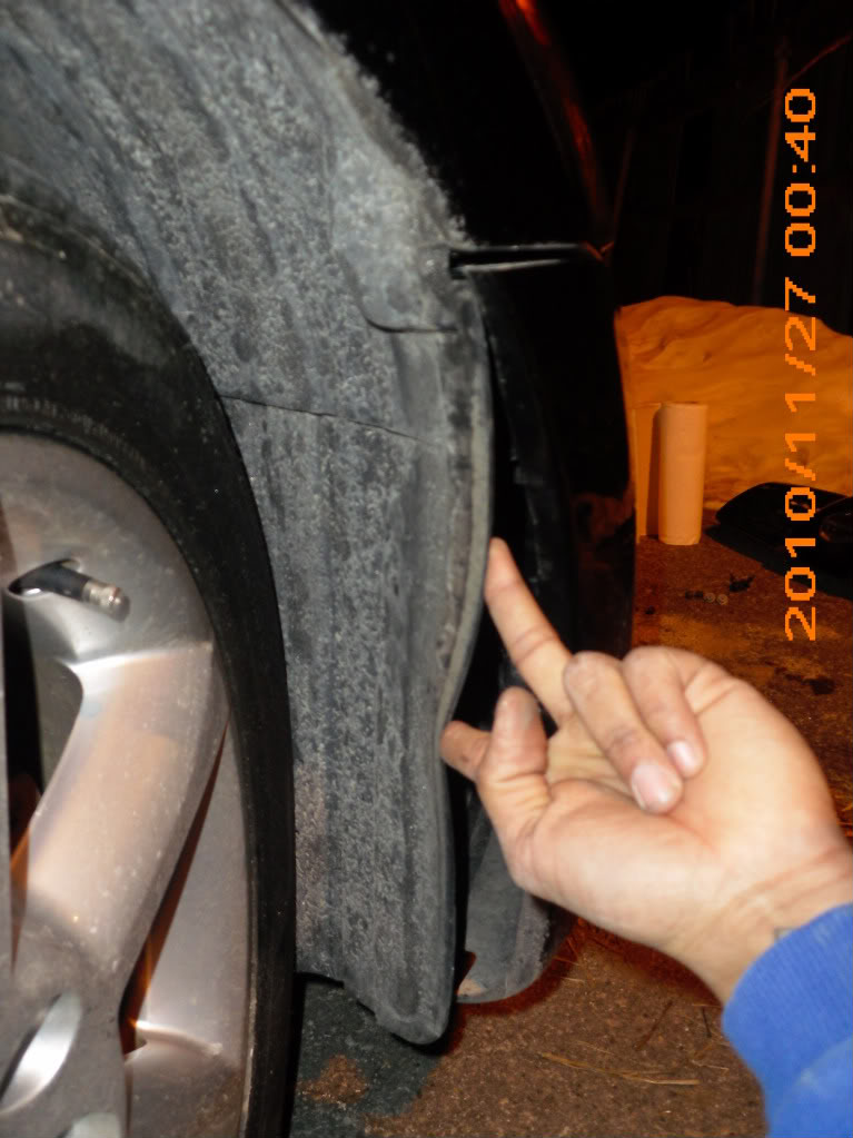
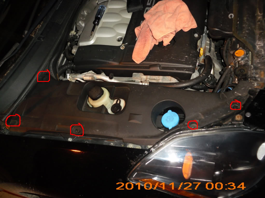
Next remove all plastic clips holding plastic cover underneath the engine.
Now, move plastic cover aside near the wheel to acess two vertical phillips head screws, remove those too.
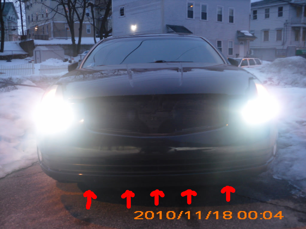
Next, remove all plastic clips holding down the grille.
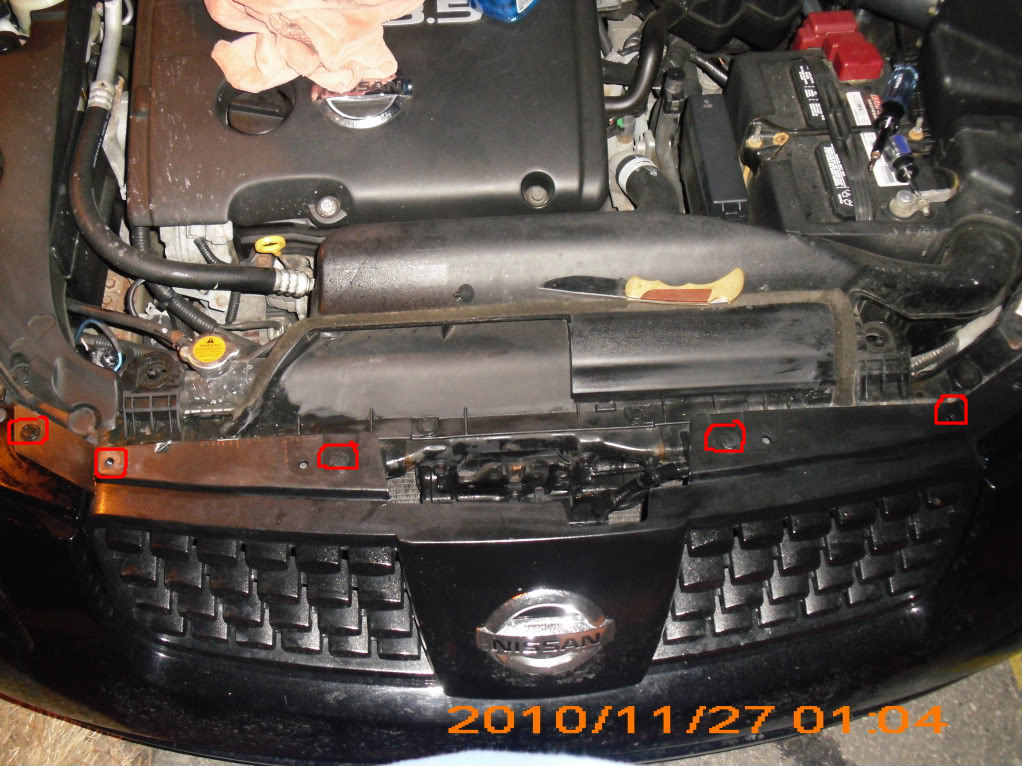
Also, remove all plastic clips holding down plastic cover over your windshield washer reservoir.
Finally, remove plastic clip holding down bumper cover to car body.
You should now be able to pull bumper off of the body.
– – – – –
Now you are ready to remove headlight.
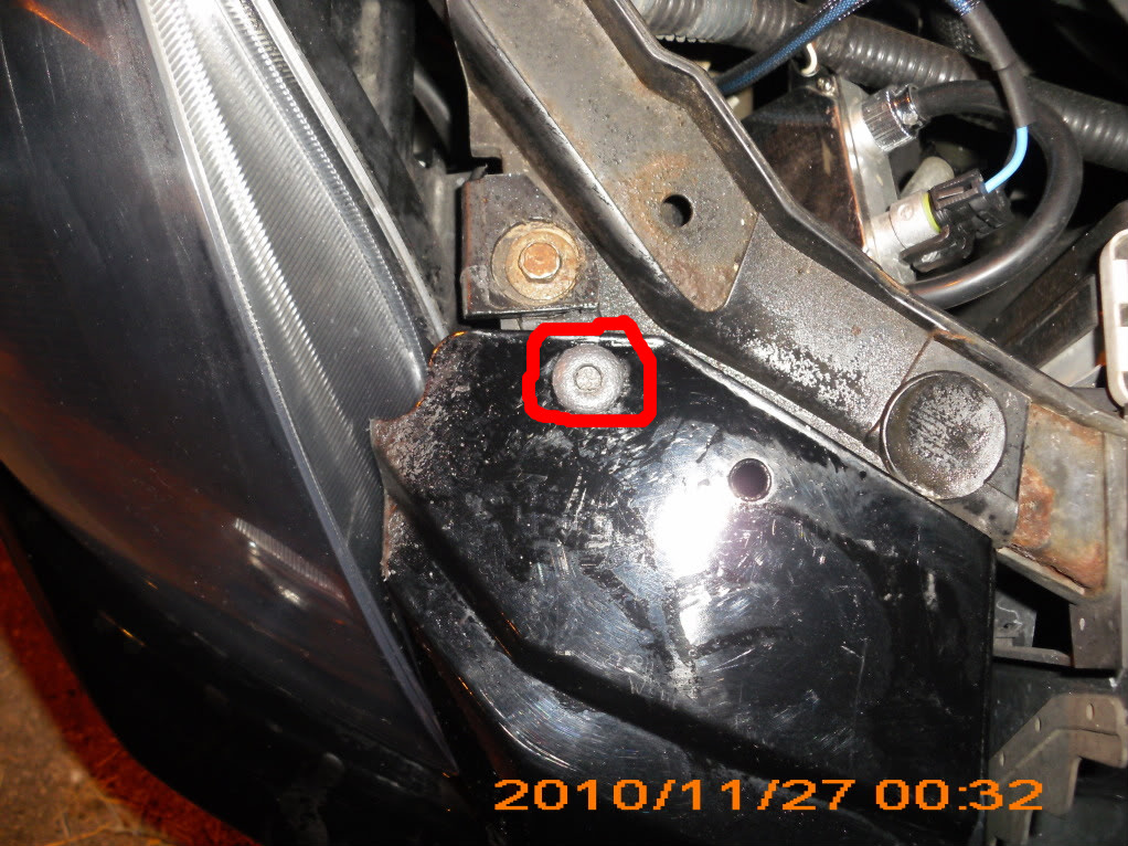
Start off by removing 4-5 hex head screws.
Now that the headlight is loosened from the body, disconnect your fog light wires.
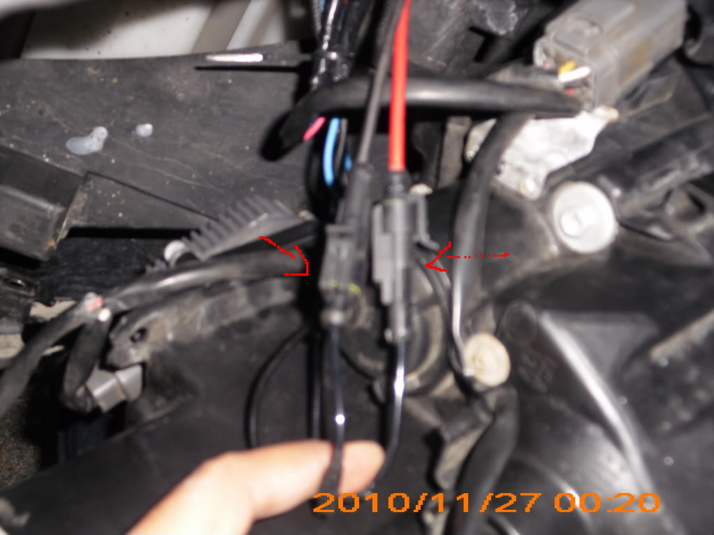
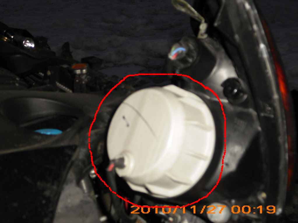
Untwist Cover
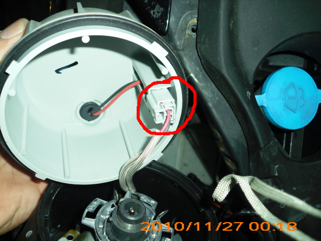
Disconnect small clip
Disconnect what i believe to be a factory ballast underneath the headlight.
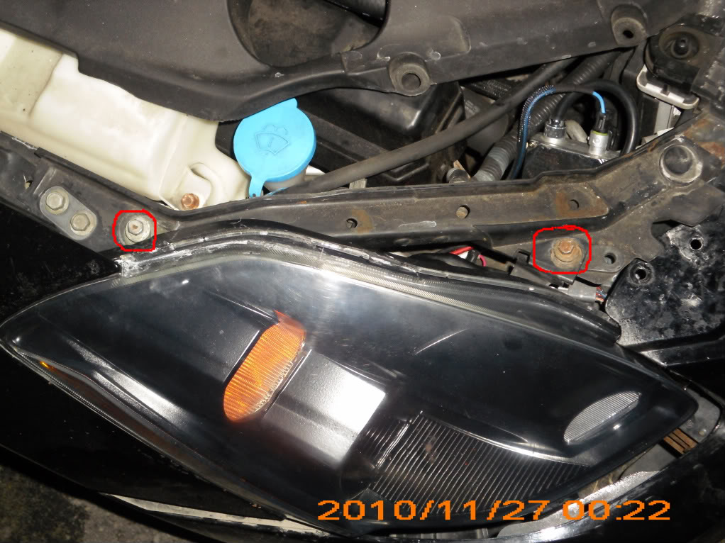
You will now need to remove 4 phillips head screws on the exterior portion of the headlight unit. (2 with a washer that hold wires in place 2 small ones without a washer that hold a bracket in place)
Once these are off you should be able to remove the headlight.
![]()


Member Credit: Marko Cvetic
This video is how to remove trim from 7th Gen 09-14 maxima’s.
![]()

Member Credit: Marko Cvetic
Tools: 10mm Socket Wrench
If you have a Stillen front lip and is painted make sure to lay a towel down so the lip doesn’t scratch. This will give you access to the headlights, foglights and grill
![]()

Member Credit: shift_ice
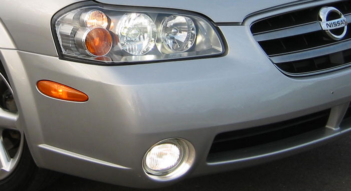
NOTE: The PIAA Super Plasma fog bulbs pictured below have since been discontinued. PIAA does make the Super Plasma GT-X but they are not as good a color match as the original Super Plasma. If you have pics of the GT-X bulbs that I can post here for comparison purposes or a’re aware of a better match please contact me.
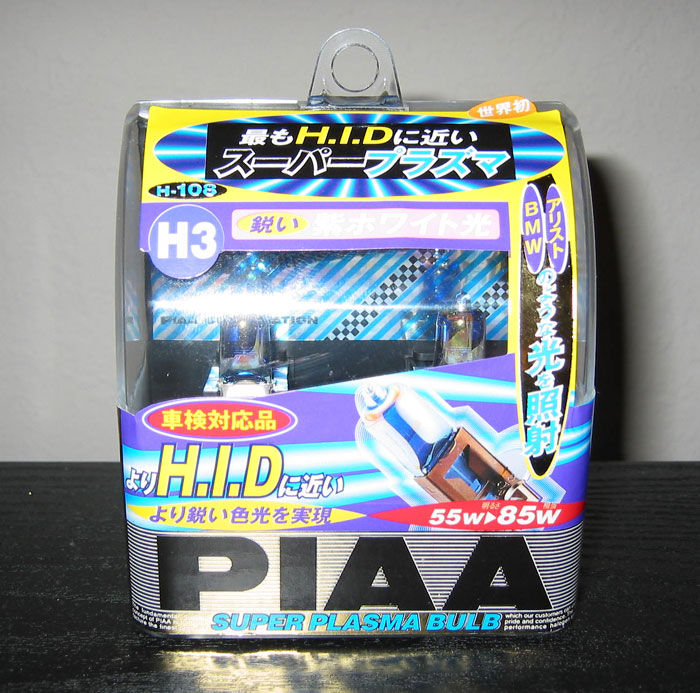
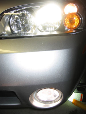
I installed PIAA 55W H3 Super Plasma Fog lights to match the factory HIDS. The fogs were purchased from Options Auto Salon. I’m really happy with the results. An excellent match with thefactory HIDS in my opinion. The install process is pretty simple:
1. Jack up car or put car on ramps for easy access.
2. Remove screw, bolt, and plastic pop tab from plastic guard underneath the fog light.
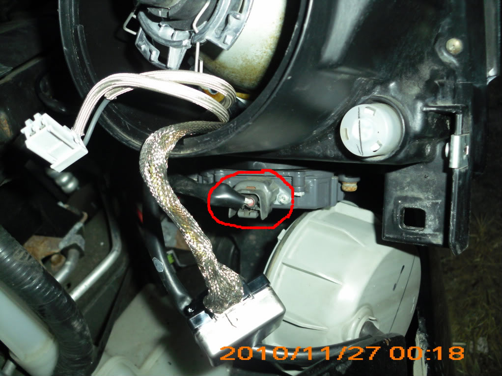
3. Unplug wiring harness using a small screwdriver to press the release tab.
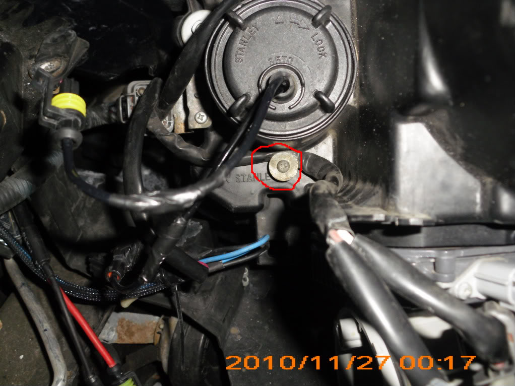
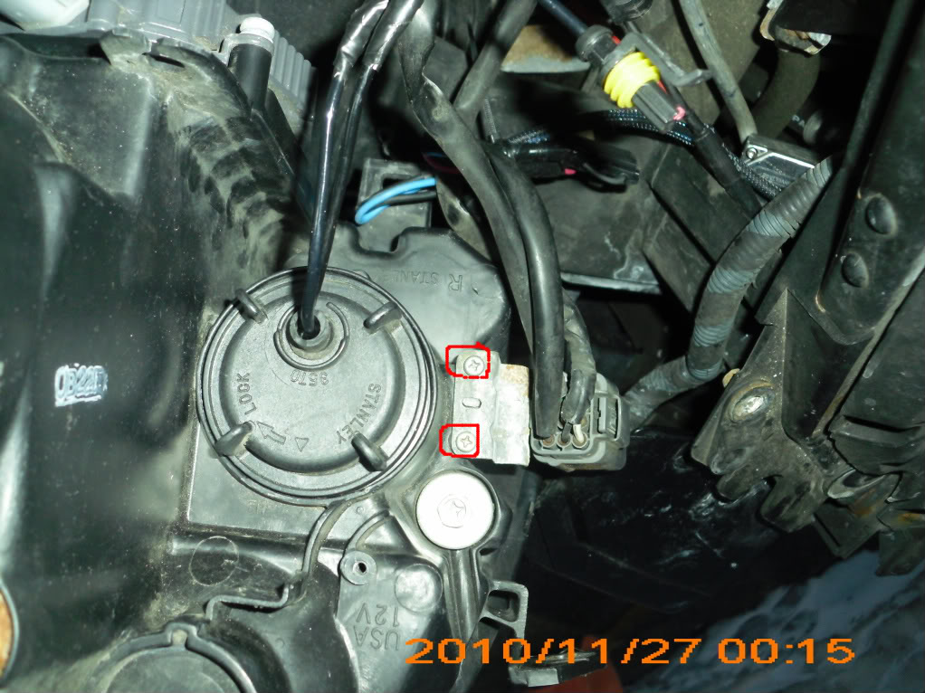
4. Remove 2 bolts from the back of the fog light housing.
5. Push on the back of the fog light to pop it out.
6. Remove the back of the housing by unscrewing counter-clockwise.
7. Remove screw holding metal pin down and disconnect the black bulb connector by wiggling connector back and forth while pulling.
8. Perform steps in reverse order taking care not to touch the bulb.
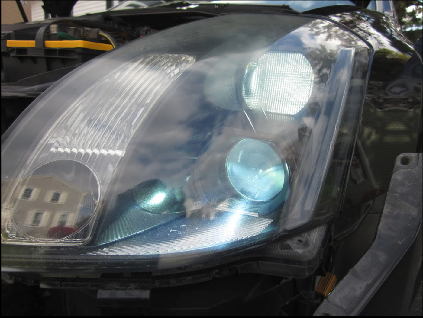
Before:
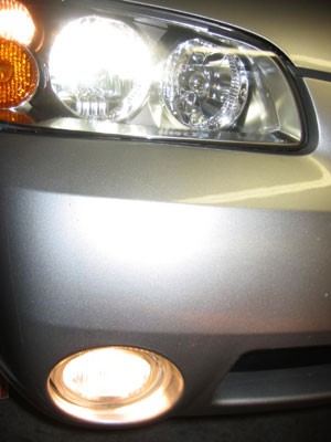
After:
![]()

Member Credit: Wildman04
I did the rear door first and the rear doors are a lot easier than the front doors are to do. The rear doors will take around 45 minutes to an hour and the front doors about two hours each, so probably allow a good day for the install. On a scale of 1 to 10 for a mod like this I would say it would be about a 4 for difficulty.
Do not post reply to this thread until I have all my posts uploaded, I have approximately 19 pictures with the details. I will have to post four times to get all information up.
Materials:
1. 4- 5mm 13,000mcd LED’s (purchased mine from eBay seller Ivehk for 3.99 plus 6.00 shipping for 50 pieces and resistors)
2. 3/32″ or 1/8″ polyolefin heat shrink tubing
3. 2 wires per door, approximately 2 1/2′ per wire per door
4. Solder
5. Electrical tape
6. 2 part epoxy glue
7. Butyl tape (get at glass store) or silicone sealant
Tools:
1. Ratchet, 10mm socket and extension
2. T-27 torx bit or 5/32″ allen wrench
3. Small flat blade screwdriver
Start with front doors and rear will be same process but easier. Pictures are all of the front door. With small screwdriver pry at marked locations below to remove cap at inside door handle, chrome strip on door panel starting at front and working to the back, window controls starting at rear edge. Lift window controls up, unplug connections and set aside all pieces.

Remove the three 10mm bolts at marked locations on door panel below. At the bottom of the door panel there is a lip, grab panel at bottom and give a quick jerk toward you and all door panel clips will release.

Now lift the door panel upward and off of door, lean panel to you to remove the latch cables behind the panel and disconnect all wiring to the door panel. Pull cables away from panel to unclip them and then separate from the handle. Set panel aside.

Before removing bolts to the inner panel, apply tape onto the outside of window over top of door and then to inside of window to make sure the window does not drop (do this at least at two locations). Remove all bolts marked below and the four nuts. Disconnect clips holding wiring to inner panel. Wiring running through the panel, push grommet through towards the door side and remove panel and set aside.

Look behind the outer door lock inside of door cavity and you will see a yellow clip on the lock rod, roll the clip towards the front of the door and it will unclip the rod from connection.

On the back edge of the door you will see a black plastic plug, pry it off of door and with the T-27 torx bit or the 5/32″ allen wrench remove the bolt under the plug. There are two plastic clips that will hold the bolt in keeping it from falling in the door cavity.

While pulling bolt tight to the clips, reach around to the outside of door and wiggle the small section of the door handle (with key hole on driver door) and remove from door.

Next, take the door handle and slide it towards the rear of the door until it stops and then pull outward and remove.

Drill a 1/4″ hole in handle where shown below. Glue LED into the hole you drilled and connect wiring to LED.

On one wire (preferably the ground side [large element in LED]) splice wire and install the 400-470 ohm resistor. Install heat shrink.

With the butyl tape or silicone seal the back side of the LED and wire connection to the LED.

Start installing the handle back into the door, inserting the wiring first. You will have to work with the rubber gasket behind the handle to get it to seat back right. With butyl tape or adhesive fasten the wiring to inside of door cavity leaving a small loop at the handle so working the handle does not put pressure over time on the LED connection.

Route wiring behind bracing in door cavity and finish adhering wiring to door skin leaving plenty of clearance for the window to raise and lower. Punch a small hole in the grommet and run wires through grommet.

Strip about a 3/8″ section off of each wire to the courtesy lights and check with your wiring from LED to get proper polarity(LED will only illuminate one way). Solder LED wiring to stripped sections and tape with electrical tape.

Kam wanted to see where all clips were on the door panel.

Finished product:


![]()