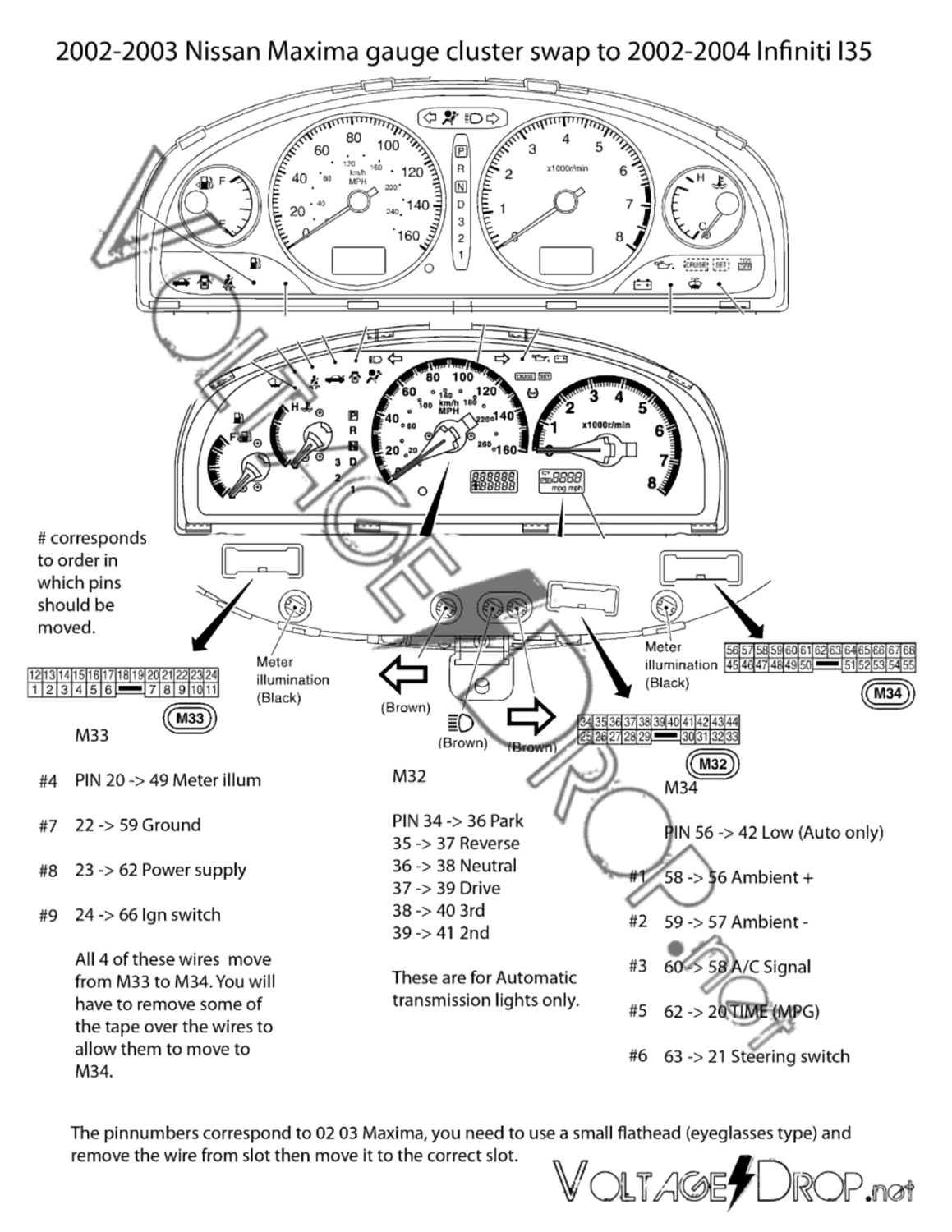
All you need to do is re-pin the wires. No need to extend them. It is best to start with the M34 Plug and then do the M32 Plug.
Re-pinning Instructions
Pinout Reference
#20 Red/Yellow —–Move To—— > #49
#22 Black —–Move To—— > #59
#23 Yellow w/ Red Strip Silver Dots—–Move To—— > #62
#24 Orange —–Move To—— > #66
#58 orange/Black —–Move To—— > #56
#59 Black –—-Move To—— > #57
#60 Blue —–Move To—— > #58
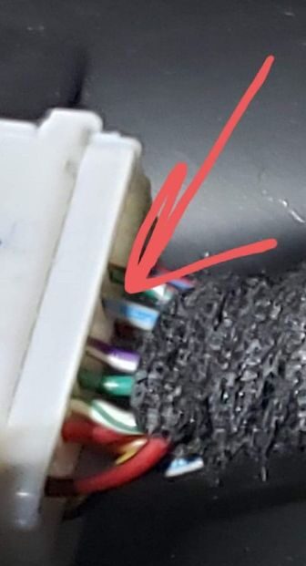
#62 Silverish w/ Blue —–Move To—— > #20 (See photo below)
#63 Green/ Brown —–Move To—— > #21
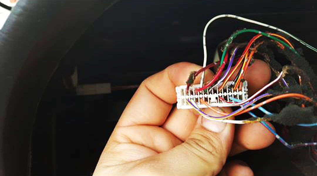
Backside of completed M34 Wiring
Backside of completed M32 Wiring
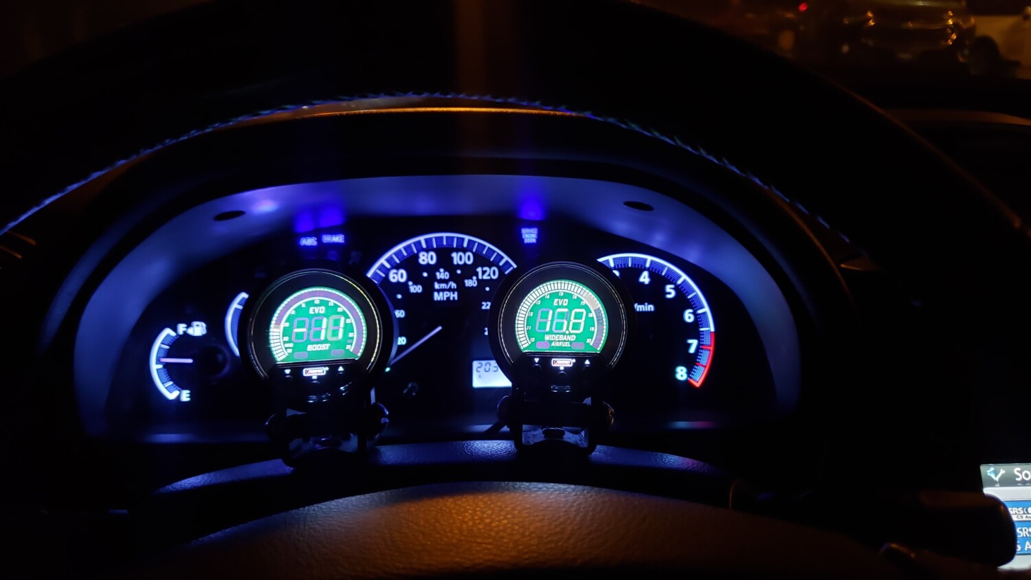
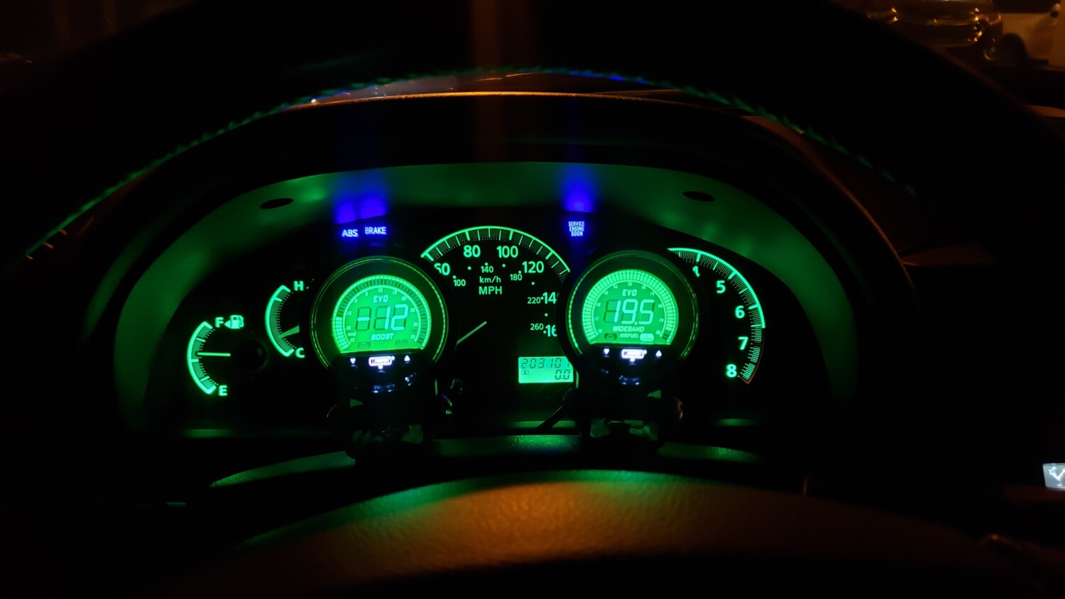
Comparison Wiring
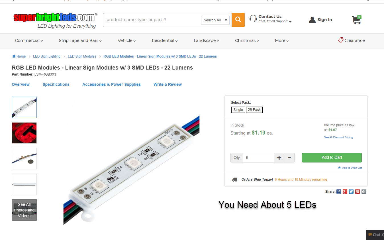
LED Color Swap
The Infiniti i35 has a single light source which makes it easy to swap to an LED strip. Below is what is commonly used since it allows you change the color as you want. I went with blue but good to have options. I tapped into an ACC power source for the lightening.
I would like to start by thanking JNCoRacer for his motivational pep talk. He was smart enough to know that I could do it, even though I didn’t think I could. Thanks man.
You will need various standard tools: screwdrivers (Phillips for screws & flat for prying), wire cutters and a ratchet, extensions (I found that my 24 inch was very useful), a U-joint, and a 10 & 12mm socket. I strongly recommend a 6 point socket for the 12mm.
You will need one special tool, a T50 Torx, 6 point security wrench. I didn’t have a security Torx but got lucky and was able to modify my standard T50.
Cliff notes version –
1 – Remove the glove box.
2 – Remove the radio/heater control cluster.
3 – Remove the speedometer cluster.
4 – Remove the dash.
Easy smeezy, right?
Let’s get started and find out.
Move the driver’s & passenger’s seats forward and remove the 2 screws that hold down the rear of the center console.
Move the driver’s & passenger’s seats all the way back.
Disconnect the battery. You will be messing with the passenger airbag and it is recommended to wait a half hour after disconnecting the battery.
Remove the glove box (6 Phillips head screws) and disconnect the 2 wires. You will also have to cut the zip tie that holds the wire harness to the glove box.
While you’re down here, remove the kick panel in the foot well. There is a plastic nut on the top front corner that you can most likely remove by hand. Then there is a snap along the top edge just before the panel curves to meet the door. Pull the panel towards the driver’s side to unsnap it.
Remove the radio and heater controls. Start by removing the trim plate around the transmission shift lever. If you have an auto trans, you need to move the shift lever out of park. I’m guessing that you’ll need to do the same with a standard trans. Pry up the 2 rear corners of the trim plate to pop the snaps free. Actually, pry on the sides by the corners, not the bottom edge. Lift up by hand to pop the forward snaps that are near the curve. When free, disconnect the wire for the cigarette lighter.
Remove the ash tray. Remove one screw at the top left corner. On the right side there are 2 snaps, one top and one bottom. Pry the ash tray straight back towards the rear. Did I mention that a 1 inch putty knife works better than a screwdriver for this? Disconnect the wire to the ash tray.
Now finish removing the center console. In the opening created by removing the ash tray, there are 2 screws in the corners where the center console meets the dash. Remove those screws, pull the parking brake handle up as far as you can, unsnap the boot around the parking brake handle and remove the center console by lifting up.
Remove the dash center vents. Pry up on the lower corners, the sides, not the bottom edge and pop the snaps free. There are 4 snaps across the top edge. Using moderate level swear words, free the top edge. While it is difficult to do, the vents need to come almost straight back with a little downward motion, not tilted up from the bottom. Once you have the vents free, disconnect the wires for the hazard flasher, clock and the rear window defroster switches.
Now you can remove the radio and heater controls. This is one unit held in by 4 screws, one in each corner, 2 screws down where the ashtray was and 2 on top above the heater controls. Have your transmission shift lever towards the rear of the car and lift out the radio/heater controls. Disconnect the wires from the radio and heater controls.
Remove the speedometer cluster. Since the goal is to remove the dash, this procedure will do things not needed if all you wanted to do is remove the speedometer cluster.
Start by dropping the steering column. Remove the lower dash trim panel that runs underneath the steering column. Remove the 2 screws in the bottom edge at the corners. There are 2 snaps on top edge, again at the corners. Pry the snaps free. *** Caution *** The chime that sounds when you open the door when you have the keys in the ignition is attached to the backside of this panel by the fuse panel. Disconnect this wire.
While you’re down here, remove the kick panel in the foot well, just like on the passenger side. Remove the metal plate that runs underneath the steering column. There is a 10mm bolt on each end. The plate will stay in place after you remove the bolts. Slide the plate towards you about a quarter inch and it’s off.
Now you can drop the steering column. Two 12mm nuts. Mine had Locktite on them and my 12 point socket was starting to strip the one nut, so I changed to a 6 point socket. The steering column is kind of heavy, so you are forewarned. I was concerned about the steering column hanging by itself, so I found a 10 inch length of 2 inch PVC pipe that I rested the steering wheel on.
Now for the speedometer cluster. There is a finishing bezel around the cluster that also has the cruise control on/off switch, the security led and the dash light dimmer switch. You have to disconnect the wires from these switches. You have 2 choices – before you remove the bezel or after. If you choose before, then you have to pry the switches out of their holes and then disconnect the wires. I chose the other option, after I had the bezel loose. This way I didn’t have to pop the switches out.
Start removing the bezel by removing 2 screws in the top curve of the bezel. Then there are 4 snaps along the bottom edge. Pry/pull them free. If you hadn’t done so earlier, disconnect the wires from the switches.
Finally, the speedometer cluster itself. 3 screws, 1 at the top and 2 along the bottom. There are 3 connectors on the back of the speedometer cluster that need to be disconnected. I would suggest you get something soft to lay the cluster face down on while you disconnect the wires so you don’t scratch the face plastic. It costs about $35. You will also have to cut a zip tie that holds the wire harness onto the back of the cluster.
Now disconnect the wires from the side view mirror switch. Either pop the switch out or reach in from behind the dash.
The final phase, remove the dash. There are 5 10mm nuts, 2 Torx head security bolts and a pair of screws to go.
Remove the trim pieces from the windshield pillars by grabbing the trim at the top edge and pulling the snap free. Then lift it off.
Pry off the defroster vent grill plates. There are 4 snaps spaced along the back edge. Pry the back edge of the grill up.
When the grill is removed, you can see a 10mm bolt at the end closest to the outside of the car. Remove this bolt. This is where my 24 inch extension was useful.
In the bottom left and right corners of the dash is a 10mm nut that was revealed when you removed the kick panels. Remove these 2 nuts.
In the opening where the speedometer is a 10mm nut.
In the opening where the radio was there is a screw.
In the opening where the glove box was is a screw.
OK, last 2 fasteners and one wire harness connector. Looking in the glove box opening at the top, you will see a yellow wire harness connector. This is for the passenger air bag. It looks like you could pull either end out, but you have to pull the right side out to disconnect it.
Now for the Torx bolts. Look up through the glove box opening and you will see 6 Torx head bolts. You only need to remove the 2 that are by themselves, not the pairs.
Once you have these 2 Torx bolts out, the dash is free and ready for removal. I did it by my self, but if you can get a helper, it is no doubt a lot easier. You have to pivot out the bottom edge a little bit and then pull back and up. There are guide pins built into the top front edge of the dash that require you to pull the entire dash back evenly. Because of the airbag, the right side has probably 75% of the weight.
For what ever it’s worth (in the category of useless trivia), I weighed the dash on my bathroom scale. It was 25.5 pounds. Most of that is the airbag.
Following up from 95maxrider’s awesome door lock actuator thread. So My ’99 developed an issue wherein all of the locks would only lock / unlock halfway. The problem got worse with the cold weather, to the point where the rear passenger side door wouldn’t unlock at all. I got tired of reaching around to manually lock all of the doors before exiting the car, so I decided to do something about it.
I figured the actuators were failing – no problem, right? I’ll just grab some from RockAuto. Well, I soon found out that the prices for our actuators have become ridiculous. The cheapest prices for the rears were about $150 each, and the fronts were about $85 each, while the 5th gen actuators are about $10-$15 each. I didn’t want to take the chance on a used JY / ebay part, so I began to look at other options. I found a set of four universal actuators on amazon for $13 shipped, and I took a chance. What’s the worst that can happen, right? if they didn’t work well, I was only out $13. Link to the actuators I purchased is here: Amazon Amazon
They arrived a few days ago and I began the project. I started with the rear d/side door. The universal actuators came with no instructions of any kind. Thankfully, the install for these things is fairly straightforward, and I’ll do my best to recap what I did. If you can install a radio / amp, you can definitely do this.
1) First, you need to remove the rear door panel. If you’ve never done this before, here is a video tutorial, thanks to pmohr:
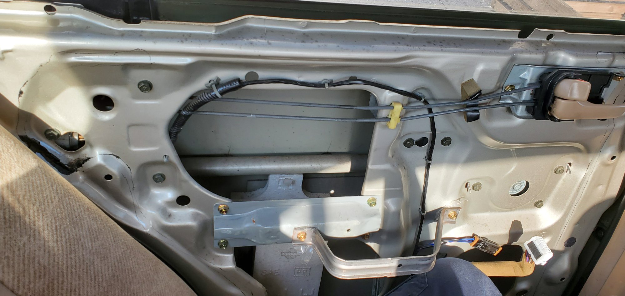
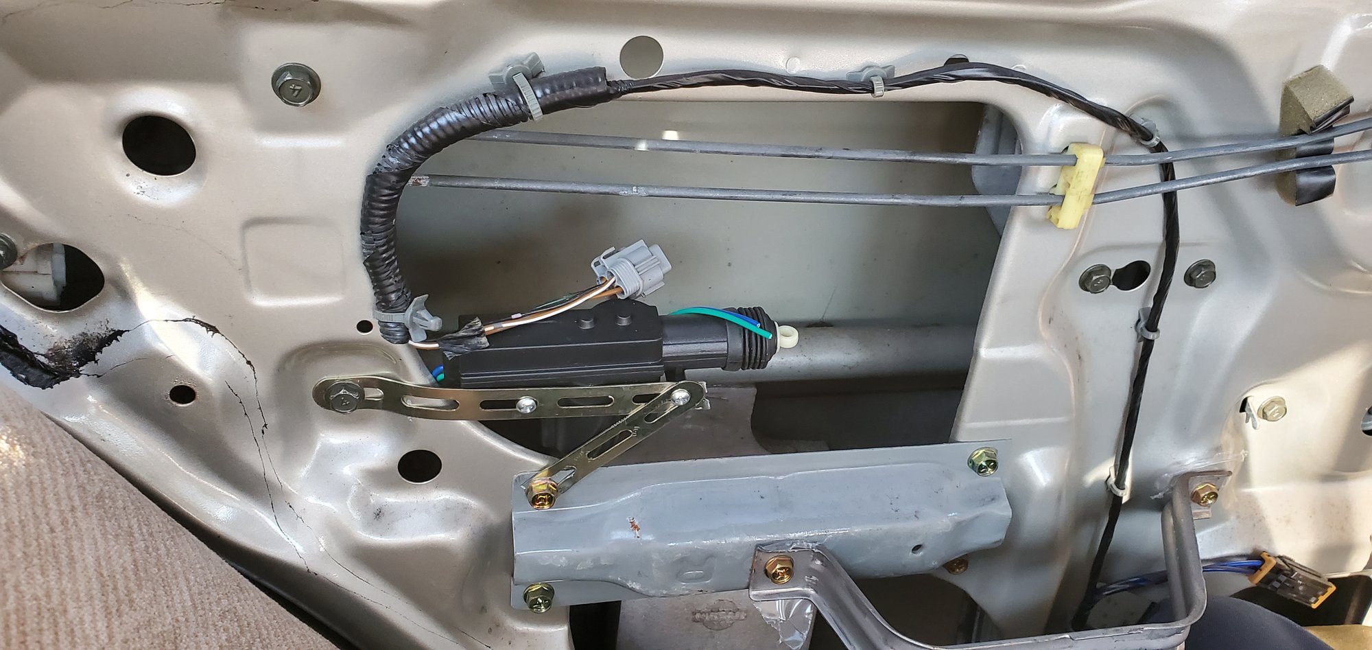
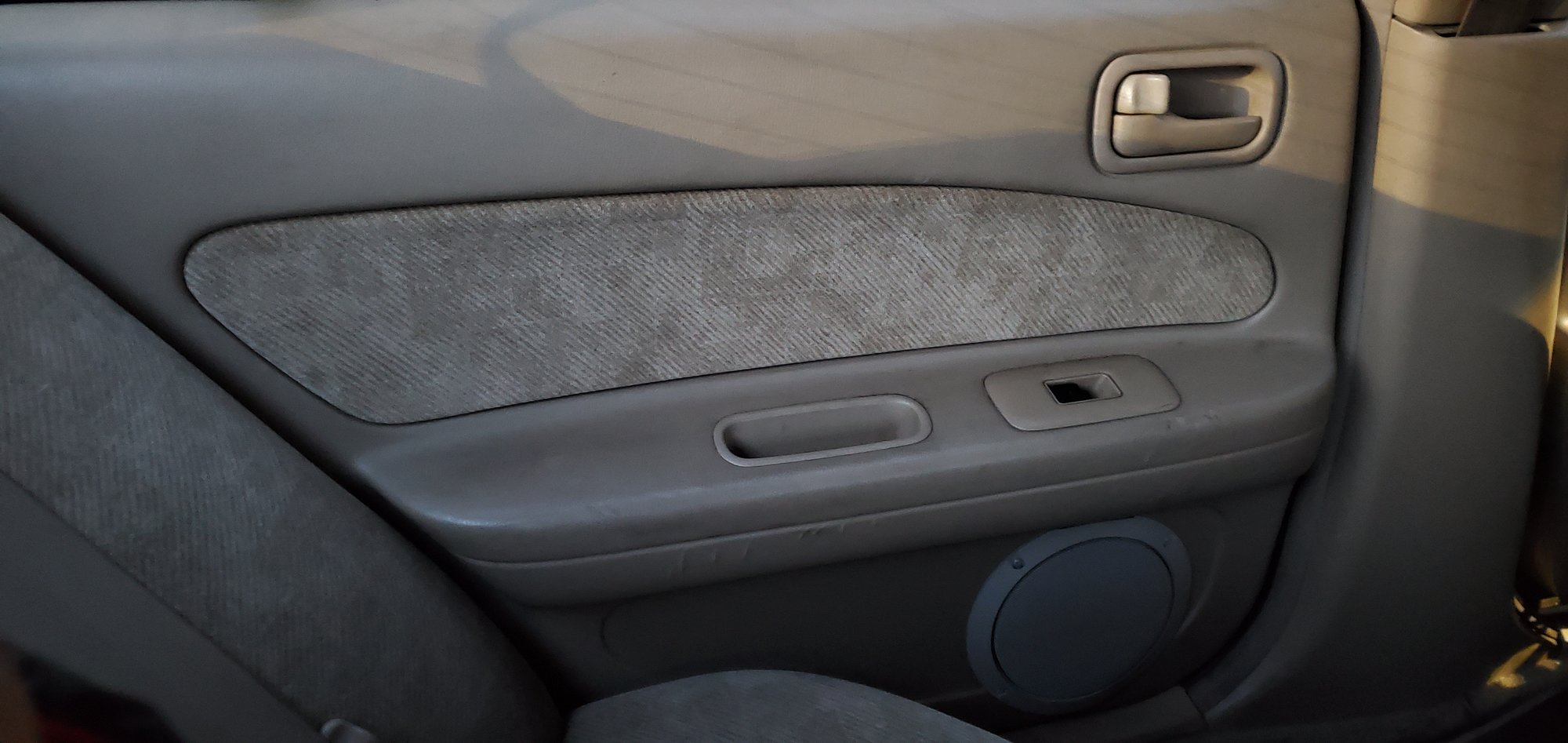
Once you have the panel off, you’ll be looking at this (I removed the factory plastic moisture barrier):
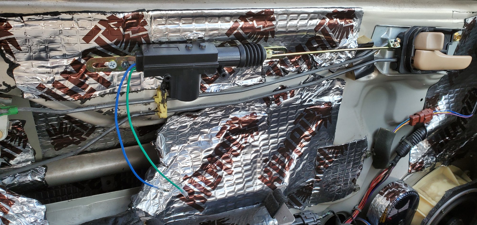
2) The actuator is hidden behind the door frame. You can see its harness through the hole near the seat. I removed the harness by pushing a flathead screwdriver through the hole, to release the clip. Then I used a second screwdriver to pry the harness out while pressing on the clip with the 1st screwdriver. Once I had the harness out, I bolted the actuator into this spot. To get this to work, I had to break the mounting bracket that it came with. This is a great spot for the actuator, because you don’t have to drill any new holes in the door frame. You can attach it to the existing bolts in a V orientation:
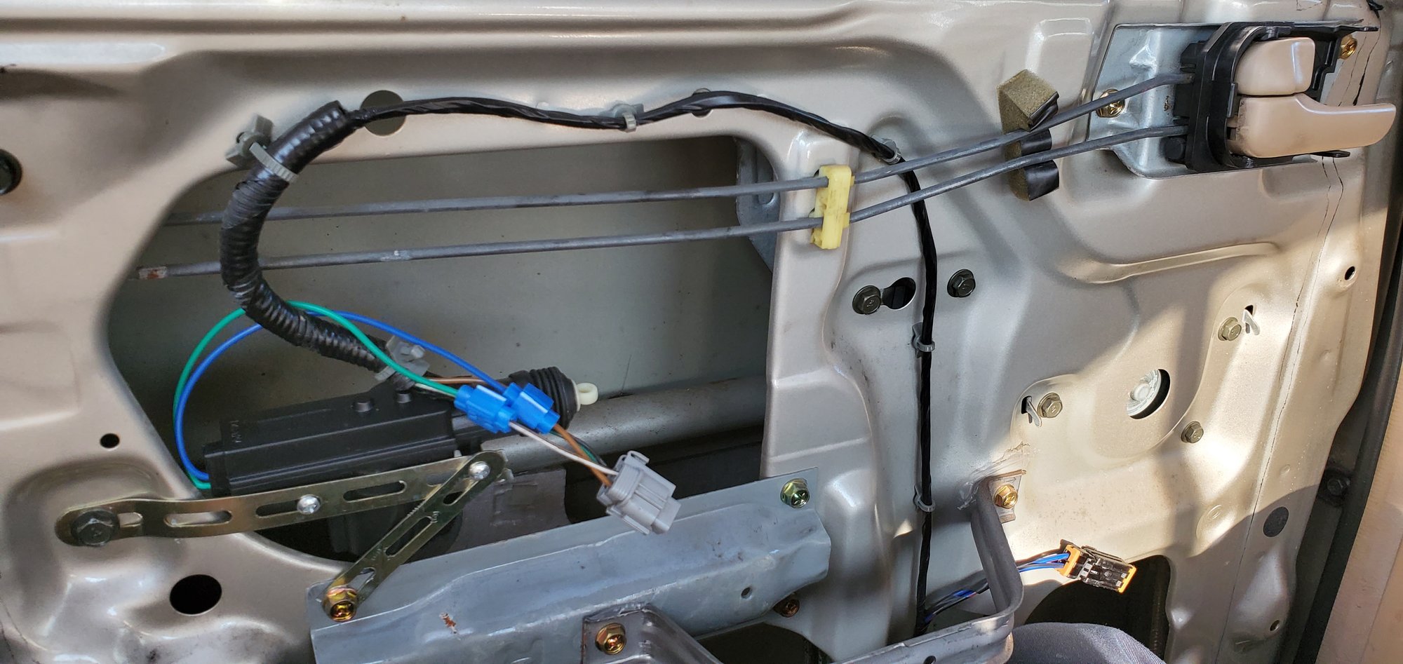
4) On the factory harness, the wires that you’ll want to tap into are the brown / white and solid brown. Connect the brown/white to green, and the solid brown to the blue wire of your universal actuator. The blue wiretaps work great for this
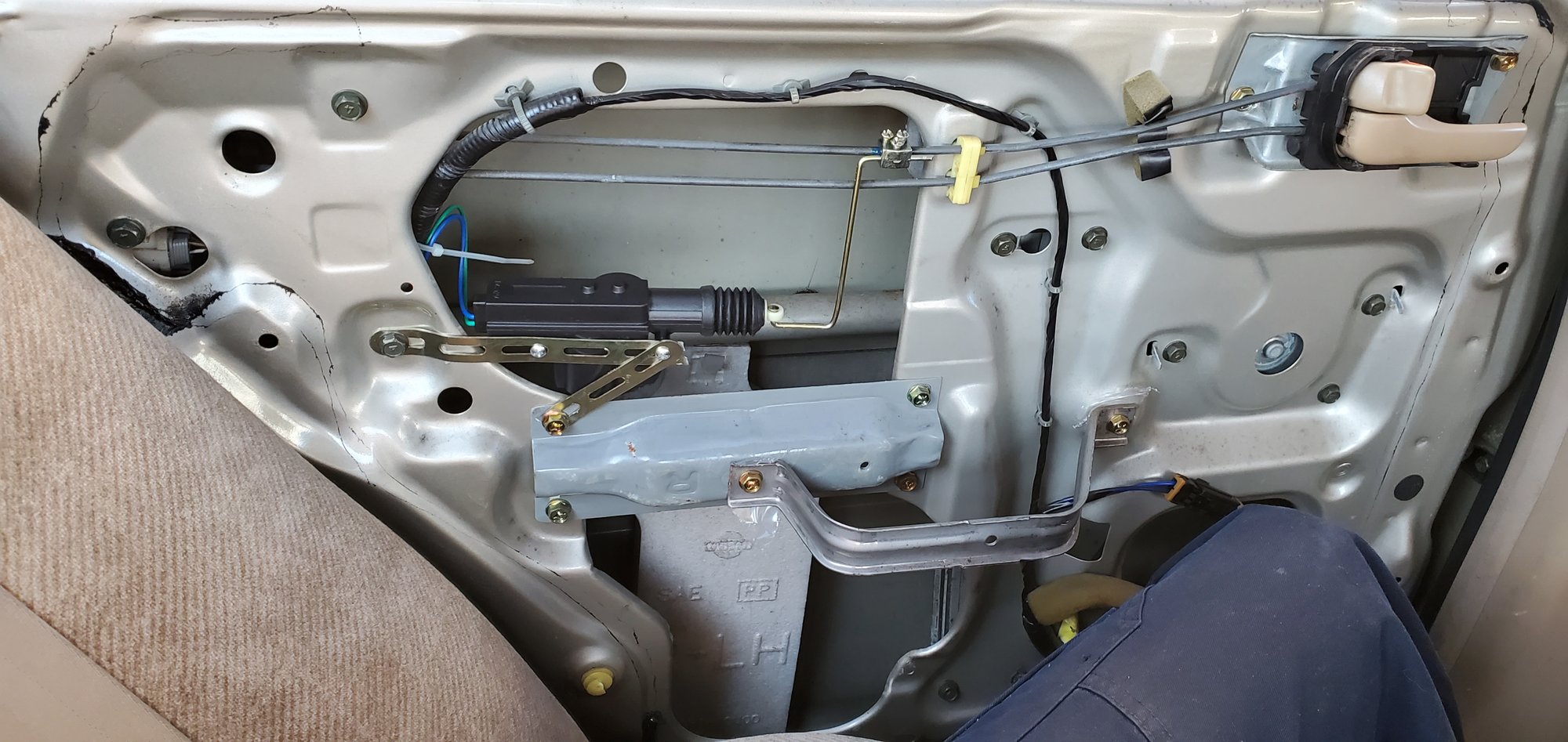
5) Once the wires were tapped, I plugged the harness back into the OEM actuator. This was not even necessary, because the universal actuators are more than sufficient to push / pull the rods, but I insulated the taps with electrical tape and reconnected it anyway. Once your wiring is done, you’ll need to connect the universal rod to the factory rod. I bent it into this shape, fed it through the actuator, and connected it to the factory rod with the supplied clamp and screws. **IMPORTANT** – before you bolt the new rod in, make sure that the orientation is correct – if the lock is OPEN, you want the new actuator to be EXTENDED. if the lock is closed, you want the actuator to be fully retracted. I added some blue Loctite to the clamp threads as well, in the event that the screws somehow loosen up over time.
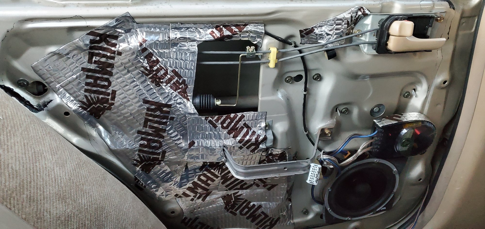
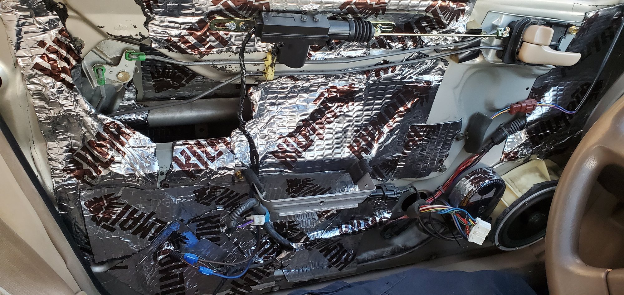
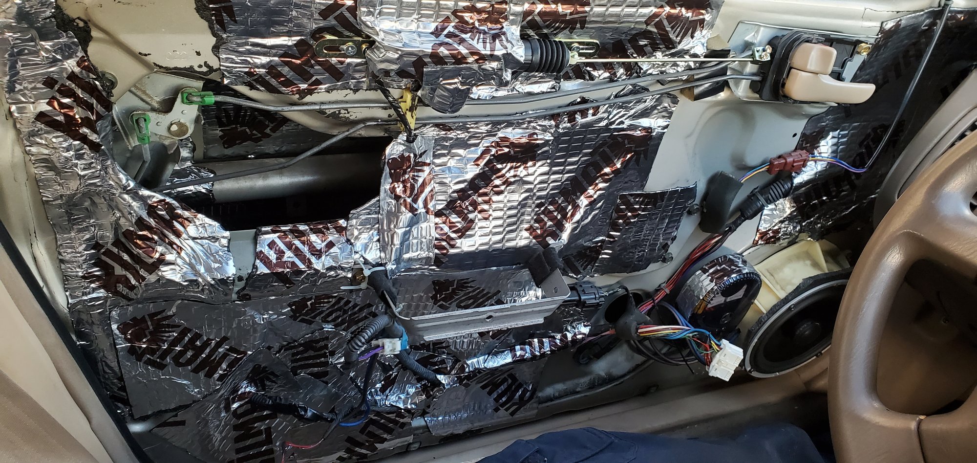
7) While I had the panel off, I decided to add some speakers to the rear doors, to give my audio some rear fill. I had some coaxials that I had taken out of my previous car, so I decided to throw them in. Slipped a 6.5″ Boom Mat baffle into the hole there to create a tighter seal and also to protect the speaker. I cut out the rear of the baffle to allow for airflow. Bolted the speaker up, wired up the crossover, and fed the input wire out of the existing door grommet, and down through the B pillar into the car. adding the rear speakers made a HUGE difference in sound! The rear speaker doesn’t interfere with the operation of the window either, since our windows only go down halfway anyway.
8) I re attached the door panel, after using a 6″ hole saw to create an opening for the sound to come through. I covered it with a grille that I spray painted. The paint dried lighter than the representation on the cap, but I was more concerned about function over form… I didn’t really care about putting a hole in the panel, because the panel was already in rough shape anyway…
9) The lock now works perfectly! Video attached:
So that was the rear. Today, I completed the front. Similar process. Here is what I did for the driver’s side: 1) Remove the front door panel (thanks again pmohr)
2) I chose this spot to mount the actuator. Before I screwed it in, I made sure that the panel would clip on properly without being obstructed by the actuator. It did, so there it went. Be sure to measure the new rod before you bolt it in place, because I had to clip off about 2 to 3″ of it for this application. Once I had the correct length, I fed the rod through the actuator, pushed the rod through the clamp, and then I snapped the clamp onto the factory rod. Applied some loctite and screwed it down. Of course, I managed to lose one of the screws. There are supposed to be two screws securing the new clamp to the factory rod, and one screw securing the clamp to the new rod. It held fine with one screw, so I proceeded.
3) I already had some sound dampening material on my front doors, so I had to peel some of it back to access the wiring harness for the front actuator. It runs along the bottom of the door. I pulled it inside of my kilmat, and stripped away some of the plastic conduit to expose the wires. Same deal here as the rear, you want the brown / white and solid brown wires. Since the new actuator is at the top, and the wiring is at the bottom, I had to extend the wires. I crimped on some 14ga cable, wrapped it up, and ran it down to the factory harness. Used the blue wire taps again, wiring done!
4) Tested the new actuator, works perfectly! The lock snaps open and closed as if it were brand new. Video attached:
https://vimeo.com/user104171777
5) Wrapped everything up with tape, put some kilmat over the new actuator to help protect it (probably not necessary, but didn’t hurt anything).
6) Once I confirmed everything was working correctly, I put the door panel back on. It snapped right back into place. No resistance or snags of any kind. Well guys, the verdict is that these actuators are a definite hit for $13. I mean, that comes out to about $3.25 per door. So if anyone out there is in a similar position, I definitely recommend giving this a shot if you’d rather not drop about $500 on replacement bolt-on actuators. I hope that this thread can be helpful to some. Hopefully I didn’t leave anything out. If anyone has any questions, feel free to ask.
I know some of you were interested in wiring your Map light(s) to illuminate when the Dome turned on, and some of you already have. Either way, I thought I’d let you know what I’ve figured out.
The best way I see to do it properly:
Tap into the ground wire (Dome light to SECU [Smart Entrance Control Unit]) Terminal #31 between the SECU and Dome light and install a relay there. I’d do this AT the SECU, most room to work. You want to hook this into the trigger side of the relay.
Here is the location of the SECU:
Then run a 2 Wire cord (preferrably one line with a tracer) from there, up to the Map light (up the Left A pillar and over).
The switch Wiring in the Map light seems to differ. I found 2 set ups.
1. On my car it’s a Single Map light, and it is wired with power to one side of the switch, then when you press the switch power flows through the light and to ground. (standard switch set-up)
2. It appears on some models, with 2 map lights, power is supplied to the light bulbs, and the switches are installed on the ground side (makes the ground connection).
Hooking up the wiring for the first one is easier, all you have to do is attatch (solder) one wire to the bulb side (see wiring diagram), and one wire to the live (+) side. Then down at your relay, connect the wire you connected to live (+) to the relay, and connect the wire you connected to the bulb side on the other end.
Here is my amazing Wiring diagram of the new set-up:
The second way, you have to change the switch type for the Map light.
+ must be triggered by the push switch (before the bulb). That change is pretty straight forward, nothing real complicated, if there are any of you that don’t understand how to do it, post a good picture of your Map lights (unit removed, picture of the back side wiring) and I’ll show you what to do.
So with this set up, we have No diodes, everything operates normally, no extra bulbs. Only thing that changes, is the Map light comes on when the dome light illuminates
I thought I’d let you all know how to do it, in case you were scratching your heads on it, I know some of you have done different things to get this function, some pretty creative, some a little chinsy, anyways…
I know initially you’d just think, jump a wire from the Dome light, and if you don’t have a sunroof, I’d consider it.
I have a sunroof though so this is the best way I can think of (to have it operate properly without installing extra lights and non-sense)
Pull out the Map Light, and unscrew the Sunglass holder. Also pop the cover off the Left A-Pillar. This pic shows all 3 removed, and my wire fish run through already:
Now run your wire fish from the corner of the headliner on the A-Pillar side into the sunglass holder hole. You can probably use a coat hanger or just push the wire through, it’s pretty easy going, everything is framed in the corner.
Hook your 2wire cord onto the wire fish, and feed it through toward the A-Pillar
Now you want to run the wire fish from the fuse panel area (by pedals) up to the A-Pillar base (top of dash). Hook up again and pull through. This pic is with the wire already run.
Now the easy part Locate your SECU, remove the harness connectors (3) and move the wiring so you can work with it easier. And Use my Guide in the OP to locate the proper terminal. It`s a process of elimination to find the harness you want, mine was the middle one, I would assume all years will be the same. I know the terminal designation is the same.
Here`s the wire we want.
Now cut it.
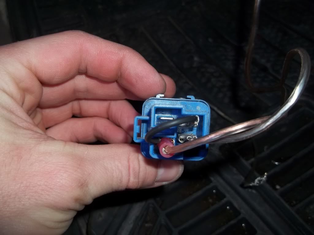
That`s right, only genuine Nissan Parts Any standard SPST relay will work.
I kind of cheated with this wiring cause I ran out of female spades and I wanted to get it done. So the Constant power wire (has red insulation on it in pic) needs to be doubled up (split wire, add 2 female spade connectors). You`ll see what I did in the second pic
Above is everything hooked up except the Ground (terminal wire you cut). I Forgot a pic of the Crimp on the Terminal wire. You just want to join them together into a Female spade connector, you can see it pretty clearly in the pic below (red wire). Please ignore the crudity of the wiring install, it’s temporary, I’ll be installing a SPDT Relay to run my LED handle lighting, at that point I’ll be re-doing the wiring and mounting the Relay
Now, wire in that MAP Light. Hook up the Constant Positive wire (with tracer) to the Constant Positive connection at the Switch
And then hook up the intermittent Positive wire (no tracer) to the output side of the switch (to bulb). I didn`t post a pic of this cause I couldn`t get a good enough picture of it. Plug in the SECU harnesses, the MAP light and DOME light should come on (if you hooked everything up correctly, and the door is open)
If everything works, install all components and make sure all wiring, etc is secure. And enjoy your new modifcation every time you open your door or unlock your car!
Lights off:
Unlock button pressed, lights illuminate:
Door opened:
Just so you know, you can`t shut off your MAP light while the door is open, I don`t know why you`d want to though. It still functions normally when the doors are closed. Another great thing about this mod is, you can shut off the Dome light and have only the MAP light illuminate if you want to (kids in the back sleeping, but you still need light when the door opens) Enjoy!
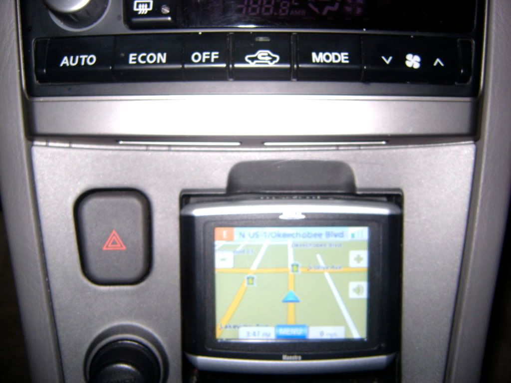
I have has multiple emails on the Navi install on my 2003 maxima via taking out the ashtray. The Navigation Model is the Magellan Maestro. It matches the TE edition perfect as you can see it is also silver and black just like most interiors in the SE family.
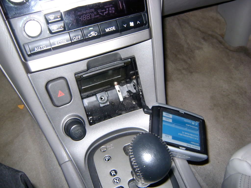
All I did was run the power from the rear socket spliced it in, then cut a small hole in the side of the ashtray holding container. Taking out the ashtray was simple you just unscrew the center screw in the middle of the ashtray, then pop the whole shifter cover off (holds ashtray) and there will be 4 screws that hold it in place, take those out and the ashtray box will come off with ease.
There are tabs on the side of the ashtray that will allow you to take the slider off with ease, then just go ahead and cut the side of the case with a warm knife, and slide the power connector through.
High Beam
Red connector is connected to the 2K harness green wire as shown in the next photo
The blue connector is wired to the blue wire that I put there, it is the power wire from the 2K harness, it powers both the high beam and the HID.
Turn Signal
The right side wire from the Grey plug on headlight, is for the running light, and connects to the brown/red wire in the turn signal plug.
The right side wire of the brown turn signal plug connects to the ground (black wire) on the car turn signal plug, and the left side wire of the brown turn signal plug connects to the green power wire on the car plug.
The middle wire coming out of the the center grey plug is connected to a chassis ground, and the picture got cut off, so you cannot see the left wire of the grey plug is connected to the same blue power wire that the high beam light is connected to here:
The right side wire from the Grey plug on headlight, is for the running light, and connects to the brown/red wire in the turn signal plug.
The right side wire of the brown turn signal plug connects to the ground (black wire) on the car turn signal plug, and the left side wire of the brown turn signal plug connects to the green power wire on the car plug.