So everyone doing the conversion isn’t sure why the park lights don’t work. Some suggest cutting and splicing to get them to work, but that’s not the right way. It’s as simple as removing one pin from the headlight harness and inserting it into a different location. My friend MaxPrime came through, and I showed him how simple it is (for me, anyway).
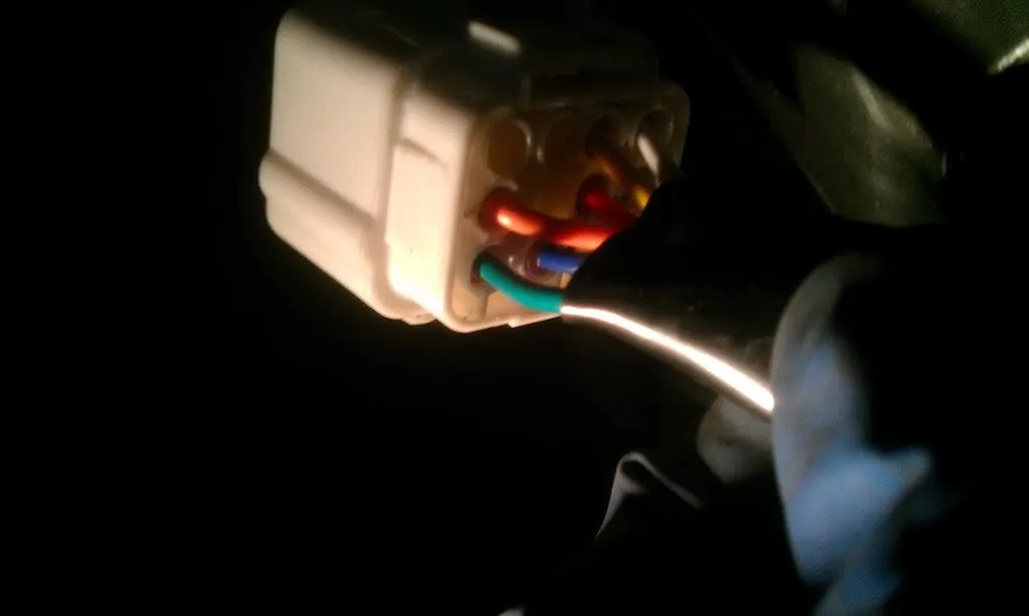
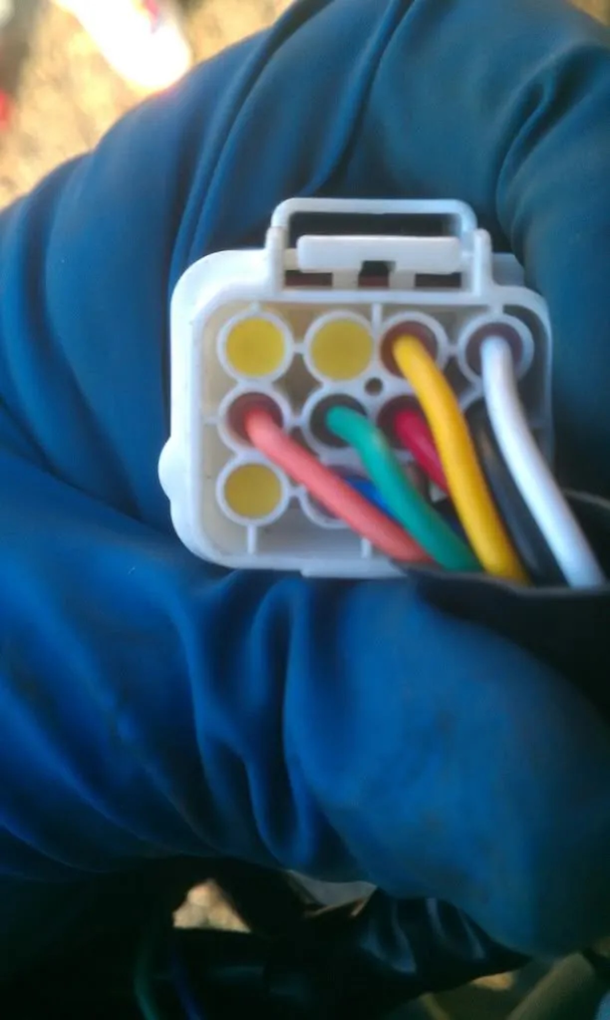
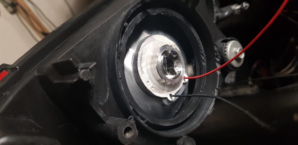
The green wire is the parking light wire, which is located in the bottom left of the connector.
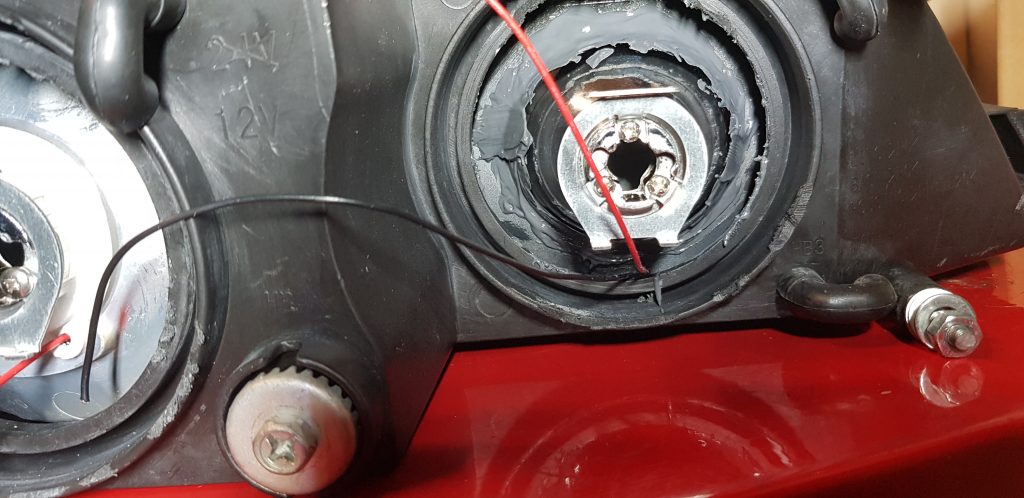
Where my pick is pointing is where the green wire needs to be inserted.
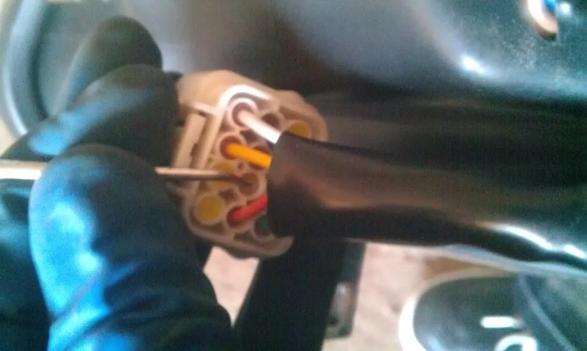
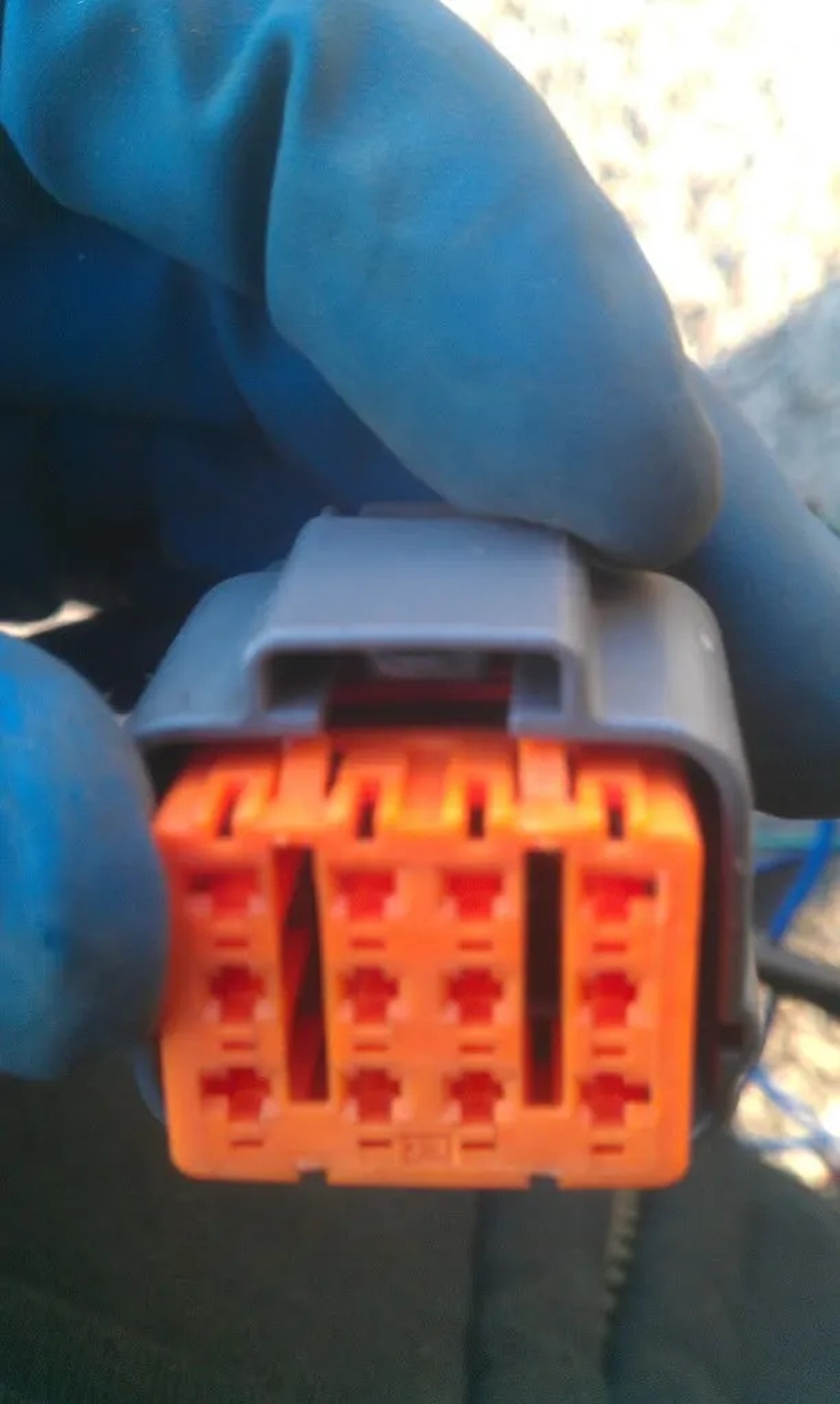
Inside the connector, there’s an orange insert that keeps the pins from being pulled out. If you look at the top of the orange insert, there are two clips that need to be lifted to remove the insert. I used a fine straight pick from Craftsman.
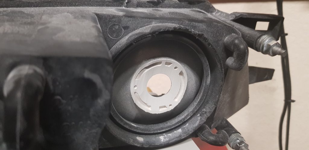
Put the pick under the pin, push down, and pull the green wire out. You also need to remove the rubber grommet where the new pin needs to be inserted. Use the straight pick to push it out. Once you get the pin and the grommet out, insert them into the new location. It should look like this.
And this is your end result. Be sure to put the rubber grommet into the other location to prevent water from getting into the harness and causing corrosion.
In this article, I go over the process for doing quad projector lights retrofit in eBay R34 Maxima headlights. Specifically the 4th generation Maxima(95-99). The projectors used were inexpensive Mini H1 projectors (https://amzn.to/2GX9GaA).
The previous lights I had on the car were FX35 projectors but the job was not great and I wanted to clean up the look of the front end of the car. I bought R34 headlights from eBay and with some modification, they fit well (I made a video and article on that here). I wanted to do an inexpensive retrofit job that was much cleaner than the previous one. I opted for Mini H1 projectors which are the common projectors that have a threaded shaft at the back and allows you to slide them through the cars existing housing light bulb socket hole.
It is common to use an oven to bake the housings to then remove the lens cover. However, I used a heat gun to loosen the glue holding the covers. Being inexpensive units, it was easy to separate them; OEM lights are tougher because they are properly sealed and glued. I separated the cover from the housing and then tested the projector. I first tested it on the low beam side. I slid the projectors threads through the R34’s bulb hole and right away saw an issue. The projectors’ back shaft was not long enough to be able to catch any threads with the nut that holds the projector in place.
Lens cover separatedR34 shroud modificationI used an angle grinderR34 shroud modificationR34 shroud modification
I took out the grinder and started cutting. I used the side edge of a thick grinding wheel to remove some material from the R34’s bulb socket. I then was able to slide through the projector again and catch plenty of threads to put the nut and H1 bulb retainers. The projector looked great, it is said that the vertical alignment is not bad because it is using the stock bulbs hole which is lined up somewhat. But the rotation needs to be addressed, I eyeballed it at first to test putting the lens covers. They looked great, so next was the high beam side.
The high beam side is a different story, there are two issues to address. One, the bulb hole is too small to fit the projector back shaft through. The second is that even if you could slide the projector through, it would sit to far forward and hit the housing lens cover. In comes the angle grinder again, the goal here is to cut an oval so that the projectors reflector can sit on that oval deep into the housing and away from the lens cover; a file was used too. While cutting I would test the projector once in a while and ensure I was cutting a clean enough oval to not have gaps around the mating area to the reflector.
Next was the painting, I decided to go with an all-black housing; glossy. I painted everything except the projectors shroud. First I sprayed it with a primer and then the black. Once dry I went to line up the projectors.
To line up the projectors I mounted the housings on the car with no lens cover and used the garage wall. I know its very close but I felt it was good enough. I put in the bulbs then turned them on and rotated the projectors till I saw a horizontal line on the wall. This was not too hard because the high beam projector stays in place due to the shroud touching the floor and ceiling of the housing; holding it in place. This allowed you to rotate it to match the low beam projector. Once I had that set, I then slowly took them off so the high beam projector would not move. Then I sat it down and applied JB Weld to the back of the high beam projector. I used the original JB Weld.
Once the JB Weld was set on both housings all there is left to do is to put the lens covers. I heated the glue areas with the heat gun all around then I placed the cover on and pressed it with my palm against the housing. I then worked on the electronics, I originally had HID ballast’s with D2S bulbs on the FX35 projectors. I wired in another set of ballasts, h1(hid) bulbs as well as relays. I turned them on and waited about 15 minutes to see how hot the wiring and the housing lens cover got. The front of the lens cover gets pretty hot, it is a focused beam like using a magnifying glass to burn with the sun. The back of the projectors got extremely hot, I was not comfortable at all with it; it felt like it could burn wiring or anything near it. So I then ordered H1 LED’s, removed the ballasts and wired the new bulbs in. The output still looks great with LED’s, you can see more intensity with the HID’s for sure but LED’s do not stay far behind so far.
I am very happy with the results and it was exactly how I pictured it. The front of the car looks aggressive and different. I will give an update with night time shots and some feedback.
**THIS SETUP IS FULLY INDEPENDENT TO A SEPARATE TOGGLE SWITCH, PULLING POWER FROM YOUR AMPS POSITIVE WIRE, IT WILL NOT WORK WITH YOUR SHIFTER**
I only have an HID in the driver’s side. The passenger side is LED which has stock functionality with the shifter. I did this so I wouldn’t have to use the HID every time I back up, every time I shift into Drive causing the ballast to fire up for a split second passing reverse reducing the life span, and to be able to blind tailgaters behind me on the highway. You have no idea how many people get my attention to tell me one of my reverse lights are out. If you decide to do HIDs on both sides then just combine the positives from each ballast and ground negatives on each side near the ballast.
The “Pilot Safety” toggle switch I used had 3 wire connections. If you get a switch with only two connections, then tough titties, you figure out how that shit works, I don’t know, don’t ask me. I used regular speaker wiring (16 or 14 gauge I think, you don’t wanna use anything too small for obvious reasons) and “crimp style” connectors.
Wires will connect from:
SWITCH TO IN-LINE FUSE TO POWER
SWITCH TO GROUND
SWITCH TO BALLAST
BALLAST TO GROUND
(Switch)
Find a suitable place to mount the switch and figure out how to run wires to that location. I put mine where the heated seat switches would be if I had leather, which I don’t. Lucky me because running wires from there was extremely easy, and was an extremely convenient location to hit the switch on the go. I just ran it straight back underneath the center console, through the rear hump on the floor to under the bench seat. Then to the amp/cap and around the “carpet” lining of the trunk.
(1st wire – power input to switch)
I pulled power from my Amp/Capacitor wiring which goes directly into the switch. If you don’t have an amp, just run a wire from the battery. This is where you use appropriate sized “crimp style” connectors. You can also use a distributor block to split the amp wire so one goes to the amp and the other goes to the switch. Me being ghetto and cheap, my power wire is connected directly at the positive connection of the capacitor itself. Before I had the capacitor, I had it connected directly to the amps power/positive connection with no problems.
(^HIGHLY RECOMMENDED: Use an “in-line fuse” here BETWEEN the amp and the switch, so you don’t blow the bulb, ballast or switch, due to any spikes or whatever. I think a 10-15amp fuse will suffice but start low, fuses are cheaper to replace. I have one but I haven’t even put it in yet and haven’t encountered any problems thus far. I’m just connected directly.)
(2nd wire – Ground)
Wire comes out of the switch and is grounded to any suitable bolt. Mine is actually grounded at the amps negative terminal, don’t ask me why, it’s probably wasn’t the brightest idea, but I did. (Haven’t encountered any problems yet) Then run a ground from the negative terminal of the ballast to any suitable bolt. (Good, now your nice and grounded)
(3rd wire – Output Power wire)
Comes out of the switch goes straight to the positive connection to the HID Ballast. (Again, appropriate sized “crimp style” connectors were used here on each ends, but your set up may be different, I don’t know know. I’m not there.)
How you fit the bulb into the tail light is all up to you. I got mine from Gregory Lachhman in New York who did his a long time ago. He got an extra Oem bulb socket from the the JY or whatever, drilled a big enough hole through it to fit the bulb, and sealed it in place with JB weld I think. He helped me through this when I did it so credit goes out to him. So my HID bulb is pretty much plug and play. Perfect fit. Although if the bulb blows out, I’m gonna have to find another socket to drill a hole in and fit the bulb.
I used a slim ballast and just used double sticky tape to mount it to the inner fender wall.
My bulb is 6000k.
I’m sure there are many other methods to doing this, but this is how I did it. If this DIY has helped you, please post a pic of your setup and tag me in it. Thanks.
Before You Start:
The purpose of this modification is to re-wire your fog light relay under your hood to receive signal from an accessory source of power that is independent of anything else in the car, allowing you to turn on your fog lights without the headlights as well as run them with your high beams. The modification is very inexpensive and will avoid/end the problems with the “windshield wiper” write-up.
Steps:
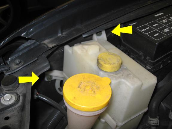
1. First off your going to want to locate the relay box located on the left side of your under hood as indicated by the arrow.
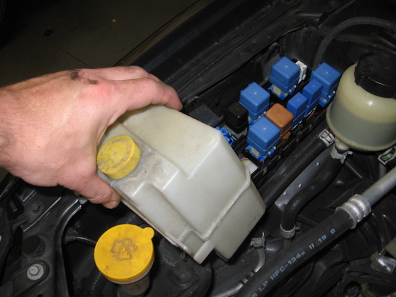
2. Then you will want to remove the reservoir in between you and the relay panel. This is attached by two 10mm bolts on the left side of the car. Following this, set the reservoir aside.
3. Next you will want to remove the cover from the relay box prying the two tabs holding it on outward and lift the cover up.
4. Now you will want to remove the air conditioning relay and the heated mirror relay if you are equipped with them. To do this, use your pry tool and insert on the side of the relay that has a clip, push away from the relay and then pull up on the relay itself.
5. Next remove the two exposed 10mm bolts holding the relay box in. Now pull up on the box and release the snap tab located on the bottom arm of the box.
6. Once the relay panel is free from the car you will need to open it to expose the wiring inside. To do this release the 3 clips on the right and left side of the box indicated with the arrows. Then open.
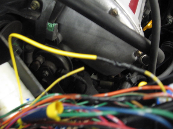
7. Now that you have the wiring exposed you are going to be working with the signal wire from the fog relay and the accessory power wire from the air conditioning relay. The yellow wire coming out of the fog relay is the wire you want to give +12V and the pink wire with a blue stripe from the A/C relay is where you will get it. To access the pink wire better you will probably need to remove the relay harness from the housing. To do this pry in the direction indicated and push out the bottom of the housing.
8. Now cut the yellow wire and without cutting the pink wire run a wire from it to the yellow wire leading into the blue relay harness.
9. I prefer soldering all of my connections but you can attach how you like. I highly recommend no matter what you do though, make sure to tape up everywhere you work. Make sure to tape up the open end of the yellow wire as well.
10. Now close everything up and reverse the previous steps to return everything how you found it. Flip your fog lights on and admire. You can turn them on whenever you want granted the car is on.
With the 6000k HIDs you wont really be able to see the halo rings. the lenses that they use give off a slight glare which actually make the HIDs look a little brighter than they are, which to me isnt a bad thing at all. i would post a pic of them lit on my car but its in the shop.
One of my buddies here in MI bought the ebay projector head lights and his bulbs weren’t seating properly. The right bulb was bouncing in the housing. They didn’t fit properly and just were cheap quality. So I personally wouldn’t recommend them.
Are people trolling by trying to buy ebay headlights? Only thing they’re good for are the lens lol
Ebay halo’s suck… ZERO light distribution. Youd have more light on the road getting 5th gen headlights and silverstars lol.


")


")


")


