Tag

troubleshooting

Browsing

Community Member Credit: Eddy

I started having issues with my rear trunk latch life gate on my 2004 Infiniti FX35. It just wouldn’t open. For some time, I was just removing the trunk 15A fuse where it would reset the latch. It would eventually open. But this ultimately got worse. I got tired of taking the fuse in and out whenever I wanted to open the trunk. Also, I really didn’t want to spend $100+ bucks on the part to fix it, so I figured I’d try whatever was out there.

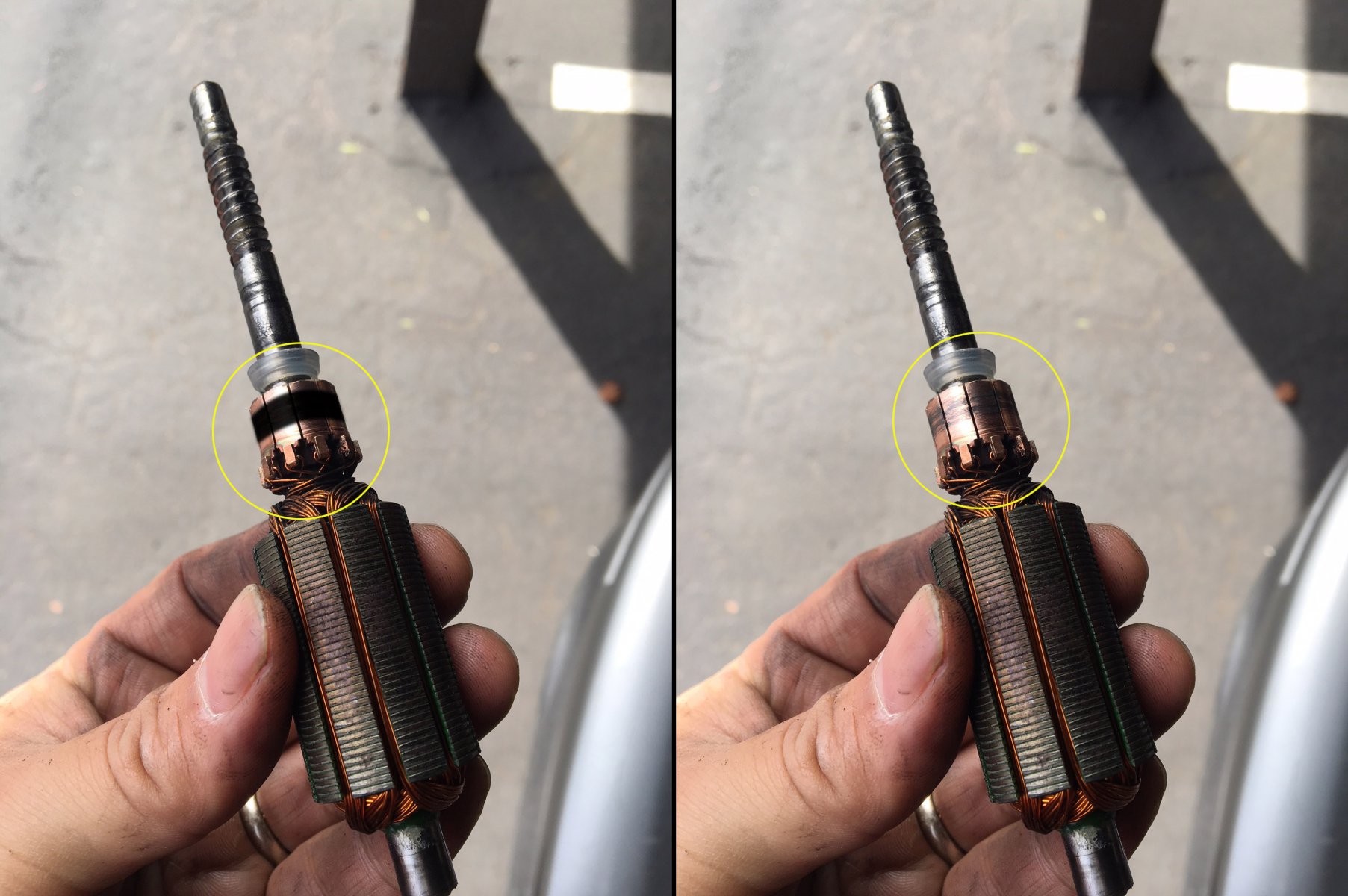
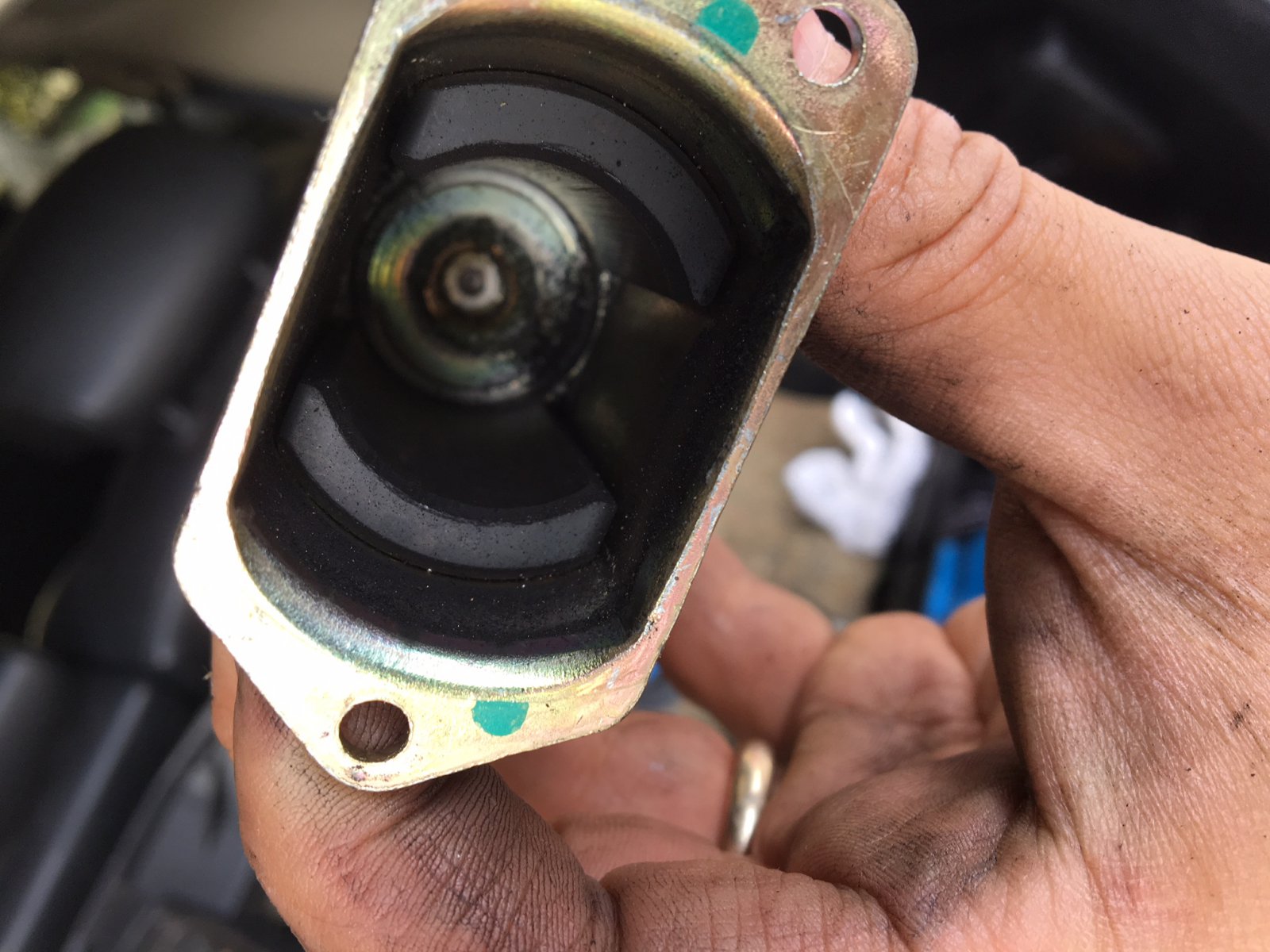
So I tried the solution in this write-up. I won’t take all the credit because I found some info on one of the FX35 forums (member Jim Lee). It took me about 20-30 minutes to do and WOW, everything works again. It’s been a few days now and all works fine. Basically, you turn your motor back to brand new again by following this how-to. The motor has something called a ‘commutator’. It needs to be super clean. When I took my motor out, it was very dirty and black. It is the common issue of the brushed motor. You can Google “Commutator” to learn more about it. 

Update 4/9/2021: This officially resolved my issue. All is good and saved me a bunch of $$$. 

Commutator Reference Photo:

Summary: I would recommend try this how-to. It will save you a lot of money and it’s very simple to do. The part is about $100 bucks and labor may be another $100 bucks. This was FREE to me and just took 20 minutes of my time. Plus you learn a little about how these things work.

Nissan OEM Part Replacement Information

If you are looking to just replace and not attempt this how-to, below is the information you need to order the correct part for your FX35. Please cross-check the part number to ensure it works for your generation FX35.

Part Description: Motor-Closure, Back Door
Part Number: 90554-AQ000
Price: $124.03

This video below will show you how to remove the plastic covers to expose and take out the latch motor.

How to Fix and Clean Motor “Commutator”:

Original Photo Credit: Jim Lee via FX Forums

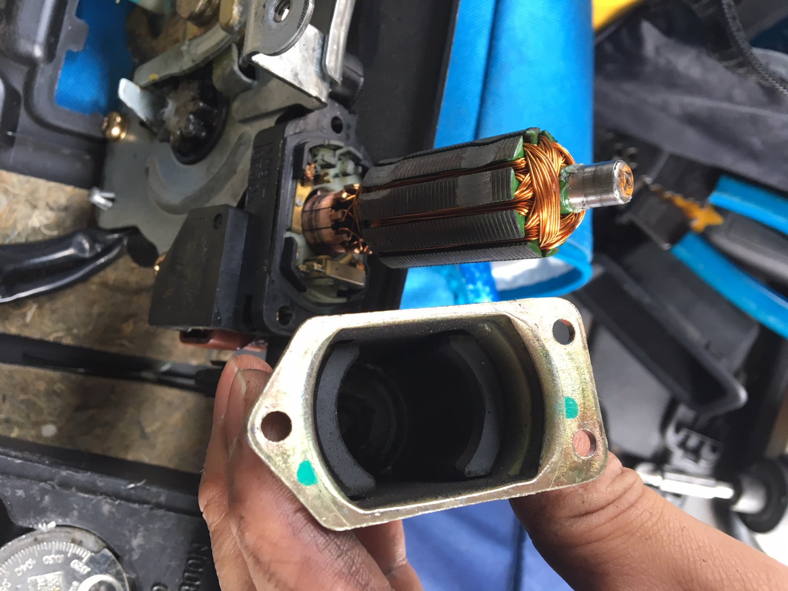
After doing the above and taking out the motor, you can follow the steps below:

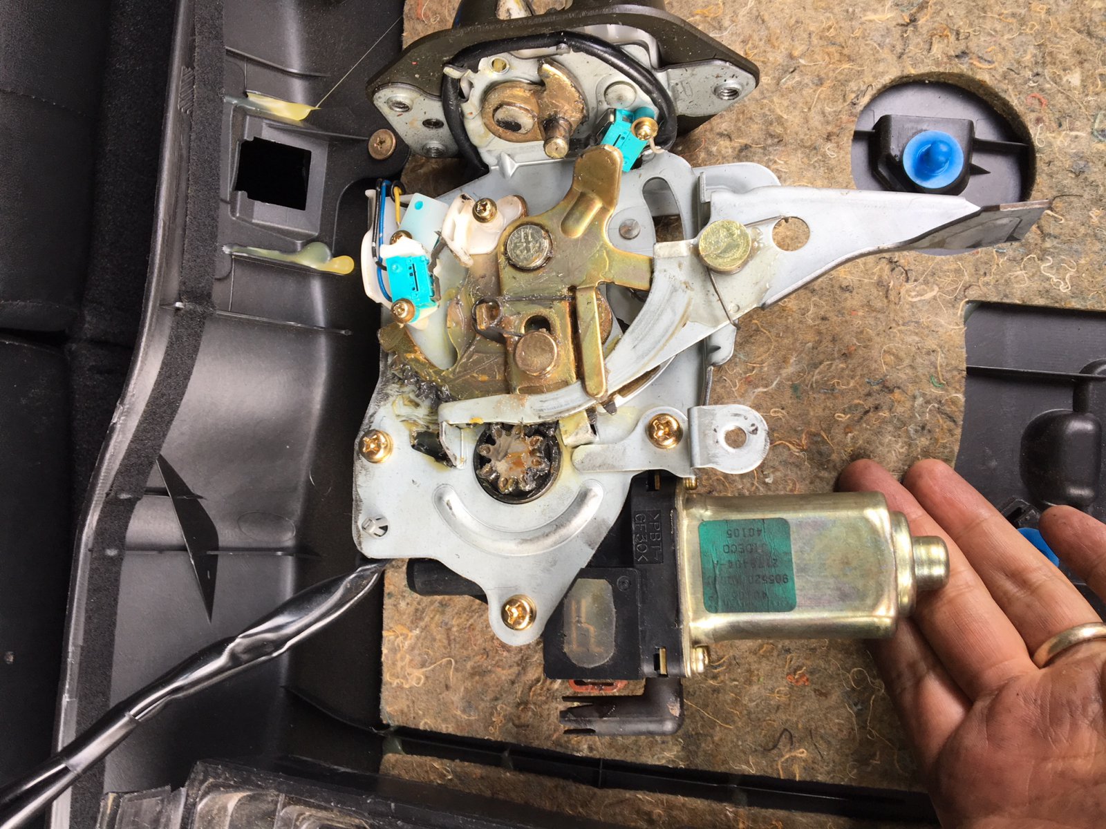
Take off the 3 screws on the motor.

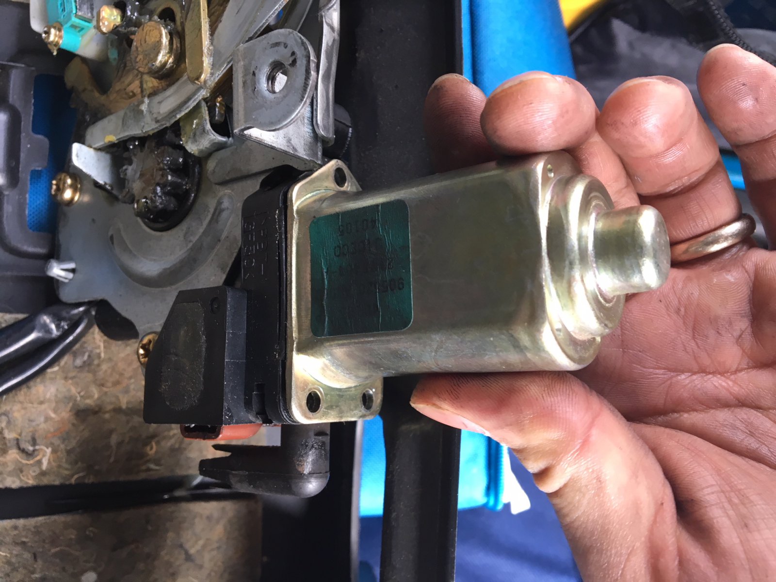
Pull the shaft out of the housing.

Simply use a terry cloth rag and apply some elbow grease back and forth to clean it.

These were actual pictures of my FX35. You can see how dirty it was as seen above. You can see the green cloth I used.

After cleaning it, it looks like this. Literally brand new again!

Put everything back together. AND NOW EVERYTHING WORKS AGAIN! Before I would have to take out the trunk fuse in order to reset it and hoped it opened. Now it opens consistently with no issues at!!

Motor Reference Photos:

Loading

Credit: Travis Barker

Issue:

  • Got a few codes the other day that put the car into limp mode P0643 P2122 P2138. Thought the issue was the Pedal position Sensor until I replaced it and cleared the codes so I could start the relearn process, but the p0643 code didn’t go away. I Tested the Sensor Power supply but the voltage was about 3.88V from both the pedal position sensor end of the harness and the terminal circled in the photo coming straight out of the ECM I tested the other pedal position sensor power supply and it was showing 5.02V.

Diagnostics:

  • Update had my ECM sent out to be tested and repaired, was told they weren’t able to find any issues with the output voltage but there was something inside which was “unrepairable” that didn’t look right so they asked if I wanted to buy a new pre programed ECM and of course I said yea sure, about 2 weeks later the ECM came put it in still had the P0643.
  • Checked all my grounds and noticed one was loose but the head of the screw thats holding it is facing the other way inside of the dashboard, so the only way to adjust it is to remove the dashboard and tighten it. So I took apart the dash and moved it slightly enough to just reach and tighten the ground screw, turned the car on boom p0643 still there.
  • Went back into the FSM and started to wonder about the 2 sensors I didn’t check the voltage on which was the power steering pressure sensor and the EVAP pressure sensor. Jacked up the rear and checked the EVAP pressure sensor for water in the connector and the power supply voltage, it was about 2.88 volts.
  • Then decided to check the power steering pressure switch, The connector looked fine but the tubing around the harness felt hard like heat got real close to it. I put my hand up farther to feel the rest of the harness and found the issue, the harness for the power steering sensor melted and joined together.

Solution:

  • Once I cut off the burnt end on power steering switch, separated the wires and cleared the code everything works as it should! So for anyone with the p0643 issue be sure to check all the sensors and the harness showed in the FSM!

Photo of Power Steering Switch Plug:

Loading

Credit: Nopike

The information display on my 2014 recently stopped working I suspected a bad connection. I removed the gauge cluster and found the ribbon connector, located at the rear of the cluster, This ribbon connects the small LCD display to the cluster.

Because it is pretty cheap and flimsy this connector can come loose and cause the display to not work at all or not work properly. I just removed the plastic connector and reseated it and the ribbon cable. The display now works fine. I’m willing to bet this is the cause of the majority of the problems with this display. Removing the cluster is a surprisingly easy job. I think most people could do this repair in 30-60 minutes.

I would not be surprised if other Nissan vehicles such as the Altima have the same issue. The instructions, although relatively simple, make it look more complicated then it really is. If you work slowly and carefully there really is not much you can screw up. I think I had to remove a total of 5 or 6 screws to get the display out You may have to remove a couple of connectors.

Instructions (Credit: walters_12)

Well, we finally got some near-freezing temps on a sunny day that allowed me to be outside for a while. Nopike was correct on two fronts: the fix worked and the entire job took about 30 minutes. So, an absolutely huge thanks; you saved me at least $1,000! I should mention that, much to my disappointment, this fix did not work immediately; however, my Information Display came back online after about 30 minutes of driving. It could have something to do with how I placed the Information Display’s ribbon cable (see below). Admittedly, I was a bit nervous before starting, but I think most anyone can tackle this job. As a reference, I’m handy, but have no experience with anything auto-related. Pictures are posted in the next post (the first and last pictures were taken just over a month apart). Below is a description of the steps I followed to complete the job.

Documents

1) I downloaded the 2012 version of section IP-Instrument Panel and printed pages IP-10, IP-11, and IP-16.

2) I also downloaded the 2014 version of section MWI – Meter, Warning Lamp & Indicator as the 2012 version did not exist) and printed page MWI-122.

Tools:

  1. Standard (flathead) screwdriver
  2. Philips screwdriver (8” or longer)
  3. Needle-nose pliers
  4. Hand towel or t-shirt

Steps:

*Note parentheses indicate the part number on page IP-10, whereas the brackets indicate the document page numbers.

  1. Move the steering wheel to middle-lower position. I didn’t, but it would have made getting at the Combination Meter screws easier.
  2. Disconnect the battery
  3. Remove the Instrument Side Finisher (5) [IP-16]. It pops off with standard screwdriver and gentle pressure.
  4. Remove the Fuse Block Cover (8) [IP-16]. It just pulls off.
  5. Remove the Instrument Lower Panel (7) [IP-16]. There is one screw you’ll see after removing Fuse Block Cover. There are also three metal clips near top (two left; one right) that pop off with a gentle pull. I let the Instrument Lower Panel hang gently, but you could (optionally) completely remove the Instrument Lower Panel by disconnecting the harness connectors and aspirator hose.
  6. Remove Cluster Lid A (22) [IP-16]. There are two screws near the bottom and four metal clips evenly spaced at top that pop off with a gentle pull. I just let it hang over the center console.
  7. Place a towel or t-shirt on top of the steering column to prevent scratches and remove the Combination Meter (15) [MWI-122]. There are three screws (bottom left, bottom right, top middle). I completely removed the Combination Meter by disconnecting both wire harnesses. I did the rest of the job inside the house.
  8. On the back of the Combination Meter, identify gold ribbon cable for Information Center (bottom, middle). Using a needle-nose pliers, I removed the long, tan plastic piece holding ribbon cable. I then placed the ribbon cable back into position (there will be leeway left and right) and reinstalled the long, tan plastic piece that holds the ribbon cable.
  9. Reassemble by following steps 1-7 in backwards order.

Loading

Community  Member Credit: prostreetonline

reader

The DTC ODBII trouble code P0335 on a VQ35, found in a Nissan 350Z, Infiniti G35, and many others is a Crank Position Sensor fault, or CKP for short. For this particular write-up we will be showing you How to Service a VQ35 Crank Position Sensor in a Infiniti G35. This sensor is a hall effect-magnetic style sensor that picks up the high and low parts of the flywheel to determine what position the crank is in.

The differences in the teeth of the flywheel provide changes in the voltage feedback given to the PCM from the crank position sensor. The P0335 DTC can be triggered by a few conditions in your VQ35, and needless to say your car will not operate correctly or even start with this DTC.

Here are the detecting condition of the DTC P0335 error code.

Where is my Crank Position sensor?

Easily the most commonly asked question in our How to Service a VQ35 Crank Position Sensor guide. The VQ35 has it’s Crank Position Sensor ( CKP ) located on the bellhousing of the transmission, and it reads the position of the crank by reading the teeth on the flywheel.

how-to-test-vq35-ckp2

How do I know my crank position sensor is bad?

To test your crank position sensor, first raise the vehicle and locate the crank position sensor and the plug leading to it.

ckptest


Now that you have located the sensor, unplug the sensor and take a look at the 3 prong weatherproof connector. Don’t forget if you need the how to on servicing your camshaft position sensor, we’ve got you covered.

First you should check the continuity of the wiring by placing the negative terminal on a ground, and then putting the lead to pin 3.

how-to-test-vq35-ckp

Continuity should exist here, so move on to the next step of our How to Service a VQ35 Crank Position Sensor writeup.


ckptest1


You can test this sensor using a voltmeter with one end connected to a chassis ground and the positive lead going to the 1 pin on the weatherproof connector.

If these 2 wires have continuity your part is more than likely damaged, as the 2nd pin is the signal wire to the PCM.

volt1


Why does my car not start?

The crankshaft position sensor is not transmitting any information to the PCM when trying to crank over your motor, without this sensor the PCM will not know how to operate the engine. This is when you will absolutely need our How to Service a VQ35 Crank Position Sensor article to get your car back on the road.

Where is the Crank Position Sensor pin on my VQ ECU?

Pin 13 is the Crankshaft Position Sensor on your VQ PCM, here is a diagram to help you test continuity should you need it.

vqecupinout


This magnetic crank position sensor can be tested by measuring the resistance between terminal 1-2, terminal 1-3, and terminal 2 and 3.

ckptest3


All 3 of these combinations must measure resistance at 0 Ω or ∞, if your measurements are outside of this reading your sensor must be replaced.

Once you have the unit replaced, plug in your favorite ODDII scanner and clear the code P0335 and you are ready to rock and roll!

how-to-test-vq35-ckp1

You have now serviced your VQ35 crank position sensor and saved yourself a lot of money in dealer labor.

Happy Driving!

Loading

Credit: 2000_Maxima_SE

Symptoms:

  • Today I replaced the fuel pressure regulator. Still no change. I’m still having trouble starting the car. I would have to step on the gas pedal a few times, not all the way though before it’ll start.

How to troubleshoot:

  • This requires two people and one if you have remote start. Disconnect the Vacuum line of the Fuel Pressure Regulator AND Fuel Pressure Damper and check for fuel. There should be NO fuel present in the Vacuum lines or Vacuum port of the Fuel Pressure Regulator and Fuel Pressure Damper.
  • Total Diagnostic time: 5-10 minutes.
  • Difficulty: EASY

The solution:

  • A New O.E. Fuel Pressure Regulator ($70-$120 on EBAY)
  • A New O.E. Fuel Pressure Damper ($115-$150 on EBAY)

** Anyone with basic mechanical skills should be able to replace these parts in 2-4 hours. It’s VERY IMPORTANT when dealing anything fuel related on the car to relieve all the fuel pressure out by removing the 15 AMP Fuel Pump fuse in the fuse box under the dash of the driver side, removing the fuel cap, and starting the car until it can’t start anymore. **

Tools needed for this job:

  • 10mm socket with ratchet
  • Socket extension
  • Flathead screwdriver
  • Pliers

The Fuel Pressure Regulator and Damper is fairly easy to replace.

  1. Remove Air Intake.
  2. For the Fuel Pressure Regulator, remove the two 10mm bolts on it. Use pliers to move the clamp down on fuel hose. Then CAREFULLY use a flathead screwdriver to pry off the the fuel hose and vacuum hose on the Fuel Pressure Regulator.
  3. For the Fuel Pressure Damper, there are a total of 5 10mm bolts you have to remove. Two on the Damper, one on the bracket in the middle of the damper hose, and two at the end of the damper hose. Use pliers to move the clamp down on fuel hose. Then CAREFULLY use a flathead screwdriver to pry off the the fuel hose and vacuum hose on the Fuel Pressure

**Make sure there is an O-Ring on the Fuel Pressure Regulator and Damper or else Fuel will be everywhere when you attempt to start the car**

I hope this thread is helpful to anyone who is having similar problems on their Maximas. GODSPEED

Loading

Credit: 5thgenmaxima/puppetMaster

Your MAF is located on your air box between your Throttle body and Air filter. It sets about 8-12 inches back from the air filter itself. It has 2 Torx screws holding it down.

The 4 wires are color coated as follows (2000 model) from right to left. (From passenger side to driver side) (Left to right in the pictures)

  • White Wire: Signal wire – This will change as your speed/load changes – This is the wire the ECU/TCM takes information from to alter shifts, A/F ratio, timing,etc.
  • Red Wire: Reference wire – This should stay the same. This wire is from a hot source and has some sort of resistor to send only 5 V to the wire.
  • Black Wire: Ground wire – Should be .05 or less VD from battery ground.
  • Red Wire w/ Green Strip: power wire – Should be battery voltage.

Thanks to puppetMaster for the MAF signal specs they are as follows. All readings are at Engine operating temp, and no load. ( radio, head lights, ac, heat off).

  • SIGNAL WIRE (White Wire)
    Idle: 1.1V-1.5V  (Alldata says 1.2 – 1.8 volt)
    2500 RPM: 1.7V – 2.4V
  • Reference Wire (Red Wire): should be @ or just below 5 V. If this is low your MAF signal wire will send low #’s to the ECU.
  • GROUND WIRE (Black Wire): .05V or less – Should not change more than .02 volts with load or engine speed increase.
  • POWER WIRE (Red with Green Strip) Battery voltage. (13 – 15V) Should be close to the voltage you get when checking battery terminal to terminal. Alldata says 11-14.
    IMO- If you have 11V your battery is either dead or you have an electrical problem….. again-IMO.

I couldn’t find any specs for the ground or reference so these are universal specs among all domestic/import MAF sensors.

Loading

Community Member Credit: 96SEmaxB

So I started blowing this in cab 10amp fuse called meter, I checked alternator, battery, called harness lights all the normal stuff, couldn’t find it, meanwhile that fuse controls the cluster and puts the vehicle into fail-safe mode… so I scoured the forums and google and was running out of free time and fuses, so I brought it into the shop (local mechanic)…

It took him 9 hours of following wire and circuit diagrams, Forums, calling Nissan dealerships, had everything unplugged from harness and couldn’t find what was causing the short…

He then noticed on the schematics for that circuit there was a mirror section, not side mirrors but rear mirror, apparently the connection at the actual rear view mirror was toast, melted the wires and shorted internally, unplugged mirror and voilaaa fuse didn’t blow.

So 870$ later I had the issue fixed, a measly 100$ mirror crippled my baby for 3 days and cost me 900$.

I’m just posting this so anyone that runs into the same issue to remember that the rearview mirror may not b on the diagram plainly, but it’s something to check also.

Additional Note:

THANK YOU SOO MUCH

  • This problem happens for me a while back and replaced the fuse and it didn’t pop it happened again and I spent the whole day looking for a short and YouTube videos and forums and I found this one went and looked at the wires behind the mirror they were barley touching so I pulled them apart and replaced the fuse again and it didn’t pop so thank you soon much for your forum.

Loading

Community Member Credit: Greg Allen

For future problem solvers, my 2003 Maxima brake and battery lights were flickering. The lights were eventually solid with no battery charge leading to believe an alternator problem. Went through the process of replacing the alternator with a remanufactured unit from Advance Auto. I got everything back together and the battery still wasn’t charging.

I realized the Alternator ground bracket was corroded as can be. Being my first time diagnosing my electrical system I’m now understanding the need for all clean & tight connections. I ended up getting out the multimeter to test continuity and it was so corroded in many spots there was none. I cleaned connections with a silver wire brush on drill brought it from 4v to 14.5v on the new alternator.

Loading

Community Member Credit: Thrillho

In case you’ve disrupted your throttle body and need to perform the Idle Air Volume Relearn, you’ve probably noticed that it doesn’t “stick” , meaning it worked fine for the time being and then it didn’t.

I am using the Nissan Data Scan app with an ELM obdii Bluetooth adapter, the car’s 2000 Maxima GLE.

In order to make the Idle Air Volume Relearn stick using any of those apps and Bluetooth adapters, you can’t wipe any pending codes before/after Relearn is performed; for some reason when you use a third party app instead of Nissan Consult, it’ll write the changes onto the same partition as the error codes. What that means is you’re gonna write the IAVR over any pending existing codes in order to make it stay.

1. Don’t wipe any codes or clear the SES light
2. Perform idle air volume relearn

It’ll stay on your ECU as long as there is a pending code or the SES light is on. Once you clear the code and the SES light, your idle air relearn goes away as well. If you clear your codes and then do the relearn, your relearn will get overwritten once the code comes back. If you do the relearn with a pending code, it’ll stay there along with the code.

Loading